Sign In
Upload
Download
Table of Contents
Contents
Add to my manuals
Delete from my manuals
Share
URL of this page:
HTML Link:
Bookmark this page
Add
Manual will be automatically added to "My Manuals"
Print this page
×
Bookmark added
×
Added to my manuals
Manuals
Brands
Hirschmann Manuals
Network Router
RSB20-0800T1T1
User manual
Hirschmann RSB20-0800T1T1 User Manual
Installation industrial ethernet rail switch basic, rsb20 family
Hide thumbs
1
2
Table Of Contents
3
4
5
6
7
8
9
10
11
12
13
14
15
16
17
18
19
20
21
22
23
24
25
26
27
28
29
30
31
32
33
34
35
36
page
of
36
Go
/
36
Contents
Table of Contents
Bookmarks
Table of Contents
Table of Contents
Safety Instructions
About this Manual
Key
1 Device Description
Description of the Device Variants
Device Variants with 8 TP Ports
Device Variants with 6 TP Ports and 2 FX Ports
Device Variants with 6 TP Ports and 3 SFP Slots
Device Variants with 8 TP Ports and 1 FX Port
Device Variants with 6 TP Ports and 3 FX Ports
2 Assembly and Start-Up
Installing the Device
Unpacking and Checking
Installing the SFP Modules (Optional)
Insert Data in Label Area
Connecting the Terminal Blocks for Supply Voltage and Signal Contact
Installing the Device on the DIN Rail, Grounding
Dimension Drawings
Installing the Terminal Block, Start-Up Procedure
Connecting the Data Lines
Display Elements
Basic Set-Up
Disassembly
3 Technical Data
A Further Support
Advertisement
Quick Links
1
Table of Contents
2
Device Variants with 6 Tp Ports and 2 Fx Ports
3
Device Variants with 8 Tp Ports
4
Device Variants with 6 Tp Ports and 3 Sfp Slots
5
Installing the Device
6
Display Elements
7
Basic Set-Up
8
Technical Data
Download this manual
User Manual
Installation
Industrial ETHERNET Rail Switch Basic
RSB20 Family
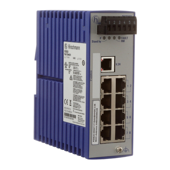
RSB20-0800T1T1
RSB20-0900ZZZ6
RSB20
Release 20 09/11
RSB20-0800M2M2
RSB20-0900M2TT RSB20-0900MMM2
Technical Support
HAC.Support@Belden.com
Table of
Contents
Previous
Page
Next
Page
1
2
3
4
5
Advertisement
Table of Contents
Need help?
Do you have a question about the RSB20-0800T1T1 and is the answer not in the manual?
Ask a question
Questions and answers
Related Manuals for Hirschmann RSB20-0800T1T1
Network Router Hirschmann rsb20 Reference Manual
Web-based interface industrial ethernet switch (142 pages)
Network Router Hirschmann RS20 User Manual
Industrial ethernet switch (78 pages)
Network Router Hirschmann RSB20-0800M2M2 User Manual
Installation industrial ethernet rail switch basic, rsb20 family (36 pages)
Network Router Hirschmann RS20 Reference Manual
Gui graphical user interface industrial ethernet (gigabit) switch (254 pages)
Network Router Hirschmann RS40 User Manual
Industrial ethernet (gigabit) switch (78 pages)
Network Router Hirschmann RS20 User Manual
Industrial ethernet (gigabit-)switch with software l2e, l2p, l3e or l3p (60 pages)
Network Router Hirschmann RS20 Programming Manual
Industrial ethernet (gigabit) switch (116 pages)
Network Router Hirschmann RS20 Reference Manual
Industrial, gigabit (228 pages)
Network Router Hirschmann RS20 Series User Manual
(34 pages)
Network Router Hirschmann RS20 User Manual
(228 pages)
Network Router Hirschmann RS20 User Manual
(220 pages)
Network Router Hirschmann RS20 Reference Manual
Command line interface industrial ethernet gigabit switch (396 pages)
Network Router Hirschmann RS2-FX-LH/FX-LH Description And Operating Instructions
Industrial ethernet rail switch 2 family (10 pages)
Network Router Hirschmann RS2-FX-SM/FX-SM Description And Operating Instructions
Industrial ethernet rail switch 2 family (10 pages)
Network Router Hirschmann RS2-5TX/FX Description And Operating Instructions
Industrial ethernet rail switch (6 pages)
Network Router Hirschmann RS30-...U Series User Manual
Industrial ethernet rail switch (44 pages)
This manual is also suitable for:
Rsb20-0900zzz6
Rsb20-0800m2m2
Rsb20-0900mmm2
Rsb20-0900m2tt
Table of Contents
Print
Rename the bookmark
Delete bookmark?
Delete from my manuals?
Login
Sign In
OR
Sign in with Facebook
Sign in with Google
Upload manual
Upload from disk
Upload from URL


Need help?
Do you have a question about the RSB20-0800T1T1 and is the answer not in the manual?
Questions and answers