
Related Manuals for National Instruments IMAQ PCI-1409


Summary of Contents for National Instruments IMAQ PCI-1409
- Page 1 IMAQ ™ ™ IMAQ PCI/PXI -1409 User Manual High-Quality Monochrome Image Acquisition Boards for PCI, PXI, and CompactPCI Bus IMAQ PCI/PXI-1409 User Manual November 2000 Edition Part Number 322811A-01...
- Page 2 Switzerland 056 200 51 51, Taiwan 02 2377 1200, United Kingdom 01635 523545 For further support information, see the Technical Support Resources appendix. To comment on the documentation, send e-mail to techpubs@ni.com © Copyright 2000 National Instruments Corporation. All rights reserved.
- Page 3 Warranty The IMAQ PCI-1409 and PXI-1409 are warranted against defects in materials and workmanship for a period of one year from the date of shipment, as evidenced by receipts or other documentation. National Instruments will, at its option, repair or replace equipment that proves to be defective during the warranty period.
- Page 4 Classification requirements are the same for the Federal Communications Commission (FCC) and the Canadian Department of Communications (DOC). Changes or modifications not expressly approved by National Instruments could void the user’s authority to operate the equipment under the FCC Rules.
- Page 5 • Connect the equipment into an outlet on a circuit different from that to which the receiver is connected. • Consult the dealer or an experienced radio/TV technician for help. Canadian Department of Communications This Class B digital apparatus meets all requirements of the Canadian Interference-Causing Equipment Regulations. Cet appareil numérique de la classe B respecte toutes les exigences du Règlement sur le matériel brouilleur du Canada.
- Page 6 Conventions The following conventions are used in this manual: ♦ The ♦ symbol indicates that the following text applies only to a specific product, a specific operating system, or a specific software version. This icon denotes a note, which alerts you to important information. This icon denotes a warning, which advises you of precautions to take to avoid being electrically shocked.
-
Page 7: Table Of Contents
Chapter 1 Introduction About Your 1409 Device ....................1-1 Using PXI with CompactPCI..................1-2 Software Programming Choices ..................1-3 NI-IMAQ Driver Software ................1-4 National Instruments IMAQ Vision ..............1-5 IMAQ Vision Builder..................1-5 Integration with DAQ..................1-6 Vision and Motion...................1-6 Chapter 2 Configuration and Installation What You Need to Get Started ..................2-1 Optional Equipment .......................2-2... - Page 8 Contents Analog Front End Considerations ................. 3-5 10-bit/8-bit Mode .................... 3-5 Chapter 4 Signal Connections BNC Connector ......................4-1 I/O Connector ........................ 4-1 I/O Connector Signal Connection Descriptions..........4-3 Appendix A Specifications Appendix B Custom Cables Appendix C Technical Support Resources Glossary Index Figures...
- Page 9 Contents Tables Table 1-1. Pins Used by the PXI-1409 Device............1-2 Table 4-1. I/O Connector Signals ................4-3 © National Instruments Corporation IMAQ PCI/PXI-1409 User Manual...
-
Page 10: About Your 1409 Device
The 1409 device uses its Real-Time System Integration (RTSI) bus to solve this problem. The RTSI bus consists of the National Instruments RTSI bus © National Instruments Corporation IMAQ PCI/PXI-1409 User Manual... -
Page 11: Using Pxi With Compactpci
Introduction interface and ribbon cable to route additional timing and trigger signals between the 1409 device and up to four National Instruments DAQ, Motion Control, or other IMAQ boards in your computer. Detailed specifications of the PCI-1409 and PXI-1409 are in Appendix A, Specifications. -
Page 12: Software Programming Choices
Using NI-IMAQ, the National Instruments image acquisition driver software, you can program your IMAQ board to acquire and save images. You can use NI-IMAQ with other National Instruments software for a complete image acquisition and analysis solution, as shown in Figure 1-1. -
Page 13: Ni-Imaq Driver Software
Chapter 1 Introduction NI-IMAQ Driver Software The NI-IMAQ driver software is included with your IMAQ device. NI-IMAQ has an extensive library of functions that you can call from your application programming environment. These functions include routines for video configuration, image acquisition (continuous and single-shot), memory buffer allocation, trigger control, and board configuration, as shown in Figure 1-2. -
Page 14: National Instruments Imaq Vision
Chapter 1 Introduction National Instruments IMAQ Vision IMAQ Vision is an image acquisition, processing, and analysis library of more than 200 functions for grayscale, color, and binary image display, image processing, pattern matching, shape matching, blob analysis, gauging, and measurement. -
Page 15: Integration With Daq
Chapter 1 Introduction Integration with DAQ Any platform that supports NI-IMAQ also supports NI-DAQ and a variety of National Instruments DAQ boards, allowing your IMAQ device and NI-IMAQ development to integrate with National Instruments DAQ products. Vision and Motion With National Instruments IMAQ hardware and IMAQ Vision pattern... -
Page 16: Configuration And Installation
LabVIEW – Measurement Studio (LabWindows/CVI, Tools for Visual Basic) ❑ IMAQ BNC-1 shielded, 75 Ω BNC cable for VIDEO0 (included with the 1409 device) ❑ BNC-to-RCA adapter (included with your 1409 device) © National Instruments Corporation IMAQ PCI/PXI-1409 User Manual... -
Page 17: Optional Equipment
A video camera or other video source Note The IMAQ PCI-1409 and PXI-1409 devices rely on your computer’s PCI interface chipset for the highest throughput to system memory. For the best results, your computer should have a Pentium or better processor and an Intel 430 or 440 series or compatible PCI interface chipset. -
Page 18: Figure 2-1. How To Set Up Your Imaq System
NI-IMAQ functions. If you are using IMAQ Vision for LabWindows/CVI, read the documentation for IMAQ Vision for LabWindows/CVI. Figure 2-1. How to Set up Your IMAQ System © National Instruments Corporation IMAQ PCI/PXI-1409 User Manual... -
Page 19: Unpacking
• Remove the board from the package and inspect the board for loose components or any other signs of damage. Notify National Instruments if the board appears damaged in any way. Do not install a damaged board in your computer. -
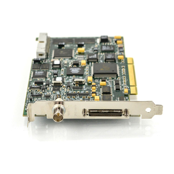
Page 20: Figure 2-2. Pci-1409 Parts Locator Diagram
Figure 2-2 shows the locations of user-configurable jumpers and switches as well as factory-default settings on the PCI-1409. 1 68-pin VHDCI 2 BNC Connector 3 W1 4 RTSI Bus Connector Connector Figure 2-2. PCI-1409 Parts Locator Diagram © National Instruments Corporation IMAQ PCI/PXI-1409 User Manual... -
Page 21: Video0 Input Mode
Chapter 2 Configuration and Installation VIDEO0 Input Mode VIDEO0 has two different input sources via a BNC connector or a 68-pin VHDCI port and two different input modes—referenced single-ended (RSE) and differential (DIFF) input. When you use the BNC input for VIDEO0, set the input mode to RSE (W1 populated). -
Page 22: Installation
Using slow, evenly distributed pressure, press the PCI-1409 straight down until it seats in the expansion slot. Reinstall the bracket-retaining screw to secure the PCI-1409 to the back panel rail. 10. Check the installation. 11. Replace the computer cover. © National Instruments Corporation IMAQ PCI/PXI-1409 User Manual... - Page 23 Chapter 2 Configuration and Installation Your PCI-1409 is now installed. ♦ PXI-1409 You can install a PXI-1409 in any available 5 V peripheral slot in your PXI or CompactPCI chassis. The PXI-1409 has connections to several reserved lines on the CompactPCI J2 Note connector.
-
Page 24: Hardware Overview
The 16 MB of SDRAM also allows you to acquire entire images into on-board memory when necessary. The 1409 device includes four external triggers, four camera control signals, seven RTSI bus triggers, and six video synchronization signals. © National Instruments Corporation IMAQ PCI/PXI-1409 User Manual... -
Page 25: Video Mux
Chapter 3 Hardware Overview The block diagram in Figure 3-1 illustrates the key functional units of the PCI/PXI-1409. RTSI Bus 4 Camera Control Lines Digital 4 External Triggers Input/Output External Clock Generation Circuitry External PCLK, Aspect Ratio Correction HSYNC, VSYNC Acquisition and Genlock Circuit HSYNC, VSYNC... -
Page 26: Digital Filter And Lut
CCIR/PAL video signals as well as progressive scan and VGA (640 × 480 resolution) signals. The genlock circuit on the 1409 device can also lock to external HSYNC and VSYNC or CSYNC signals. © National Instruments Corporation IMAQ PCI/PXI-1409 User Manual... -
Page 27: Acquisition And Region-Of-Interest (Roi) Control
The seven trigger lines on the RTSI bus provide a flexible interconnection scheme between multiple PCI/PXI-1409 boards as well as between any National Instruments DAQ or Motion device and the PCI/PXI-1409. Digital Input/Output Circuitry The digital input/output circuitry routes, monitors, and drives the external trigger lines, RTSI bus lines, and camera control lines. -
Page 28: Analog Front End Considerations
IMAQ analog devices, the 1409 device has an 8-bit mode, in which the 10-bit data from the ADC is converted to 8-bit data in the lookup table (LUT) after gain correction and any digital filtering has occurred. © National Instruments Corporation IMAQ PCI/PXI-1409 User Manual... -
Page 29: Signal Connections
VIDEO1, VIDEO2, and VIDEO3), the external digital I/O lines, triggers, and external signals. To access these connections, you can build your own custom cable or use one of the optional cables from National Instruments. Figure 4-2 shows the pinout of the 68-pin VHDCI connector. -
Page 30: Figure 4-2. I/O Connector Pin Assignments
Chapter 4 Signal Connections VIDEO(0) + VIDEO(2) + VIDEO(0) – VIDEO(2) – VIDEO(1) + VIDEO(3) + VIDEO(1) – VIDEO(3) – RESERVED RESERVED RESERVED RESERVED RESERVED RESERVED RESERVED RESERVED DGND DGND RESERVED RESERVED RESERVED RESERVED RESERVED RESERVED RESERVED RESERVED RESERVED RESERVED RESERVED RESERVED RESERVED... -
Page 31: I/O Connector Signal Connection Descriptions
CSYNCOUT CSYNCOUT is a TTL output of the internal CSYNC signal. In CSYNC external mode, CSYNCOUT maps directly to CSYNCIN. In standard mode, the synchronization circuitry of the 1409 device generates CSYNCOUT. © National Instruments Corporation IMAQ PCI/PXI-1409 User Manual... - Page 32 Chapter 4 Signal Connections Table 4-1. I/O Connector Signals (Continued) Signal Name Description TRIG<3..0> Triggers <3..0> are TTL I/O lines used to start or stop an acquisition or output an acquisition status. You can program the triggers to be rising- or falling-edge sensitive.
-
Page 33: Appendix A Specifications
Frequency response........ 30 MHz (–3 dB) typ Digital Antichrominance filter ....Programmable (disabled, 3.58 MHz notch filter, or 4.43 MHz notch filter) Filter characteristics ....... Attenuation at notch frequency > 30 dB © National Instruments Corporation IMAQ PCI/PXI-1409 User Manual... - Page 34 Appendix A Specifications Input range (black to white)....700 mV (calibrated) 200 mV to 1.40 V full scale Accuracy ..........±1.5% of reading Temperature drift ........< 250 ppm/°C A/D Conversion Gray levels ..........1024 (10-bit) Differential nonlinearity ......±1 LSB max RMS noise ..........< 0.5 LSB rms Signal-to-noise ratio .......56 dB typ Sampling rate ..........2 MHz to 40 MHz, externally clocked...
- Page 35 PCI-1409 ......... 0.127 kg (0.28 lb) PXI-1409......... 0.172 kg (0.38 lb) Environment Operating temperature......0 to 55 °C Storage temperature ....... –20 to 70 °C Relative humidity ........10 to 90%, noncondensing © National Instruments Corporation IMAQ PCI/PXI-1409 User Manual...
- Page 36 Appendix A Specifications Electromagnetic Compatibility EMC/EMI ........CE, C-Tick, and FCC Part 15 (Class A) Compliant Electrical Emissions ......EN 55011 Class A at 10 meters. FCC Part 15A above 1 GHz Electrical Immunity ......Evaluated to EN 61326:1998, Table 1 Note This device should only be operated with shielded cable for full EMC and EMI compliance.
-
Page 37: Custom Cables
This appendix lists specifications for building custom cables for your 1409 device. Cable Specification National Instruments offers cables and accessories for you to connect to video sources, trigger sources, or synchronization sources. However, if you want to develop your own cables, the following guidelines must be met: For the video inputs, use a 75 Ω... -
Page 38: Technical Support Resources
Technical Support Resources Web Support National Instruments Web support is your first stop for help in solving installation, configuration, and application problems and questions. Online problem-solving and diagnostic resources include frequently asked questions, knowledge bases, product-specific troubleshooting wizards, manuals, drivers, software updates, and more. Web support is available through the Technical Support section of ni.com... - Page 39 Appendix C Technical Support Resources Worldwide Support National Instruments has offices located around the world to help address your support needs. You can access our branch office Web sites from the Worldwide Offices section of . Branch office Web sites provide ni.com...
-
Page 40: Glossary
– negative of, or minus 5 V signal ± plus or minus Ω Amperes. Analog-to-digital. Alternating current. acquisition window The image size specific to a video standard or camera resolution. © National Instruments Corporation IMAQ PCI/PXI-1409 User Manual... - Page 41 Glossary active line region The region of lines actively being stored. Defined by a line start (relative to the vertical synchronization signal (VSYNC)) and a line count. active pixel region The region of pixels actively being stored. Defined by a pixel start [relative to the horizontal synchronization signal(HSYNC)] and a pixel count.
- Page 42 NTSC, PAL, or SECAM. Digital-to-analog. Digital-to-analog converter. An electronic device, often an integrated circuit, that converts a digital number into a corresponding analog voltage or current. © National Instruments Corporation IMAQ PCI/PXI-1409 User Manual...
- Page 43 Glossary Data acquisition. (1) Collecting and measuring electrical signals from sensors, transducers, and test probes or fixtures and inputting them to a computer for processing. (2) Collecting and measuring the same kinds of electrical signals with A/D or DIO boards plugged into a computer, and possibly generating control signals with D/A and/or DIO boards in the same computer.
- Page 44 Graphical user interface. An intuitive, easy-to-use means of communicating information to and from a computer program by means of graphical screen displays. GUIs can resemble the front panels of instruments or other objects associated with a computer program. © National Instruments Corporation IMAQ PCI/PXI-1409 User Manual...
- Page 45 Glossary Hour. hardware The physical components of a computer system, such as the circuit boards, plug-in boards, chassis, enclosures, peripherals, and cables. HSYNC Horizontal synchronization signal. The synchronization pulse signal produced at the beginning of each video scan line that keeps a video monitor’s horizontal scan rate in step with the transmission of each new line.
- Page 46 (1) Mega, the standard metric prefix for 1 million or 10 , when used with units of measure such as volts and hertz (2) Mega, the prefix for 1,048,576, or 2 , when used with B to quantify data or computer memory. © National Instruments Corporation IMAQ PCI/PXI-1409 User Manual...
- Page 47 Multiplexer. A switching device with multiple inputs that selectively connects one of its inputs to its output. NI-IMAQ Driver software for National Instruments IMAQ hardware. noninterlaced A video frame where all the lines are scanned sequentially, instead of divided into two frames as in an interlaced video frame.
- Page 48 The exact sequence of bits, characters, and control codes used to transfer data between computers and peripherals through a communications channel. Points. PCI eXtensions for Instrumentation. An open specification that builds on the CompactPCI specification by adding instrumentation-specific features. © National Instruments Corporation IMAQ PCI/PXI-1409 User Manual...
- Page 49 Also called a grounded measurement system. RTSI bus Real-Time System Integration Bus. The National Instruments timing bus that connects IMAQ and DAQ boards directly by means of connectors on top of the boards for precise synchronization of functions.
- Page 50 Circuitry that routes, monitors, and drives external and RTSI bus trigger mapping circuitry lines. You can configure each of these lines to start or stop acquisition on a rising or falling edge. Transistor-transistor logic. UV plane See YUV. © National Instruments Corporation G-11 IMAQ PCI/PXI-1409 User Manual...
- Page 51 Glossary Volts. value The grayscale intensity of a color pixel computed as the average of the maximum and minimum red, green, and blue values of that pixel. Voltage-controlled oscillator. An oscillator that changes frequency depending on a control signal. Use VCO in a phase-locked loop to generate a stable pixel clock.
-
Page 52: Index
B-1 optional equipment, 2-2 required cables, 2-1 gain and offset circuitry, programmable, 3-2 CompactPCI specifications, 1-2 genlock and synchronization circuitry, 3-3 composite synchronization. See CSYNC. GND signal (table), 4-4 © National Instruments Corporation IMAQ PCI/PXI-1409 User Manual... - Page 53 HSYNC National Instruments application software, genlock and synchronization 1-3 to 1-6 circuitry, 3-3 National Instruments Web support, C-1 to C-2 PCLK, HSYNC, VSYNC mux, 3-3 NI-IMAQ driver software, 1-4 HSYNCIN± signal (table), 4-3 parts locator diagram, 2-5 IMAQ Vision software, 1-5...
- Page 54 2-4 signal descriptions (table), 4-2 to 4-3 PCLK software programming choices, 1-3 to 1-6 genlock and synchronization National Instruments IMAQ Vision, 1-5 circuitry, 3-3 National Instruments IMAQ Vision internal pixel clock specifications, A-2 Builder, 1-5 PCLK, HSYNC, VSYNC mux, 3-3 NI-IMAQ driver software, 1-4 PCLKIN±...
- Page 55 PCLK, HSYNC, VSYNC mux, 3-3 VSYNCIN± signal (table), 4-3 W1 jumper input mode control for VIDEO0 input, 2-6 required for BNC input (note), 4-1 Web support from National Instruments, C-1 to C-2 online problem-solving and diagnostic resources, C-1 software-related resources, C-2...
Need help?
Do you have a question about the IMAQ PCI-1409 and is the answer not in the manual?
Questions and answers