
Related Manuals for National Instruments IMAQ PCI-1408


Summary of Contents for National Instruments IMAQ PCI-1408
- Page 1 IMAQ ™ ™ IMAQ PCI/PXI -1408 User Manual High-Quality Monochrome Image Acquisition Boards for PCI, PXI, and CompactPCI Bus IMAQ PCI/PXI-1408 User Manual October 1999 Edition Part Number 321325D-01...
- Page 2 Switzerland 056 200 51 51, Taiwan 02 2377 1200, United Kingdom 01635 523545 For further support information, see the Technical Support Resources appendix. To comment on the documentation, send e-mail to techpubs@ni.com © Copyright 1996, 1999 National Instruments Corporation. All rights reserved.
- Page 3 Warranty The IMAQ PCI-1408 and PXI-1408 are warranted against defects in materials and workmanship for a period of one year from the date of shipment, as evidenced by receipts or other documentation. National Instruments will, at its option, repair or replace equipment that proves to be defective during the warranty period.
- Page 4 Classification requirements are the same for the Federal Communications Commission (FCC) and the Canadian Department of Communications (DOC). Changes or modifications not expressly approved by National Instruments could void the user’s authority to operate the equipment under the FCC Rules.
- Page 5 interference to radio or television reception, which can be determined by turning the equipment off and on, the user is encouraged to try to correct the interference by one or more of the following measures: • Reorient or relocate the receiving antenna. •...
- Page 6 Conventions The following conventions are used in this manual: ♦ The ♦ symbol indicates that the following text applies only to a specific product, a specific operating system, or a specific software version. This icon denotes a note, which alerts you to important information. This icon denotes a warning, which advises you of precautions to take to avoid being electrically shocked.
-
Page 7: Table Of Contents
Chapter 1 Introduction About Your 1408 Device ....................1-1 Using PXI with CompactPCI..................1-2 Software Programming Choices ..................1-3 NI-IMAQ Driver Software ................1-4 National Instruments IMAQ Vision ..............1-5 IMAQ Vision Builder..................1-5 Integration with DAQ..................1-6 Vision and Motion...................1-6 Chapter 2 Configuration and Installation What You Need to Get Started ..................2-1 Optional Equipment .......................2-2... - Page 8 Contents FIFO Buffer..................... 3-4 Scatter-Gather DMA Controllers ..............3-4 PCI Interface ....................3-5 Board Configuration NVRAM................ 3-5 Video Acquisition......................3-5 Start Conditions....................3-5 Acquisition Window Control ................3-6 Programming Video Parameters ..............3-7 Acquisition Modes......................3-9 Chapter 4 Signal Connections BNC Connector ......................
- Page 9 BNC Connector Pin Assignment............4-1 Figure 4-2. I/O Connector Pin Assignments ............4-2 Figure B-1. 25-Pin DSUB Receptacle ..............B-1 Tables Table 1-1. Pins Used by the PXI-1408 Device............1-2 Table 4-1. I/O Connector Signals ................4-2 © National Instruments Corporation IMAQ PCI/PXI-1408 User Manual...
-
Page 10: About Your 1408 Device
The 1408 device uses its Real-Time System Integration (RTSI) bus to solve this problem. The RTSI bus consists of the National Instruments RTSI bus interface and ribbon cable to route additional timing and trigger signals ©... -
Page 11: Using Pxi With Compactpci
Chapter 1 Introduction between the 1408 device and up to four National Instruments DAQ boards in your computer. The RTSI bus can even synchronize multiple 1408 device image captures. Detailed specifications of the PCI-1408 and PXI-1408 are in Appendix A, Specifications. -
Page 12: Software Programming Choices
Using NI-IMAQ, the National Instruments image acquisition driver software, you can program your IMAQ board to acquire and save images. You can use NI-IMAQ with other National Instruments software for a complete image acquisition and analysis solution, as shown in Figure 1. -
Page 13: Ni-Imaq Driver Software
The NI-IMAQ driver software performs all functions required for acquiring and saving images. The NI-IMAQ software does not perform any image analysis. For image analysis functionality, refer to the National Instruments IMAQ Vision section in this chapter. NI-IMAQ has both high-level and low-level functions for maximum flexibility and performance. -
Page 14: National Instruments Imaq Vision
Chapter 1 Introduction National Instruments IMAQ Vision IMAQ Vision is an image acquisition, processing, and analysis library of more than 200 functions for grayscale, color, and binary image display, image processing, pattern matching, shape matching, blob analysis, gauging, and measurement. -
Page 15: Integration With Daq
Introduction Integration with DAQ Any platform that supports NI-IMAQ also supports NI-DAQ and a variety of National Instruments DAQ boards, so your IMAQ device and NI-IMAQ development can integrate with National Instruments DAQ products. Vision and Motion With National Instruments IMAQ hardware and IMAQ Vision pattern... -
Page 16: Configuration And Installation
IMAQ BNC-1 shielded, 75 Ω BNC cable for VIDEO0 (included with the 1408 device) IMAQ A2504 video cable (optional—for trigger and additional camera support) IMAQ A2514 video cable (optional—for complete trigger, additional camera, and external synchronization support) © National Instruments Corporation IMAQ PCI/PXI-1408 User Manual... -
Page 17: Optional Equipment
A video camera or other video source Note The IMAQ PCI-1408 and PXI-1408 devices rely on your computer’s PCI interface chipset for the highest throughput to system memory. For the best results, your computer should have a Pentium or better processor and an Intel 430 or 440 series or compatible PCI interface chipset. -
Page 18: Figure 2-1. How To Set Up Your Imaq System
NI-IMAQ functions. If you are using IMAQ Vision for LabWindows/CVI, read the documentation for IMAQ Vision for LabWindows/CVI. Figure 2-1. How to Set up Your IMAQ System © National Instruments Corporation IMAQ PCI/PXI-1408 User Manual... -
Page 19: Unpacking
• Remove the board from the package and inspect the board for loose components or any other signs of damage. Notify National Instruments if the board appears damaged in any way. Do not install a damaged board in your computer. -
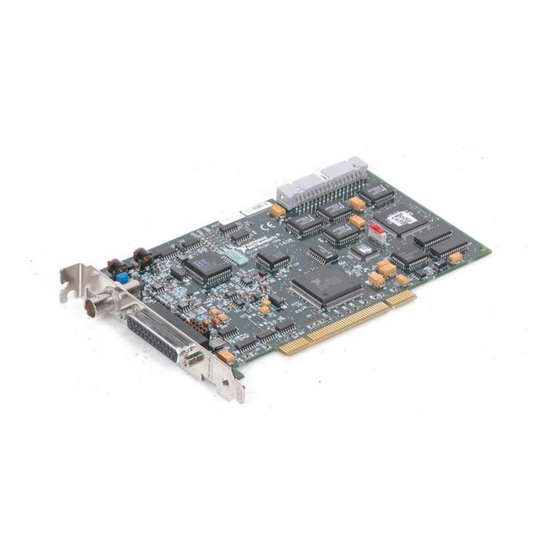
Page 20: Figure 2-2. Pci-1408 Parts Locator Diagram
3 BNC Connector 6 Product Name 8 RTSI Bus Connector 2 25-Pin DSUB 4 W1 7 Serial Number 9 Logical Address Connector Switch (S1) 5 Assembly Number Figure 2-2. PCI-1408 Parts Locator Diagram © National Instruments Corporation IMAQ PCI/PXI-1408 User Manual... -
Page 21: Video0 Input Mode
Chapter 2 Configuration and Installation 1 W2, W3 3 BNC Connector 6 Serial Number 9 Logical Address Switch (S1) 2 25-Pin DSUB 4 W1 7 J2 10 Product Name Connector 8 J4 5 Assembly Number Figure 2-3. PXI-1408 Parts Locator Diagram VIDEO0 Input Mode VIDEO0 has two different input sources via a BNC connector or a 25-pin DSUB port and two different input modes—referenced single-ended (RSE) -
Page 22: External Clk And Synchronization Input Mode
RSE Mode (Default) b. DIFF Mode Figure 2-5. Configuring PCLK, VSYNC, HSYNC, and CSYNC with Jumper W3 © National Instruments Corporation IMAQ PCI/PXI-1408 User Manual... -
Page 23: Switch S1
Chapter 2 Configuration and Installation Switch S1 Switch S1 is unused and should always be in the ON position, as shown in Figure 2-6. Figure 2-6. Switch S1 Installation Note You must install the NI-IMAQ driver software before installing your 1408 device. For information on how to install NI-IMAQ, please see the Getting Started with Your IMAQ System document and your NI-IMAQ release notes. - Page 24 Screw the front panel of the PXI-1408 to the front panel mounting rails of the PXI or CompactPCI chassis. Visually verify the installation. Plug in and turn on the PXI or CompactPCI chassis. Your PXI-1408 is now installed. © National Instruments Corporation IMAQ PCI/PXI-1408 User Manual...
-
Page 25: Hardware Overview
RTSI bus triggers. Other features include internally generated or externally input CSYNC, HSYNC, VSYNC, and PCLK synchronization and clock signals. The block diagram in Figure 3-1 illustrates the key functional components of the 1408 device. © National Instruments Corporation IMAQ PCI/PXI-1408 User Manual... -
Page 26: Video Mux
Chapter 3 Hardware Overview RTSI Bus Trigger Control Four External Triggers and Mapping Circuitry External PCLK, VSYNC VSYNC, and HSYNC and HSYNC PCLK, HSYNC, VSYNC PCLK Genlock and External CSYNC CSYNC Synchronization Generated Acquisition and Circuitry PCLK, Region of Interest HSYNC, Control VSYNC... -
Page 27: 8-Bit Adc And Lut
(PCLK), horizontal synchronization (HSYNC), and vertical synchronization (VSYNC) multiplexer. The onboard genlock and synchronization circuitry can generate clock and synchronization signals or the signals can be received from the I/O connector. © National Instruments Corporation IMAQ PCI/PXI-1408 User Manual... -
Page 28: Rtsi Bus
Chapter 3 Hardware Overview RTSI Bus The seven trigger lines on the RTSI bus provide a flexible interconnection scheme between multiple 1408 devices as well as between any National Instruments DAQ devices and the 1408 device. Trigger Control and Mapping Circuitry The trigger control and mapping circuitry routes, monitors, and drives the external and RTSI bus trigger lines. -
Page 29: Pci Interface
Chapter 3 Hardware Overview PCI Interface The 1408 device implements the PCI interface with a National Instruments custom application-specific integrated circuit (ASIC), the PCI MITE. The PCI interface can transfer data at a maximum rate of 132 Mbytes/s in master mode, which maximizes the available PCI bandwidth. 1408 devices can generate 8-, 16-, and 32-bit memory read and write cycles, both single and multiple. -
Page 30: Acquisition Window Control
Chapter 3 Hardware Overview Acquisition Window Control You can configure numerous parameters on the 1408 device to control the video acquisition window. A brief description of each parameter follows: • Horizontal sync—HSYNC is the synchronization pulse signal produced at the beginning of each video scan line that keeps a video monitor’s horizontal scan rate in sequence with the transmission of each new line. -
Page 31: Programming Video Parameters
RS-170/NTSC video signals is 12.3 MHz, and the standard sampling rate for CCIR/PAL is 14.75 MHz. To correct for external pixel aspect ratio errors of up to ±9%, the VCO covers the range from approximately 11.0 to 16.5 MHz. © National Instruments Corporation IMAQ PCI/PXI-1408 User Manual... - Page 32 Chapter 3 Hardware Overview The 1408 device also includes a programmable line count, which you use to switch between RS-170/NTSC (525 lines) and CCIR/PAL (625 lines). In addition, the 1408 device supports any line count up to 1,024 lines for nonstandard video inputs. You can have up to 2,048 lines in interlaced mode by combining fields.
-
Page 33: Acquisition Modes
A/D sampling directly from the external connector. Note If you are using an interlaced camera in external lock mode, connect a FIELD signal to the external connector. See Chapter 4, Signal Connections, for more information. © National Instruments Corporation IMAQ PCI/PXI-1408 User Manual... -
Page 34: Signal Connections
National Instruments. Figure 4-2 shows the pinout of the 25-pin DSUB connector. Note Do not use the VIDEO0 connection on the 25-pin DSUB connector with the BNC connection. © National Instruments Corporation IMAQ PCI/PXI-1408 User Manual... -
Page 35: I/O Connector Signal Connection Descriptions
Chapter 4 Signal Connections VIDEO0–/GND VIDEO0+ VIDEO1– VIDEO1+ VIDEO2– VIDEO2+ VIDEO3– VIDEO3+ +5 V CSYNCIN–/Unused CSYNCIN+ VSYNCIN–/Unused VSYNCIN+ HSYNCIN–/Unused HSYNCIN+ PCLKIN–/Unused PCLKIN+ TRIG3/FIELD TRIG2 TRIG1 CSYNCOUT TRIG0 Figure 4-2. I/O Connector Pin Assignments I/O Connector Signal Connection Descriptions Table 4-1 describes each signal connection on the 25-pin DSUB connector. Table 4-1. - Page 36 GND is a direct connection to digital GND on the 1408 device. +5V is a fused connection to +5 V on the 1408 device that allows you to power external triggering circuitry with up to 100 mA. © National Instruments Corporation IMAQ PCI/PXI-1408 User Manual...
-
Page 37: Appendix A Specifications
Black reference ........Programmable (0–1.26 V in 64 20 mV steps at a gain of 1) White reference ........Programmable (0–1.26 V in 64 20 mV steps at a gain of 1) © National Instruments Corporation IMAQ PCI/PXI-1408 User Manual... - Page 38 Appendix A Specifications A/D Conversion Gray levels ..........256 (8 bit) Differential nonlinearity ......±1 LSB max RMS noise ..........< 0.5 LSB rms Signal-to-noise ratio .......48 dB typ Sampling rate ..........5 to 20 MHz, externally clocked Pixel aspect ratio........Programmable (VCO range 11.0 to 16.4 MHz) External Connections Trigger sense...........TTL Trigger level ...........Programmable (rising or falling)
- Page 39 BAR1 (64 KB) Expansion ROM........4 KB PCI master performance Ideal ..........133 Mbytes/s Sustained ......... 100 Mbytes/s Power Requirements Voltage ........... +5 V (1.34 A) +12 V (100 mA) –12 V (50 mA) © National Instruments Corporation IMAQ PCI/PXI-1408 User Manual...
- Page 40 Appendix A Specifications Physical Dimensions PCI-1408..........10.7 by 17.5 cm (4.2 by 6.9 in.) PXI-1408 .........10 by 16 cm (3.9 by 6.3 in.) Weight PCI-1408..........0.127 kg (0.28 lb.) PXI-1408 .........0.172 kg (0.38 lb.) Environment Operating temperature ......0–55 °C Storage temperature ........–20–70 °C Relative humidity ........5–90%, noncondensing MTBF .............181,259 h at 25 °C Emissions..........EN 55011:1991 Group 1 Class A...
-
Page 41: Custom Cables
This appendix lists specifications for building custom cables for your 1408 device. Cable Specification National Instruments offers cables and accessories for you to connect to video sources, trigger sources, or synchronization sources. However, if you want to develop your own cables, the following guidelines must be met: For the video inputs, use a 75 Ω... -
Page 42: Technical Support Resources
Technical Support Resources This appendix describes the comprehensive resources available to you in the Technical Support section of the National Instruments Web site and provides technical support telephone numbers for you to use if you have trouble connecting to our Web site or if you do not have internet access. - Page 43 If you have trouble connecting to our Web site, please contact your local National Instruments office or the source from which you purchased your National Instruments product(s) to obtain support. For telephone support in the United States, dial 512 795 8248. For...
-
Page 44: Glossary
– negative of, or minus 5 V signal ± plus or minus Ω Amperes. Analog-to-digital. Alternating current. acquisition window The image size specific to a video standard or camera resolution. © National Instruments Corporation IMAQ PCI/PXI-1408 User Manual... - Page 45 Glossary active line region The region of lines actively being stored. Defined by a line start (relative to the vertical synchronization signal) and a line count. active pixel region The region of pixels actively being stored. Defined by a pixel start (relative to the horizontal synchronization signal) and a pixel count.
- Page 46 (ADCs) for analog input and digital-to-analog converters (DACs) for analog output. Central processing unit. CSYNC Composite synchronization signal. A combination of the horizontal and vertical synchronization pulses. CSYNCIN Composite sync in signal. CSYNCOUT Composite sync out signal. © National Instruments Corporation IMAQ PCI/PXI-1408 User Manual...
- Page 47 Glossary Digital-to-analog. Digital-to-analog converter. An electronic device, often an integrated circuit, that converts a digital number into a corresponding analog voltage or current. Data acquisition. (1) Collecting and measuring electrical signals from sensors, transducers, and test probes or fixtures and inputting them to a computer for processing.
- Page 48 The nonlinear change in the difference between the video signal’s brightness level and the voltage level needed to produce that brightness. © National Instruments Corporation IMAQ PCI/PXI-1408 User Manual...
- Page 49 Glossary genlock Circuitry that aligns the video timing signals by locking together the horizontal, vertical, and color subcarrier frequencies and phases and generates a pixel clock to clock pixel data into memory for display or into another circuit for processing. Ground signal.
- Page 50 A file containing compiled object modules, each comprised of one of more functions, that can be linked to other object modules that make use of these functions. line count The total number of horizontal lines in the picture. Least significant bit. © National Instruments Corporation IMAQ PCI/PXI-1408 User Manual...
- Page 51 Multiplexer. A switching device with multiple inputs that selectively connects one of its inputs to its output. NI-IMAQ Driver software for National Instruments IMAQ hardware. noninterlaced A video frame where all the lines are scanned sequentially, instead of divided into two frames as in an interlaced video frame.
- Page 52 1.0, but typically it falls between 0.95 and 1.05, depending on camera quality. pixel clock Divides the incoming horizontal video line into pixels. © National Instruments Corporation IMAQ PCI/PXI-1408 User Manual...
- Page 53 Glossary pixel count The total number of pixels between two horizontal synchronization signals. The pixel count determines the frequency of the pixel clock. Phase-locked loop. Circuitry that provides a very stable pixel clock that is referenced to another signal, for example, an incoming horizontal synchronization signal.
- Page 54 Also called a grounded measurement system. RTSI bus Real-Time System Integration Bus. The National Instruments timing bus that connects IMAQ and DAQ boards directly, by means of connectors on top of the boards, for precise synchronization of functions.
-
Page 55: Video Line
Glossary trigger Any event that causes or starts some form of data capture. trigger control and Circuitry that routes, monitors, and drives external and RTSI bus trigger mapping circuitry lines. You can configure each of these lines to start or stop acquisition on a rising or falling edge. - Page 56 A representation of a color image used for the coding of NTSC or PAL video signals. The luma information is called Y, while the chroma information is represented by two components, U and V representing the coordinates in a color plane. © National Instruments Corporation G-13 IMAQ PCI/PXI-1408 User Manual...
- Page 57 B-1 external CLK and synchronization input optional equipment, 2-2 mode, 2-7 required cables, 2-1 external connection specifications, A-2 CompactPCI specifications, 1-2 external lock mode composite synchronization. See CSYNC. description, 3-9 © National Instruments Corporation IMAQ PCI/PXI-1408 User Manual...
- Page 58 Index video acquisition, 3-5 to 3-8 acquisition window control, field, for interlaced video signal, 3-7 3-6 to 3-7 FIFO buffer, 3-4 programming video parameters, formats supported, A-1 3-7 to 3-8 frame start conditions, 3-5 definition, 3-7 video mux, 3-2 frame/field selection, 3-5 horizontal count, 3-6 functional overview, 3-1 to 3-5 HSYNC...
- Page 59 3-7 pixel aspect ratio circuitry, 3-3 National Instruments application software, 1-3 to 1-6 pixel clock. See PCLK. National Instruments Web support, C-1 to C-2 pixels NI-IMAQ driver software, 1-4 active pixel region, 3-6 NVRAM, 3-5 horizontal count, 3-6...
- Page 60 A-1 software control of video acquisition, 3-5 video line, 3-6 software programming choices, 1-3 to 1-6 video mux, 3-2 National Instruments IMAQ Vision, 1-5 National Instruments IMAQ Vision Builder, 1-5 NI-IMAQ driver software, 1-4 specifications, A-1 to A-4...
- Page 61 3-8 W3 jumper, external CLK and scaling down, 3-8 synchronization input mode, 2-7 VIDEO0 signal Web support from National Instruments, avoiding 25-pin DSUB connector with C-1 to C-2 BNC connection (note), 4-1 online problem-solving and diagnostic input mode, 2-6 to 2-7 resources, C-1 VIDEO0±...
Need help?
Do you have a question about the IMAQ PCI-1408 and is the answer not in the manual?
Questions and answers