Table of Contents
Advertisement
USER GUIDE AND SPECIFICATIONS
PCI/PXI/PCIe-6509
This document contains information about using the PCI-6509, PXI-6509, and PCIe-6509 data
acquisition devices with the NI-DAQmx driver software.
For information about using the USB-6509 device, refer to the NI USB-6509
Note
User Guide and Specifications document.
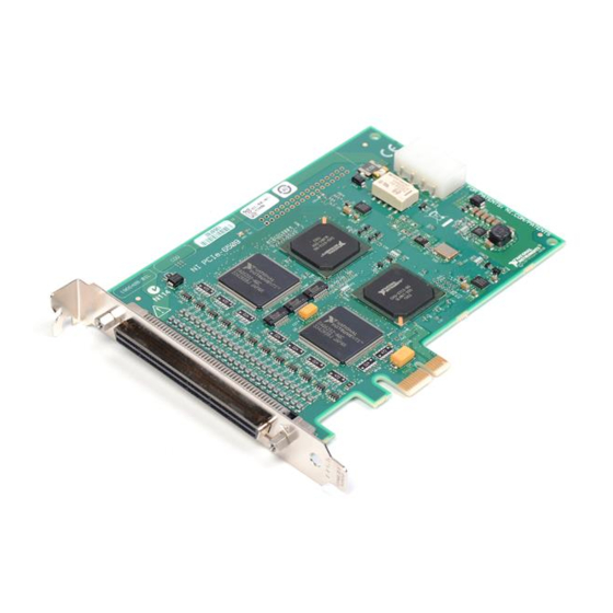
The NI 6509 is a 96-bit, high-drive digital input/output (DIO) device. The NI 6509 features
96 TTL/CMOS-compatible digital I/O lines, 24 mA high-drive output, digital filtering,
programmable power-up states, change detection, and a watchdog timer.
Contents
Safety Information .................................................................................................................... 2
Electromagnetic Compatibility Guidelines .............................................................................. 3
Configuration............................................................................................................................ 4
Programming Devices in Software................................................................................... 5
Functional Overview ................................................................................................................ 5
I/O Connector ........................................................................................................................... 6
Pin Assignments ............................................................................................................... 7
Signal Descriptions........................................................................................................... 9
Digital I/O................................................................................................................................. 11
Static DIO on NI 6509 Devices........................................................................................ 11
I/O Protection ................................................................................................................... 11
I/O Pull-Up/Pull-Down Resistors (PCIe-6509 Only)....................................................... 11
Signal Connections ........................................................................................................... 12
Protecting Inductive Loads............................................................................................... 13
Sinking and Sourcing Examples....................................................................................... 14
Power Connections ................................................................................................................... 15
+5 V Power Available at I/O Connector .......................................................................... 15
Disk Drive Power Connector (PCIe-6509 Only).............................................................. 15
Industrial DIO Features ............................................................................................................ 16
Digital Filtering ................................................................................................................ 16
Programmable Power-Up States....................................................................................... 18
Change Detection ............................................................................................................. 18
Watchdog Timer ............................................................................................................... 19
Accessories ............................................................................................................................... 20
Specifications............................................................................................................................ 20
Power Requirements......................................................................................................... 20
Digital I/O......................................................................................................................... 21
Digital Logic Levels (PCI/PXI-6509) .............................................................................. 21
Advertisement
Table of Contents

Related Manuals for National Instruments PCI-6509


Summary of Contents for National Instruments PCI-6509
-
Page 1: Table Of Contents
USER GUIDE AND SPECIFICATIONS PCI/PXI/PCIe-6509 This document contains information about using the PCI-6509, PXI-6509, and PCIe-6509 data acquisition devices with the NI-DAQmx driver software. For information about using the USB-6509 device, refer to the NI USB-6509 Note User Guide and Specifications document. -
Page 2: Safety Information
Safety Information This section contains important safety information that you must follow when installing and using National Instruments DIO devices. Do not operate the device in a manner not specified in this document. Misuse of the DIO device can result in a hazard. You can compromise the safety protection built into the DIO device if it is damaged in any way. -
Page 3: Electromagnetic Compatibility Guidelines
Working voltage is the highest rms value of an AC or DC voltage that can occur across any particular insulation. MAINS is defined as a hazardous live electrical supply system that powers equipment. Suitably rated measuring circuits may be connected to the MAINS for measuring purposes. PCI/PXI/PCIe-6509 User Guide and Specifications | © National Instruments | 3... -
Page 4: Configuration
Refer to the DAQ Getting Started guides for installation instructions and safety guidelines. • You must install the PCI-6509 into a slot that provides 3.3 V. Check that (PCI-6509 only) the 3.3 V LED (reference designator DS1—located on the visible edge of the underside of the installed device) is lit. -
Page 5: Programming Devices In Software
PCI Bus Data/Control 96 DIO 96 DIO Data/Control Watchdog Timer Interface Digital Filtering Change Detection Port 6 Port 7 Port 8 Port 9 Port 10 Configuration Control Port 11 PCI/PXI/PCIe-6509 User Guide and Specifications | © National Instruments | 5... -
Page 6: I/O Connector
Figure 2 shows the key functional components of the PCIe-6509. Figure 2. PCIe-6509 Block Diagram NI ASIC Programmable NI ASIC Power-Up States 48 DIO 48 DIO Watchdog Timer Digital I/O Digital Filtering Change Detection 100 MHz Data/Control Clock NI ASIC Programmable NI ASIC Power-Up States... -
Page 7: Pin Assignments
Figure 3 shows the pin assignments for the SH100-100-F cable when you connect it to the NI 6509 device. The naming convention for each pin is PX.Y, where X is the port (P) number, and Y is the line number. PCI/PXI/PCIe-6509 User Guide and Specifications | © National Instruments | 7... - Page 8 Figure 3. SH100-100-F Connector Pinout P2.7 P8.7 P5.7 P11.7 P2.6 P8.6 P5.6 P11.6 P2.5 P8.5 P5.5 P11.5 P2.4 P8.4 P5.4 P11.4 P2.3 P8.3 P5.3 P11.3 P2.2 P8.2 P5.2 P11.2 P2.1 P8.1 P5.1 P11.1 P2.0 P8.0 P5.0 P11.0 P1.7 P7.7 P4.7 P10.7 P1.6 P7.6...
-
Page 9: Signal Descriptions
P6.2 P9.2 P0.1 P3.1 P6.1 P9.1 P0.0 P3.0 P6.0 P9.0 +5 V +5 V Refer to the Signal Descriptions section for information about the signals available on this connector. PCI/PXI/PCIe-6509 User Guide and Specifications | © National Instruments | 9... - Page 10 Signal Descriptions Table 1 lists the signals and descriptions for all signals available on the NI 6509 device. Table 1. NI 6509 Signal Descriptions Signal Name Description 1, 3, 5, 7, 9, 11, 13, 15 P2.<7..0> Bi-directional data lines for P2.7 P2.0 port 2...
-
Page 11: Digital I/O
PCIe-6509 are connected to an NI ASIC that contains a weak pull-down resistor (47 k, typical), and each DIO line is connected to a software-selectable strong pull-up resistor (4.7 k, typical), as Figure 5 shows. PCI/PXI/PCIe-6509 User Guide and Specifications | © National Instruments | 11... -
Page 12: Signal Connections
Figure 5. PCIe-6509 Digital I/O Circuitry +5 V 4.7 k , typical Software Controlled NI ASIC Digital I/O Line I/O Protection 47 k , typical If you set the software to pull-down, the weak pull-down resistor in the NI ASIC pulls the DIO line low. -
Page 13: Protecting Inductive Loads
Figure 7. Limiting Flyback Voltages at the Inductive Load PX.Y Load NI 6509 Flyback Diode for Inductive Loads PCI/PXI/PCIe-6509 User Guide and Specifications | © National Instruments | 13... -
Page 14: Sinking And Sourcing Examples
Sinking and Sourcing Examples The following sections provide examples of driving a relay with no more than 24 mA, driving a relay with more than 24 mA, and driving a solid-state relay (SSR). Driving a Relay 24 mA Figures 8 and 9 show examples of connecting the NI 6509 to a relay that does not require more than 24 mA of current. -
Page 15: Power Connections
If the fuse is blown, the fuse LED (reference designator DS1—located on the visible edge of the underside of the installed device) is lit. In this case, return the device to NI for repair. PCI/PXI/PCIe-6509 User Guide and Specifications | © National Instruments | 15... -
Page 16: Industrial Dio Features
When to Use the Disk Drive Power Connector You can install the disk drive power connector if you want to increase the power supply on the +5 V terminal. However, it is not necessary to install the disk drive power connector for most applications. - Page 17 Depending on when the transition occurs, the filter may require up to two filter clocks—one full filter interval—to pass a transition. PCI/PXI/PCIe-6509 User Guide and Specifications | © National Instruments | 17...
-
Page 18: Programmable Power-Up States
The figure shows a rising (0 to 1) transition. The same filtering applies to falling (1 to 0) transitions. Programmable Power-Up States You can program the DIO lines on the NI 6509 to power up at a predefined state: input, high output, or low output. -
Page 19: Watchdog Timer
• The application disarms the watchdog timer and writes new values to the output lines. • The NI 6509 is reset. • The computer is restarted. PCI/PXI/PCIe-6509 User Guide and Specifications | © National Instruments | 19... -
Page 20: Accessories
The signal indicating an expired watchdog asserts continuously until the application disarms the watchdog timer. After the watchdog timer expires, the NI 6509 ignores any writes until the application disarms the watchdog timer. On the PCIe-6509, ports that are set to tristate cannot enter safe states of Note output when the computer enters a fault condition. -
Page 21: Power Requirements
100-pin female 0.050 series SCSI Pull resistor (PCIe-6509 only) Pull-up resistor 4.7 k, typical Pull-down resistor 47 k, typical Input voltage protection (PCIe-6509 only) ±20 V on up to two pins, maximum PCI/PXI/PCIe-6509 User Guide and Specifications | © National Instruments | 21... -
Page 22: Digital Logic Levels (Pci/Pxi-6509)
Digital Logic Levels (PCI/PXI-6509) Input Signals The maximum input logic high and output logic high voltages assume a Vcc supply voltage of 5.0 V. Given a Vcc supply voltage of 5.0 V, the absolute maximum voltage rating for each I/O line is –0.5 V to 5.5 V with respect to GND. - Page 23 With the disk drive power connector installed, the current at the +5 V terminal is supplied by an external power source. In this case, the current at the +5 V terminal can be up to 1 A. PCI/PXI/PCIe-6509 User Guide and Specifications | © National Instruments | 23...
-
Page 24: Physical Characteristics
Physical Characteristics Dimensions (without connectors) PCI-6509 12.4 cm × 9.7 cm (4.9 in. × 3.8 in.) PXI-6509 16.0 cm × 10.0 cm (6.3 in. × 3.9 in.) PCIe-6509 14.2 cm × 10.4 cm (5.6 in. × 4.1 in.) Weight PCI-6509 70.9 g (2.5 oz) -
Page 25: Safety
Random vibration for nonoperating Class 3. CE Compliance This product meets the essential requirements of applicable European Directives as follows: • 2014/30/EU; Electromagnetic Compatibility Directive (EMC) • 2011/65/EU; Restriction of Hazardous Substances (RoHS) PCI/PXI/PCIe-6509 User Guide and Specifications | © National Instruments | 25... -
Page 26: Environmental Management
At the end of the product life cycle, all products must be sent to EU Customers a WEEE recycling center. For more information about WEEE recycling centers, National Instruments WEEE initiatives, and compliance with WEEE Directive 2002/96/EC on Waste and Electronic Equipment, visit ni.com/environment/... -
Page 27: Worldwide Support And Services
NI products/technology, refer to the appropriate location: Help»Patents in your software, the patents.txt file on your media, or the National Instruments Patents Notice at ni.com/patents. You can find information about end-user license agreements (EULAs) and third-party legal notices in the readme file for your NI product. Refer to the Export Compliance Information at ni.com/legal/export-compliance for the NI global trade compliance policy and how to obtain relevant HTS codes, ECCNs, and other import/export data.
Need help?
Do you have a question about the PCI-6509 and is the answer not in the manual?
Questions and answers