National Instruments IMAQ PXI-1407 User Manual
Hide thumbs
Also See for IMAQ PXI-1407:
- Setup and operation (4 pages) ,
- User manual (51 pages) ,
- User manual (54 pages)

Related Manuals for National Instruments IMAQ PXI-1407


Summary of Contents for National Instruments IMAQ PXI-1407
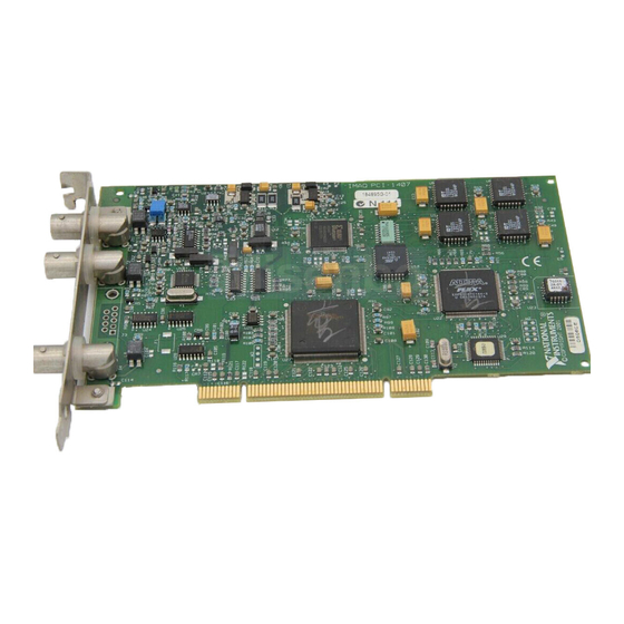
- Page 1 IMAQ ™ ™ IMAQ PCI/PXI -1407 User Manual High-Quality Monochrome Image Acquisition Boards for PCI, PXI, and CompactPCI Bus IMAQ PCI/PXI-1407 User Manual October 1999 Edition Part Number 322156B-01...
- Page 2 Switzerland 056 200 51 51, Taiwan 02 2377 1200, United Kingdom 01635 523545 For further support information, see the Technical Support Resources appendix. To comment on the documentation, send e-mail to techpubs@ni.com © Copyright 1998, 1999 National Instruments Corporation. All rights reserved.
- Page 3 Any action against National Instruments must be brought within one year after the cause of action accrues. National Instruments shall not be liable for any delay in performance due to causes beyond its reasonable control.
- Page 4 Classification requirements are the same for the Federal Communications Commission (FCC) and the Canadian Department of Communications (DOC). Changes or modifications not expressly approved by National Instruments could void the user’s authority to operate the equipment under the FCC Rules.
- Page 5 interference to radio or television reception, which can be determined by turning the equipment off and on, the user is encouraged to try to correct the interference by one or more of the following measures: • Reorient or relocate the receiving antenna. •...
- Page 6 Conventions The following conventions are used in this manual: ♦ The ♦ symbol indicates that the following text applies only to a specific product, a specific operating system, or a specific software version. This icon denotes a note, which alerts you to important information. This icon denotes a warning, which advises you of precautions to take to avoid being electrically shocked.
-
Page 7: Table Of Contents
Chapter 1 Introduction About Your PCI/PXI-1407 ....................1-1 Using PXI with CompactPCI..................1-2 Software Programming Choices ..................1-2 NI-IMAQ Driver Software ................1-4 National Instruments IMAQ Vision ..............1-5 IMAQ Vision Builder..................1-5 Integration with DAQ..................1-6 Vision and Motion...................1-6 Chapter 2 Installation What You Need to Get Started ..................2-1 Optional Equipment .......................2-2... - Page 8 Contents Chapter 4 Signal Connections BNC Connectors......................4-1 I/O Connector Signal Connection Descriptions..........4-2 Appendix A Specifications Appendix B Technical Support Resources Glossary Index Figures Figure 1-1. The Relationship between the Programming Environment, NI-IMAQ, and Your Hardware............. 1-3 Figure 1-2. NI-IMAQ Functions................
-
Page 9: About Your Pci/Pxi-1407
I/O line. If you require more advanced triggering or additional I/O lines (either digital or analog), you can use the PCI/PXI-1407 and NI-IMAQ with the National Instruments data acquisition (DAQ) product line. -
Page 10: Using Pxi With Compactpci
Using NI-IMAQ, the National Instruments image acquisition driver software, you can program your IMAQ board to acquire and save images. You can use NI-IMAQ with other National Instruments software for a complete image acquisition and analysis solution, as shown in Figure 1. -
Page 11: Figure 1-1. The Relationship Between The Programming Environment
Analysis and ROI Application Software LabVIEW BridgeVIEW ActiveX LabWindows/CVI (ComponentWorks) Driver Software NI-IMAQ NI-DAQ ValueMotion/ FlexMotion Hardware IMAQ ValueMotion/ FlexMotion Figure 1-1. The Relationship between the Programming Environment, NI-IMAQ, and Your Hardware © National Instruments Corporation IMAQ PCI/PXI-1407 User Manual... -
Page 12: Ni-Imaq Driver Software
The NI-IMAQ driver software performs all functions required for acquiring and saving images. The NI-IMAQ software does not perform any image analysis. For image analysis functionality, refer to the National Instruments IMAQ Vision section in this chapter. NI-IMAQ has both high-level and low-level functions for maximum flexibility and performance. -
Page 13: National Instruments Imaq Vision
Chapter 1 Introduction National Instruments IMAQ Vision IMAQ Vision is an image acquisition, processing, and analysis library of more than 200 functions for grayscale, color, and binary image display, image processing, pattern matching, shape matching, blob analysis, gauging, and measurement. -
Page 14: Integration With Daq
Introduction Integration with DAQ Any platform that supports NI-IMAQ also supports NI-DAQ and a variety of National Instruments DAQ boards, so your IMAQ device and NI-IMAQ development can integrate with National Instruments DAQ products. Vision and Motion With National Instruments IMAQ hardware and IMAQ Vision pattern... -
Page 15: Installation
IMAQ BNC-1 shielded, 75 Ω BNC cable for VIDEO (included with your PCI-1407) Your Pentium-based PCI, PXI, or CompactPCI computer running Windows 2000, Windows NT, or Windows 9x A video camera or other video source © National Instruments Corporation IMAQ PCI/PXI-1407 User Manual... -
Page 16: Optional Equipment
Pentium or better processor and an Intel 430 or 440 series or compatible PCI interface chipset. Optional Equipment National Instruments offers a variety of products for use with your PCI/PXI-1407, including other National Instruments DAQ devices for enhanced triggering, timing, or input/output. -
Page 17: Figure 2-1. How To Set Up Your Imaq System
NI-IMAQ functions. If you are using IMAQ Vision for LabWindows/CVI, read the documentation for IMAQ Vision for LabWindows/CVI. Figure 2-1. How to Set up Your IMAQ System © National Instruments Corporation IMAQ PCI/PXI-1407 User Manual... -
Page 18: Unpacking
• Remove the board from the package and inspect the board for loose components or any other signs of damage. Notify National Instruments if the board appears damaged in any way. Do not install a damaged board in your computer. - Page 19 Screw the front panel of the PXI-1407 to the front panel mounting rails of the PXI or CompactPCI chassis. Visually verify the installation. Plug in and turn on the PXI or CompactPCI chassis. Your PXI-1407 is now installed. © National Instruments Corporation IMAQ PCI/PXI-1407 User Manual...
-
Page 20: Hardware Overview
PCI bus. The board also includes a trigger for controlling the image acquisition. The block diagram in Figure 3-1 illustrates the key functional components of the PCI-1407 and PXI-1407. © National Instruments Corporation IMAQ PCI/PXI-1407 User Manual... -
Page 21: Video Buffer
Chapter 3 Hardware Overview Trigger Control Trigger HSYNC and VSYNC Acquisition and CSYNC Genlock SYNC Region-of-Interest Generator PCLK Control CSYNC Pixel Aspect Ratio Correction PCI Interface Video 8-bit A/D Gain and FIFO Scatter-Gather Buffer and LUT Offset DMA Controllers Video Figure 3-1. -
Page 22: Csync Mux
The PCI/PXI-1407 uses three independent onboard direct memory access (DMA) controllers. The DMA controllers transfer data between the onboard first-in first-out (FIFO) memory buffers and the PCI bus. Each of these controllers supports scatter-gather DMA, which allows the DMA © National Instruments Corporation IMAQ PCI/PXI-1407 User Manual... -
Page 23: Pci Interface
Chapter 3 Hardware Overview controller to reconfigure on-the-fly. Thus, the PCI/PXI-1407 can perform continuous image transfers to either contiguous or fragmented memory buffers. PCI Interface The PCI/PXI-1407 implements the PCI interface with a National Instruments custom application-specific integrated circuit (ASIC), the PCI MITE. -
Page 24: Acquisition Window Control
Picture aspect ratio—The picture aspect ratio is the ratio of the active pixel region to the active line region. For standard video signals like RS-170 or CCIR, the full-size picture aspect ratio normally is 4/3 (1.33). © National Instruments Corporation IMAQ PCI/PXI-1407 User Manual... -
Page 25: Programming Video Parameters
Chapter 3 Hardware Overview • Pixel aspect ratio—The pixel aspect ratio is the ratio between the physical horizontal size and the vertical size of the region covered by the pixel. An acquired pixel should optimally be square, thus the optimal value is 1.0, but typically it falls between 0.95 and 1.05, depending on camera quality. -
Page 26: Acquisition Modes
PCI/PXI-1407 receives an incoming video signal (composite or luminance) and an external CSYNC signal from an external connector. The PCI/PXI-1407 takes the incoming CSYNC signal and generates HSYNC, VSYNC, and PCLK signals. © National Instruments Corporation IMAQ PCI/PXI-1407 User Manual... -
Page 27: Signal Connections
PCI/PXI-1407 VIDEO, CSYNC and TRIG inputs. Use BNC cables to connect a camera to these inputs. You can configure the BNC connector only for referenced single-ended (RSE) mode. VIDEO CSYNC TRIG Figure 4-1. PCI/PXI-1407 BNC I/O Connectors © National Instruments Corporation IMAQ PCI/PXI-1407 User Manual... -
Page 28: I/O Connector Signal Connection Descriptions
Chapter 4 Signal Connections I/O Connector Signal Connection Descriptions Table 4-1 describes each signal connection on the three BNC connectors. Table 4-1. I/O Connector Signals Signal Name Description VIDEO VIDEO± allows for an RSE connection to the video channel. The incoming video signal must be positive, as shown in Figure 3-2, Positive Video Line. - Page 29 White reference ........Programmable (0–1.26 V) A/D Conversion Gray levels ..........256 (8 bit) RMS noise..........< 0.5 LSB rms Signal-to-noise ratio....... 48 dB typ Sampling rate ......... 5 to 20 MHz © National Instruments Corporation IMAQ PCI/PXI-1407 User Manual...
-
Page 30: Appendix A Specifications
Appendix A Specifications External Connections Trigger sense...........TTL Trigger level ...........Programmable (rising or falling) CSYNC sense .........TTL CSYNC level ..........Programmable (rising or falling) Minimum pulse width......50 ns (TTL) ..........2 V (TTL)..........0.8 V Internal Pixel Clock Generated frequency.......11.66 to 15.78 MHz Aspect correction for standard video sources......–5% to +7% Pixel jitter ..........<... - Page 31 Storage temperature ....... –20 to 70 °C Relative humidity ........5–90%, noncondensing MTBF............. 1,601,183 h at 30 °C Emissions ..........EN 55011:1991 Group 1 Class A at 10 m FCC Class A at 10 m © National Instruments Corporation IMAQ PCI/PXI-1407 User Manual...
- Page 32 Appendix A Specifications Functional shock (PXI only)....MIL-T-28800 E Class 3 (per Section 4.5.5.4.1) Half-sine shock pulse, 11 ms duration, 30 g peak, 30 shocks per face Operational random vibration (PXI Only) ..........5 to 500 Hz, 0.31 grms, 3 axes Nonoperational random vibration (PXI Only) ..........5 to 500 Hz, 2.5 grms, 3 axes Note Random vibration profiles were developed in accordance with MIL-T-28800E and...
-
Page 33: Technical Support Resources
Technical Support Resources This appendix describes the comprehensive resources available to you in the Technical Support section of the National Instruments Web site and provides technical support telephone numbers for you to use if you have trouble connecting to our Web site or if you do not have internet access. - Page 34 If you have trouble connecting to our Web site, please contact your local National Instruments office or the source from which you purchased your National Instruments product(s) to obtain support. For telephone support in the United States, dial 512 795 8248. For...
- Page 35 Positive of, or plus. – Negative of, or minus. Per. ± Plus or minus. Ω Ohm. Amperes. Analog-to-digital. Alternating current. acquisition window The image size specific to a video standard or camera resolution. © National Instruments Corporation IMAQ PCI/PXI-1407 User Manual...
- Page 36 Glossary active line region The region of lines actively being stored. Defined by a line start (relative to the vertical synchronization signal) and a line count. active pixel region The region of pixels actively being stored. Defined by a pixel start (relative to the horizontal synchronization signal) and a pixel count.
- Page 37 Composite synchronization signal. A combination of the horizontal and vertical synchronization pulses. Digital-to-analog. Digital-to-analog converter. An electronic device, often an integrated circuit, that converts a digital number into a corresponding analog voltage or current. © National Instruments Corporation IMAQ PCI/PXI-1407 User Manual...
- Page 38 Glossary Data acquisition. (1) Collecting and measuring electrical signals from sensors, transducers, and test probes or fixtures and inputting them to a computer for processing. (2) Collecting and measuring the same kinds of electrical signals with A/D or DIO boards plugged into a computer, and possibly generating control signals with D/A and/or DIO boards in the same computer.
- Page 39 Graphical user interface. An intuitive, easy-to-use means of communicating information to and from a computer program by means of graphical screen displays; GUIs can resemble the front panels of instruments or other objects associated with a computer program. © National Instruments Corporation IMAQ PCI/PXI-1407 User Manual...
- Page 40 Glossary Hour. hardware The physical components of a computer system, such as the circuit boards, plug-in boards, chassis, enclosures, peripherals, cables, and so on. HSYNC Horizontal synchronization signal. The synchronization pulse signal produced at the beginning of each video scan line that keeps a video monitor’s horizontal scan rate in step with the transmission of each new line.
- Page 41 See luma. Look-up table. Table containing values used to transform the gray-level values of an image. For each gray-level value in the image, the corresponding new value is obtained from the look-up table. © National Instruments Corporation IMAQ PCI/PXI-1407 User Manual...
- Page 42 Multiplexer. A switching device with multiple inputs that selectively connects one of its inputs to its output. NI-IMAQ Driver software for National Instruments IMAQ hardware. noninterlaced A video frame where all the lines are scanned sequentially, instead of divided into two frames as in an interlaced video frame.
- Page 43 CompactPCI specification by adding instrumentation-specific features. Random-access memory. real time A property of an event or system in which data is processed as it is acquired instead of being accumulated and processed at a later time. © National Instruments Corporation IMAQ PCI/PXI-1407 User Manual...
- Page 44 Also called a grounded measurement system. RTSI bus Real-Time System Integration Bus. The National Instruments timing bus that connects IMAQ and DAQ boards directly, by means of connectors on top of the boards, for precise synchronization of functions.
- Page 45 The level that defines what is white for a particular video system. See also black reference level. © National Instruments Corporation G-11 IMAQ PCI/PXI-1407 User Manual...
- Page 46 CSYNC CSYNC mux, 3-3 acquisition window control, 3-5 FIFO buffer, 3-3 CSYNC mux, 3-3 functional overview, 3-1 to 3-4 external acquisition mode, 3-7 gain and offset circuitry, 3-2 CSYNC signal (table), 4-2 © National Instruments Corporation IMAQ PCI/PXI-1407 User Manual...
- Page 47 DAQ, integrating with, 1-6 pixel aspect ratio circuitry, 3-3 scatter-gather DMA controllers, 3-3 to 3-4 trigger control, 3-4 video acquisition, 3-4 to 3-7 National Instruments web support, B-1 to B-2 acquisition window control, NI-IMAQ driver software, 1-4 3-5 to 3-6 programming video parameters,...
- Page 48 3-3 NI-IMAQ driver software, 1-4 specifications, A-1 to A-4 A/D conversion, A-1 environment, A-3 to A-4 Web support from National Instruments, external connections, A-2 B-1 to B-2 formats supported, A-1 online problem-solving and diagnostic internal pixel clock, A-2...
Need help?
Do you have a question about the IMAQ PXI-1407 and is the answer not in the manual?
Questions and answers