
Related Manuals for SKC 224-44XR


Summary of Contents for SKC 224-44XR
- Page 1 Universal Pump Cat. Nos. 224-44XR, 224-PCXR4, and 224-PCXR8 Service Manual SKC Inc. 863 Valley View Road Eighty Four, PA 15330-8619 Publication #1377 Rev 0910...
-
Page 3: Table Of Contents
Universal Pump Service Manual Table of Contents Introduction ..................................1 Performance Pro le ..............................1 Universal XR Sample Pump Functional Components ....................3 Pump Stack Assembly ............................3 Pulsation Dampener Assembly ..........................3 Regulator Assembly .............................. 3 Flowmeter Assembly ............................. 3 Filter Assembly .............................. -
Page 5: Introduction
Power Supply: Plug-in ba ery pack, rechargeable NiCad 2.0-Ah capacity, 6.0 V, UL Listed Charging Time: 6 to 8.5 hrs with PowerFlex Charger (with SKC approved charger) Operating Temp: 32 to 113 F (0 to 45 C) Storage Temp: -40 to 113 F (-40 to 45 C) - Page 6 Universal Pump Service Manual Performance Pro le (cont.) Use only SKC-approved parts to ensure reliable performance. Failure to do so voids UL Listing for intrinsic safety and any warranty. These additional features are found on the PCXR4 and the PCXR8...
-
Page 7: Universal Xr Sample Pump Functional Components
Universal Pump Service Manual Universal XR Pump Functional Components The Universal XR Pump systems consists of fi ve basic assemblies: Pump Stack Assembly The pump stack contains two silicone diaphragms driven by a DC motor and low-pressure positive-acting valves. The pump mechanism is sealed to protect it from dust. -
Page 8: Lcd
UL-Listed ba ery pack manufactured specifi cally for Universal XR sample pumps. Do not charge in hazardous locations. Use only an SKC-approved charger designated for this model to ensure reliable performance. Failure to do so voids any warranty. -
Page 9: Functional Testing
Power adapter cables (Cat. Nos. P8000, P8001, and P8005) and ba ery adapter cables (Cat. Nos. P8010 and P8013) are available from SKC. See Figures 9 and 10 and contact SKC to order. -
Page 10: Testing Flow Range Compensation
The Calibration Sheet Addenda in this manual can be used to document this testing. Compensation is factory preset. SKC recommends that compensation be checked periodically during routine maintenance to assure pump accuracy. Flow compensation will need to be reset if non-factory repairs have been made (see Pump Reassembly, Se ing Flow Compensation). -
Page 11: Pump Disassembly
Universal Pump Service Manual Pump Disassembly Tools • Universal XR Series pump • Needle nose pliers • Dual-ball rotameter, valve, • Phillips head screwdriver • Small at-head screwdriver magnehelic gauge connected with • Small Allen wrench • Water manometer tubing in line and in order •... -
Page 12: Checking Pumping Operation
Remove the motor/eccentric assembly from the pump housing (see Pump Disassembly, Disassembling the Stack, Steps 5 and 6). Because it is very diffi cult to determine the source of leaks in the bo om half stack, SKC recommends complete replacement with Cat No. P21251 (does not include a pressure switch assembly). A er replacing the half stack with a new one, perform functional testing (see Functional Testing). -
Page 13: Disassembling The Stack
Universal Pump Service Manual 2. A ach the fi lter housing inlet (Figure 1, #9) to the outlet of the magnehelic gauge. Ensure magnehelic gauge reads minimum back pressure. 3. Turn on the pump and adjust the fl ow adjust pot on the pump (Figure 1, #7) until the dual-ball rotameter reads 1500 ml. -
Page 14: Checking The Motor
Universal Pump Service Manual 8. Separate the bo om valve plate from the pump housing. 9. Remove the fi ve screws on the top valve plate (Figure 2, #6 and 5). One screw is shorter than the rest and must be replaced in the same hole from which it was removed (Figure 2, #13). 10. -
Page 15: Pump Reassembly
Universal Pump Service Manual Pump Reassembly Tools • Universal XR Series pump (disassembled) • Pliers • Dual-ball rotameter, valve, • Phillips head screwdriver • Needle nose pliers magnehelic gauge connected • Small at-head screwdriver • Thin wooden stick with tubing in line and in order •... -
Page 16: Setting The Flow Compensation
27. Set the fl ow compensation (see Reassembly, Se ing Flow Compensation). Setting Flow Compensation Compensation is factory preset. SKC recommends that compensation be checked periodically during routine maintenance to assure pump accuracy. Flow compensation will need to be reset if non-factory repairs have been made. Do not set fl ow compensation unless the ba ery voltage is at least 6.1 volts. -
Page 17: Replacing The Back Pump Case
3. Replace four screws and tighten in an alternating fashion. 4. Check for leaks (see Functional Testing, Initial Leak Check). * Replace with new O-ring only as needed (SKC Cat. No. P22409 [3 fi lters, 3 O-rings]). Replacing the Battery Pack 1. -
Page 18: Troubleshooting
Replace the control board. Replacement Control Board Cat. Nos. P22433U (PCXR8) or P22433T (PCXR4). Use only SKC-approved parts to ensure reliable performance. Failure to do so voids the UL Listing for intrinsic safety and any warranty. - Page 19 P22433T [PCXR4]). • Use a known good control board, stack, and motor when troubleshooting. SKC also recommends that a power supply be used for all testing. Connect it directly to the ba ery connector on the control board a er removing the ba ery pack.
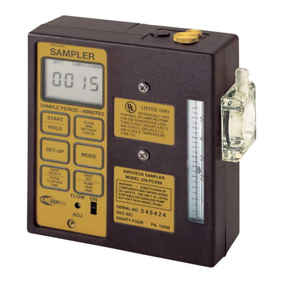
- Page 20 Universal Pump Service Manual Diagrams/Part Description for Figure 1 Use only SKC-approved parts to ensure reliable performance. Failure to do so voids UL Listing for intrinsic safety and any warranty. No. Description LCD: Displays indicators for all sampler functions. Low Compensation (Pot A): Adjusts factory-set fl ow compensation. Access screw helps reduce accidental contact or tampering.
-
Page 21: Figures
Universal Pump Service Manual Figure 1... - Page 22 Diaphragm/Yoke Assembly P22417H Motor/Eccentric Assembly P22417M Pressure Switch Assembly (PCXR4, PCXR8) P22417E Bottom Plate Assembly (224-44XR) P22417W Screws (2 long screws that hold top half stack to — — — bottom half stack O-rings Short Valve Plate Screws (must be replaced...
- Page 23 Universal Pump Service Manual Figure 3 Description Cat. No. Keypad (PCXR8) P22433P Keypad (PCXR4) P22433N Cap Screws (set of 2) (PCXR8, PCXR4, 224-44XR) P22417B Case Parts (excluding Battery Case) P21411 Control Board (PCXR8) P22433U Control Board (PCXR4) P22433T Control Board (224-44XR)
- Page 24 Universal Pump Service Manual Figure 4 - Pump Board in Pump Wires to Stack: Brown Orange Yellow Wires to Stack Red or Yellow Brown or Orange Shown: 44XR control board Description Screws with washers in place Battery Connector with screw V Jumper (voltage) I Jumper (current) Shown: PCXR8 control board...
- Page 25 MODEL 224-PCXR8 WARNING - SUBSTITUTION OF DIGIT DIGIT COMPONENTS MAY IMPAIR INTRIN SELECT SIC SAFETY. USE ONLY UL LISTED PORTABLE AIR SAMPLING PUMP TOTAL PUMP BATTERY PACK MODEL P21661 ELAPSED TIME TIME SERIAL NO. FLOW SKC INC. EIGHTY FOUR 15330...
- Page 26 Universal Pump Service Manual Figure 7 - Motor and Yoke Assembly Description Ensure that the yoke is parallel to motor counterweight Motor/Eccentric assembly Diaphragm/Yoke assembly Valve plate assemblies Set-screws O-rings Figure 8 - Pump Stack in Case No. Description Pump inlet Filter housing including O-ring and lter Discharge air cap screw covering exhaust port Regulator pressure adjustment cap covering...
- Page 27 Universal Pump Service Manual Figure 9 - Power Adapters Universal Power Adapter Power Adapter Cat. No. P8005 Cat. No. P8000 (requires Cat. No. P8000) (required for use with Cat. No. P8005) Multi-purpose Power Adapter Cat. No. P8001...
- Page 28 Universal Pump Service Manual Figure 10 - Battery Adapters Universal Battery Adapter Cat. No. P8013 (requires Cat. No. P8010) Battery Adapter Cat. No. P8010 (required for use with Cat. No. P8013)
-
Page 29: Addenda
Addendum A 224-44XR, 224-PCXR4, and 224-PCXR8 (5 Cell) Pump Calibration Model ____________ Serial Number _____________ Date: _________ Settings Readings Flow BP” Minimum Flow Maximum 5000 5000 5000 5000 4750 5250 4000 4000 4000 4000 3800 4200 4000 3800 4200 3000... - Page 30 Addendum B 224-44XRM, 224-PCXR4M, and 224-PCXR8M (4 Cell) Pump Calibration Model ____________ Serial Number _____________ Date: _________ Settings Readings Flow BP” Minimum Flow Maximum 4000 4000 4000 4000 3800 4200 3000 3000 3000 3000 2850 3150 3000 2850 3150 3000 2850 3150 2500...
Need help?
Do you have a question about the 224-44XR and is the answer not in the manual?
Questions and answers