
Subscribe to Our Youtube Channel
Related Manuals for SIGLENT SDG6000X Series: SDG6022X


Summary of Contents for SIGLENT SDG6000X Series: SDG6022X
- Page 1 SDG6000X Series Pulse/Arbitrary Waveform Generator Service Manual SM0206X-E01A 06X-E01A...
- Page 3 Declaration SIGLENT products are protected by patent law in and outside of P.R.C. SIGLENT reserves the right to modify or change parts of or all the specifications or pricing policies at company’s sole decision. Information in this publication replaces all previously corresponding material.
-
Page 4: General Safety Summary
Avoid Circuit or Components Exposed Do not touch exposed contacts or components when the power is on. Do not Operate in Wet/Damp conditions Do not Operate in an Explosive Atmosphere Keep the Surface of the Instrument Clean and Dry WWW.SIGLENT.COM... -
Page 5: Safety Terms And Symbols
WARNING: Indicates an injury or hazard that may not immediately happen. CAUTION: Indicates a potential damage to the instrument or other property that might occur. Symbols used on the instrument. Symbols may appear on the instrument: Hazardous Protective Warning Earth Ground Power Voltage Earth Ground Switch WWW.SIGLENT.COM... -
Page 6: Table Of Contents
Warming up ........................55 Channel Adjustment ....................... 56 Frequency Response Adjustment ................61 TimeBase Calibration..................... 62 Chapter 4 Assembly Procedures ....................63 Security Consideration ......................63 List of Modules ......................... 64 Required Tools.......................... 64 Disassembly Procedures ...................... 65 Chapter 5 Troubleshooting....................... 71 WWW.SIGLENT.COM... - Page 7 FPGA Checking ........................78 Connector Checking ......................78 Check the Main Board ......................79 Voltage Checking......................79 ARM CPU System Checking ..................79 Quick Guide for General Failures..................80 Chapter 6 Maintenance........................81 Maintain Summary ........................81 Repackaging for Shipment ....................81 WWW.SIGLENT.COM...
- Page 8 ESD Precautions to avoid personal injuries or damage to the generator. Maintenance Chapter 6 provides information on maintenance, daily care and inspection of the instrument. The contact information is included at the end of the chapter in WWW.SIGLENT.COM...
- Page 9 All the description for function and performance in this document are according to the SDG6052X series generator, and apply to all generators in this series. The SDG6000X series contains the following types: Type Analog Bandwidth Channels SDG6022X 200 MHz SDG6032X 350 MHz SDG6052X 500 MHz WWW.SIGLENT.COM...
-
Page 10: The Sdg6000X Series Generator At A Glance
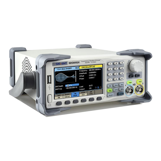
SDG6000X Service Manual The SDG6000X Series Generator at a Glance SIGLENT’s SDG6000X is a series of dual-channel Pulse/Arbitrary Waveform Generators that feature up to 500 MHz maximum bandwidth, maximum sample rate of 2.4 GSa/s and 16-bit vertical resolution. They also include... - Page 11 196 kinds of built-in arbitrary waveforms Standard interfaces: USB Host, USB Device (USBTMC), LAN (VXI-11, Socket, Telnet). Optional interface: GPIB 4.3” touch screen display for easier operation Note: All the specifications described in this manual refer to the SDG6052X. WWW.SIGLENT.COM...
-
Page 12: The Front Panel At A Glance
SDG6000X Service Manual The Front Panel at a Glance User Interface Knob Numeric Keyboard Host Arrow Keys Power Menu Function Channel Switch keys Keys Control WWW.SIGLENT.COM... - Page 13 Indicates the selected status and output configuration of the channels. Click on the screen here to switch to the corresponding channel. Click here again, shortcut menu of front panel's function keys will be shown: Mod, Sweep, Burst, Parameter, Utility and Store/Recall. WWW.SIGLENT.COM...
- Page 14 This mark indicates there is no LAN connection or LAN connection is unsuccessful. 6. Mode Icon The display will show different prompt messages based on the current phase mode. This icon indicates current phase mode is Phase-locked. This icon indicates current phase mode is Independent. WWW.SIGLENT.COM...
- Page 15 9. Modulation Parameters Area Shows the parameters of the current modulation function. Click on the screen here or select the corresponding menu, and use number keys or knob to change the parameter value. WWW.SIGLENT.COM...
-
Page 16: The Rear Panel At A Glance
AC Power Supply Input Interface Device WARNING: For protection from electric shock, the grounding power cord must not be defeated. If only a two-contact electrical outlet is available, connect the instrument’s chassis ground screw (see above) to a good earth ground. WWW.SIGLENT.COM... -
Page 17: Chapter 1 Specifications
40 MHz ~ 120 MHz ( included ), HiZ load Output Range 120 MHz ~ 160 MHz ( included ), Note HiZ load 160 MHz ~ 350 MHz ( included ), HiZ load 1.28 above 350 MHz, HiZ load WWW.SIGLENT.COM... - Page 18 2 ns edge , ≥ 10 ns width Note :The specification will be divided by 2 while applied to a 50 Ω load. Square Parameter Min. Typ. Max. Unit Condition & Note 1 μ Frequency 120 M SDG6052X, SDG6032X WWW.SIGLENT.COM...
- Page 19 Note :The specification will be divided by 2 while applied to a 50 Ω load. Arbitrary Wave Parameter Min. Typ. Max. Unit Condition & Note 1 μ Frequency 50 M setting range Waveform 20 M length Sampling rate 1 u 300 M Sa/s TrueArb mode 1.2 G Sa/s DDS mode WWW.SIGLENT.COM...
- Page 20 Supported by EasyIQ software Custom Output Range 1m Vrms , 50 Ω load 500 M SDG6052X Carrier 350 M SDG6032X frequency 200 M SDG6022X PRBS Parameter Min. Typ. Max. Unit Condition & Note 300 M SDG6052X, SDG6032X Bit rate 160 M SDG6022X WWW.SIGLENT.COM...
- Page 21 The amplitude of the generator ≥ ±10.5 ±11 ±11.5 threshold 3.2 Vpp or the DC offset ≥|2 VDC| Modulation Parameter Min. Typ. Max. Unit Condition & Note Carrier Sine, Square, Ramp, Arb Modulation Internal/External source Modulation Sine, Square, Ramp, Noise, Arb wave WWW.SIGLENT.COM...
- Page 22 Internal/External source Modulation Square with 50% duty cycle wave Keying While modulation source is “Internal” frequency Parameter Min. Typ. Max. Unit Condition & Note Carrier Sine, Square, Ramp, Arb Modulation Internal/External source Modulation Square with 50% duty cycle wave WWW.SIGLENT.COM...
- Page 23 Internal period 1 μ 1000 Trigger source Internal, External, Manual Gated source Internal/External Trigger delay Sweep Parameter Min. Typ. Max. Unit Condition & Note Carrier Sine, Square, Ramp, Arb Type Linear, Logarithmic Direction Linear: Up, Down, Up & Down Logarithmic: Up, Down WWW.SIGLENT.COM...
- Page 24 AC coupling impedance 10MHz Output Parameter Min. Typ. Max. Unit Condition & Note Frequency 10 M Synchronized to internal reference clock Amplitude HiZ load Ω Output impedance Auxiliary In/Out Trigger Input Parameter Min. Typ. Max. Unit Condition & Note -0.5 WWW.SIGLENT.COM...
- Page 25 100 - 240 Vrms (± 10%), 50 / 60 Hz 100 - 120 Vrms (± 10%), 400 Hz Power 32.5 Dual channels, Sine, 1 kHz, 10 Vpp, 50 Ω load consumption Display Parameter Min. Typ. Max. Unit Condition & Note Color depth WWW.SIGLENT.COM...
- Page 26 Non–operating 15000 altitude Calibration Parameter Min. Typ. Max. Unit Condition & Note Calibration year interval Mechanical Parameter Min. Typ. Max. Unit Condition & Note Dimensions W×H×D = 260.3 mm×107.2 mm×295.7 mm Net weight Gross weight Compliance IEC 61010-1:2010 EN61326-1:2013 WWW.SIGLENT.COM...
-
Page 27: Chapter 2 Quick Start
To Set the Symmetry of a Ramp Waveform To Configure a Pulse Waveform To Configure a Noise Waveform To Set the DC Voltage To Output a Built-In Arbitrary Waveform To Use the Built-In Help System WWW.SIGLENT.COM... -
Page 28: To Prepare The Generator For Use
Then, verify that whether the generator is turned on. Note: If the power-on self-test fails, the generator may stop and display a black screen. For solutions, please contact the nearest SIGLENT sales office or return the generator to SIGLENT for service. -
Page 29: To Adjust The Carrying Handle
SDG6000X Service Manual To Adjust the Carrying Handle To adjust the handle position of SDG6000X, please grip the handle by the sides and pull it outward. Then, rotate to the desired position. WWW.SIGLENT.COM... -
Page 30: To Set The Output Frequency
3. Input the desired frequency Use the digital keypad to input the value directly. Enter the value “20”, then press the corresponding softkey to select the desired unit. For example, press kHz. WWW.SIGLENT.COM... - Page 31 SDG6000X Service Manual Note: The desired numerical value can be modified using the knob and direction keys. WWW.SIGLENT.COM...
-
Page 32: To Set The Output Amplitude
HighLevel parameter. 2. Input the desired amplitude Use the digital keypad to input the value directly, enter the value “8”. Then press the corresponding softkey to select the desired unit. For example, press Vpp. WWW.SIGLENT.COM... - Page 33 SDG6000X Service Manual WWW.SIGLENT.COM...
-
Page 34: To Set The Dc Offset
LowLevel parameter. 2. Input the desired offset Use the digital keypad to input the value directly, enter the value “1”. Then press the corresponding softkey to select the desired unit. For example, press Vdc. WWW.SIGLENT.COM... - Page 35 SDG6000X Service Manual Note: The desired numerical value can be modified using the knob and direction keys. WWW.SIGLENT.COM...
-
Page 36: To Set The Duty Cycle Of A Square Waveform
The displayed duty is either the power-on value or the percentage previously selected. 3. Input the desired duty Use digital keypad to input the value directly, enter the value “80”, then press the corresponding softkey to select the desired unit “%”. WWW.SIGLENT.COM... - Page 37 SDG6000X Service Manual WWW.SIGLENT.COM...
-
Page 38: To Set The Symmetry Of A Ramp Waveform
The displayed symmetry is either the power-on value or the percentage previously selected. 3. Input the desired symmetry Use digital keypad to input the value directly, enter the value “60”, then press the corresponding softkey to select the desired unit “%”. WWW.SIGLENT.COM... - Page 39 SDG6000X Service Manual WWW.SIGLENT.COM...
-
Page 40: To Generate A Pulse Waveform
3. Set the Pulse Width Press the PulWidth/Duty softkey and then set the pulse width to 100 µs. The pulse width represents the time from the 50% threshold of the rising edge to the 50% threshold of the next falling edge. WWW.SIGLENT.COM... - Page 41 SDG6000X Service Manual 4. Set the Edge Time Press the Rise/Fall softkey and then set the rising edge to 10ns. 5. Set the Pulse Delay Press the Delay softkey and then set the delay time to 50 ns. WWW.SIGLENT.COM...
- Page 42 SDG6000X Service Manual WWW.SIGLENT.COM...
-
Page 43: To Generate A Noise Waveform
500mV Stdev and 1mV Mean. 1. Select the Noise function Press Waveforms→ Noise to select the noise function and output a noise waveform with the default parameters. 2. Set the Stdev Press the Stdev softkey and then set the Stdev to 500 mV. WWW.SIGLENT.COM... - Page 44 SDG6000X Service Manual 3. Set the Mean Press the Mean softkey and then set the mean to 1 mV. WWW.SIGLENT.COM...
-
Page 45: To Set The Dc Voltage
Press Waveforms → Page 1/2 → DC to select the DC function. 2. Set the DC Offset Use the digital keypad to input the value directly, enter the value “1”. Then press the corresponding softkey to select the desired unit. For example, press Vdc. WWW.SIGLENT.COM... - Page 46 SDG6000X Service Manual WWW.SIGLENT.COM...
-
Page 47: To Output A Built-In Arbitrary Waveform
1.Set the arbitrary waveform function Press Waveforms →Page 1/2→Arb Type → Built-In to enter the arbitrary waveform setting interface. 2.Set the Math waveform Press the Math softkey to display the mathematic waveforms as below. WWW.SIGLENT.COM... - Page 48 SDG6000X Service Manual 3. Output the exponential fall waveform Rotate the knob to select the ExpFall waveform and press the knob. The waveform is output with the present settings unless they are changed. WWW.SIGLENT.COM...
-
Page 49: To Use The Built-In Help System
Press Utility → System → Page 1/2 → Help to enter the following interface. You will see a list of help topics as below. Use Up and Down keys, then press Select to choose a Help topic. 2. Press “Cancel” or any function button to exit the help system WWW.SIGLENT.COM... -
Page 50: Chapter 3 Calibration
Accuracy specifications are valid only if adjustment is made at regular calibration intervals. Accuracy specifications are not valid beyond the1-year calibration interval. SIGLENT does not recommend extending calibration intervals beyond 2 years for any application. Adjustment is Recommended Specifications are valid only within the period from the last adjustment. -
Page 51: Test Considerations
The acceptance test results should be compared to the specifications given in chapter 1. After acceptance, repeat the performance verification tests within every calibration interval. If the instrument fails performance verification, adjustment or repair is required. WWW.SIGLENT.COM... -
Page 52: Dc Output Verification
-3.032 V ~ -2.968 V -10 V 10.102 V ~ -9.898 V 4. Remove the BNC cable to CH2 output and perform the same verification as CH1. 5. Compare the measured voltage to the spec range shown in the table above. WWW.SIGLENT.COM... -
Page 53: Ac Amplitude Verification
0.06236~0.06564 0.022 0.02078~0.02322 0.01 0.0089~0.0111 0.004 0.00296~0.00504 4. Remove the BNC cable to CH2 output and perform the same verification as CH1. 5. Compare the value measured from the DMM to the spec range shown in the table above. WWW.SIGLENT.COM... -
Page 54: Frequency Response Verification
150 MHz -2.3412~-1.7412 200 MHz -2.3412~-1.7412 250 MHz -2.3412~-1.7412 300 MHz -2.3412~-1.7412 350 MHz -2.3412~-1.7412 400 MHz -2.3412~-1.7412 450 MHz -2.3412~-1.7412 500 MHz -2.3412~-1.7412 4. Remove the BNC cable to CH2 output and perform the same verification as CH1. WWW.SIGLENT.COM... - Page 55 SDG6000X Service Manual 5. Compare the value measured from Power Meter to the spec range shown in the table above. WWW.SIGLENT.COM...
-
Page 56: General Adjustment Procedure
Vertical Accuracy Calibration which calibrates the amplitude at 10 kHz frequency. Frequency Counter Calibration which calibrates the trigger level of the counter. Frequency Response Adjustment which could properly compensate the amplitude as the frequency increases. TimeBase Calibration which calibrates the output frequency accuracy. WWW.SIGLENT.COM... -
Page 57: Software Environment
Before performing the adjustment procedures, let the generator and other test equipment warm up for at least 30 minutes in an ambient temperature between 18 ° C and 28 ° C. Adjustments performed prior to warm-up or beyond this temperature range may result in poor performance. WWW.SIGLENT.COM... -
Page 58: Channel Adjustment
Then Change the channel connection according to the prompt message. Note: If there is a problem in the process of the channel adjustment, you can separately perform the four parts mentioned above. After the feedback channel adjustment has been completed, perform a self adjustment. WWW.SIGLENT.COM... - Page 59 Self Adjust to make sure it is performed based on the best adjusting accuracy. 1. Connect the DMM, PC and SDG6000X generator as shown below: 2. Double click and run the script FeedbackAdjust.py prepared previously. The CH1 will be automatically turned on upon running of the script. WWW.SIGLENT.COM...
- Page 60 3. Once the “Self Adjust” begins, the generator turns to adjustment interface and the progress bar displays on the screen. In about 20 seconds it will reach 100%, which indicates completing of the self-adjust. The progress bar will disappear automatically after 2 seconds. WWW.SIGLENT.COM...
- Page 61 Compare the measured amplitude with the standard to obtain a set of compensation values. 1. Connect the DMM, PC and SDG6000X generator as shown below: 2. Double click and run the script VertAccCalib.py prepared previously. 3. Change the channel connection according to the prompt message. WWW.SIGLENT.COM...
- Page 62 1. Connect the PC and SDG6000X generator with a USB cable and connect the CH1 at the front panel to the counter port at the rear panel with a BNC cable, as shown below: 2. Double click and run the script FreqCounterCal.py prepared previously. WWW.SIGLENT.COM...
-
Page 63: Frequency Response Adjustment
Power Meter. After the generator completes the adjustment for CH1, the prompt message displays on the screen will prompt the operator to remove the BNC cable to CH2 to go on the adjustment. 4. After the two-channel adjustment is completed, please disconnect all the connections. WWW.SIGLENT.COM... -
Page 64: Timebase Calibration
TimeBase Calibration softkey. The timebase calibration interface is shown as the following. 3. Use the numeric keyboard or knob to adjust the DAC code to make the measured frequency to be closer to 10 MHz and select Accept to save the configuration. WWW.SIGLENT.COM... -
Page 65: Chapter 4 Assembly Procedures
ESD damage when servicing the instrument or any electronic device. Disassemble instruments only in a static-free work area. Use a conductive work area to reduce static charges. Use a conductive wrist strap to reduce static charge accumulation. Minimize handling. WWW.SIGLENT.COM... -
Page 66: List Of Modules
The following removable modules are listed in the order of performing disassembly procedures. Number of Module Module Handle Metal Shell and Rear Cabinet Front Cabinet Display Module Main Body Required Tools Use these tools to remove or replace the modules in the generator: T10 and T15 Torx screwdriver WWW.SIGLENT.COM... -
Page 67: Disassembly Procedures
1. Pull out the handle firmly from the two sides of the generator. 2. After removing 4PCS screws of the pad and 1PCS screw at the bottom of the generator’s case, remove the metal shell carefully from the main body to avoid being scratched. WWW.SIGLENT.COM... - Page 68 5PCS screws as shown in the following figure. 4. Separate the front panel from the main body of the generator. 5. Pull out the knob and then remove the screws attaching the hardware partition plate and the front cabinet screws. WWW.SIGLENT.COM...
- Page 69 SDG6000X Service Manual 6. Remove the keypad circuit board assembly. 7. Remove the 3PCS screws holding the screen bracket and remove the metal front panel. WWW.SIGLENT.COM...
- Page 70 9. Remove all the 9 screws affixed to the power supply board using the T10 Torx screwdriver. Separate the power supply board carefully from the main body of the generator in order to avoid being scratched by the sharp metal edge. WWW.SIGLENT.COM...
- Page 71 SDG6000X Service Manual 10. Pull out the connecting cable as shown in the following figure and then remove the fan, rear interface board, channel board and main board. WWW.SIGLENT.COM...
- Page 72 SDG6000X Service Manual Note: To assemble the generator, please follow these same steps in reverse order. WWW.SIGLENT.COM...
-
Page 73: Chapter 5 Troubleshooting
Required Equipments The equipment listed in the table below is required to troubleshoot the generator. Table 5-1 Required Equipments Equipment Critical Specifications Example Digital Multimeter DC Accuracy ±0.015% SDM3055 Oscilloscope 300 MHz Bandwidth SDS2304X WWW.SIGLENT.COM... -
Page 74: Channel Board Drawing
It mainly deals with the adjusting of signal parameters such as frequency, amplitude, and so on. Please refer to the following drawing to quickly locate the test points on the channel board for easy resolution of any problems encountered. WWW.SIGLENT.COM... - Page 75 SDG6000X Service Manual WWW.SIGLENT.COM...
-
Page 76: Main Board Drawing
CPU system. It completes the GUI function, controlling and configuration function of the channel board as well as the user interface. Please refer to the following drawing to quickly locate the test points on the main board for easy resolution of any problems encountered. WWW.SIGLENT.COM... -
Page 77: Check The Power Supply
20 percent. Table 5-3 Test Voltages of the Connector After Disconnected Voltage value Pins Error limit 20 V VH+(red) ± 30% -20 V VH-(white) ± 30% 6.5 V VL+(yellow) ± 30% -6.5 V VL-(blue) ± 30% WWW.SIGLENT.COM... - Page 78 However, this fuse will not fail ("open" or "blow") in normal power supply operation except when a significant overload occurs. Replace the entire main power supply if the input fuse fails. WWW.SIGLENT.COM...
-
Page 79: Check The Channel Board
If each tested voltage value is not within the corresponding spec range referring to table 5-4, the channel board is defective. Please return it to the factory for repair or contact SIGLENT. Table 5-4 Test Voltages of the Channel Board Test point... -
Page 80: 10 Mhz Clock Source Checking
Communication between the channel board and the Key CON_J8 and LCD board. CON_J12 Power supply of the fan. Table 5-5 explains the function of all the connectors on the channel board. It is important to ensure that all the connections are tight. WWW.SIGLENT.COM... -
Page 81: Check The Main Board
If each tested voltage value is within the corresponding specified range, then the main board is working normally. If the voltages are out of the specified range, please return it to the factory for repair or contact SIGLENT. Table 5-6 Test Voltages of the Main Board... -
Page 82: Quick Guide For General Failures
(4) Check if the connection between the power supply and the channel board is tight. (5) If the instrument still does not work normally, please contact SIGLENT. 2. Starts up with a dark screen: (1) Check the connection between the power supply and the channel board. -
Page 83: Chapter 6 Maintenance
In no case shall SIGLENT be liable for indirect, special or consequential damages. Repackaging for Shipment If the unit must be returned to SIGLENT for service or repair, be sure to: 1. Attach a tag to the unit identifying the owner and indicating the required service or repair. - Page 84 ADS7000 series, was launched in 2005, SIGLENT has become fastest growing manufacturer digital oscilloscopes. We firmly believe that today SIGLENT is the best value in electronic test & measurement. Headquarter: SIGLENT TECHNOLOGIES CO., LTD. Add: Bldg No.4 & No.5, Antongda Industrial Zone, 3rd Liuxian Road, Bao'an District, Shenzhen, 518101, China.
Need help?
Do you have a question about the SDG6000X Series: SDG6022X and is the answer not in the manual?
Questions and answers