SIGLENT SDG5000 series Service Manual
Function/arbitrary waveform generator
Hide thumbs
Also See for SDG5000 series:
- User manual (229 pages) ,
- Quick start manual (20 pages) ,
- Programming manual (83 pages)
Table of Contents
Advertisement
Quick Links
Download this manual
See also:
User Manual
Advertisement
Table of Contents

Related Manuals for SIGLENT SDG5000 series


Summary of Contents for SIGLENT SDG5000 series
- Page 1 Service Manual SDG5000 Series Function/Arbitrary Waveform Generator 2017 SIGLENT TECHNOLOGIES CO., LTD...
- Page 2 SDG5000 Service Manual...
-
Page 3: Guaranty And Declaration
Declaration SIGLENT products are protected by patent law in and outside of P.R.C. SIGLENT reserves the right to modify or change parts of or all the specifications or pricing policies at company‟s sole decision. Information in this publication replaces all previously corresponding material. -
Page 4: General Safety Summary
General Safety Summary Carefully read the following safety precautions to avoid person injury and prevent damage to the instrument or any products connected to it. To avoid potential hazards, please use the instrument as specified. Only qualified technician should perform service procedures Use Proper Power Line Use only the special power line of the instrument that approved by local state. -
Page 5: Safety Terms And Symbols
Safety Terms and Symbols Terms used on the instrument. Terms may appear on the instrument: DANGER: Indicates an injury or hazard that may immediately happen. WARNING: Indicates an injury or hazard that may not immediately happen. CAUTION: Indicates a potential damage to the instrument or other property that might occur. -
Page 6: Overview For The Document
Overview for the Document The document is for SDG5000 series arbitrary waveform generator, which will be mostly written as generator for short in the following text. The main contents described in this manual are: SDG5000 Series Generator at a glance This part introduces the main technology characteristics for SDG5000 generator. - Page 7 Convention for the whole Contents All the description for function and performance in this document are according to SDG5162 series generator, and apply to generator of the other types. The SDS5000 series contains the following types: Type Analog Bandwidth Channel SDG5082 80 MHz SDG5122...
-
Page 8: Sdg5000 Series At A Glance
SDG5000 Series at a Glance SDG5000 Series adopt the direct digital synthesis (DDS) technology, which can provide stable, high-precision, pure and low distortion signals. Its combination of excellent system features, easiness in usage and versatile functions makes this generator a perfect solution for your testing now and in the future. - Page 9 Remote control is realized using the USB cable. Multiple interfaces: USB host & device. USB-GPIB (IEEE-488) and LAN (option). Support the seamless connection with SIGLENT Series Digital Oscilloscopes; Being able to directly read and rebuild the stored waveform in the oscilloscopes.
-
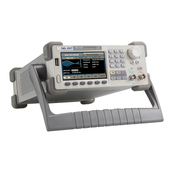
Page 10: The Front Panel At A Glance
The Front Panel at a Glance Description Description Power Switch Universal Knob LCD Display Numeric Keypad Menu Operation Waveform Key Function Keys Type Output Control Logo Direction Keys USB Host VIII SDG5000_ServiceManual_SM0205 0-E02A... - Page 11 The Front Panel Display at a Glance Channel 1 information Channel 2 information Function Status Waveform Waveform Display Parameters Waveform type operational key Figure1 Display Interface (Sine Wave is the default waveform) Here are the character definitions in this Service Manual: The signs for buttons in this manual are the same as the panel buttons.
-
Page 12: The Rear Panel At A Glance
The Rear Panel at a Glance 1. Ext Trig/Gate/FSK/Burst connector 2. 10MHz Output connector 3. USB Device connector 4. Power Socket 5. 10MHz Input connector 6. Sync Output connector 7. Modulation Input connector WARNING: For protection from electric shock, the grounding power cord must not be defeated. -
Page 13: Table Of Contents
General Safety Summary ......................II Safety Terms and Symbols ...................... III Overview for the Document ..................... IV SDG5000 Series at a Glance ....................VI The Front Panel at a Glance ....................VIII The Rear Panel at a Glance ...................... X Specification .......................... - Page 14 Check the Main Board ....................... 54 Voltage Checking ......................54 Mainboard Clock Checking..................54 DSP/CPLD Checking ....................55 Quick Guide for General Failures .................. 56 Maintenance ..........................57 Maintain Summary ......................57 Repackaging for Shipment ....................58 Contact SIGLENT ....................... 59 SDG5000_ServiceManual_SM0205 0-E02A...
-
Page 15: Specification
Specification These specifications apply to SDG5000 series Arbitrary Waveform Generator. To verify that an oscilloscope meets specifications, it must first meet the following conditions: The generator must have been operating continuously for fifteen minutes within the specified operating temperature. - Page 16 Frequency Specification Model SDG5082 SDG5122 SDG5162 Waveform Sine, Square, Ramp, Pulse, Noise, Arbitrary waveform 1μHz ~ 80MHz 1μHz ~120MHz 1μHz ~ 160MHz Sine 1μHz ~ 30MHz 1μHz ~ 40MHz 1μHz ~ 50MHz Square 1μHz ~ 20MHz 1μHz ~ 30MHz 1μHz ~ 40MHz Pulse 1μHz ~ 2MHz 1μHz ~ 3MHz...
- Page 17 Ramp Wave < 0.1% of output Peak value Linearity (typical value, 1 kHz, 1Vpp, symmetric 100%) Symmetry 0% ~ 100% Arbitrary Waveform Channel Waveform length 16kpts 512kpts Vertical resolution 14 bits 14 bits Sample rate 500MSa/s 500MSa/s Minimum Rise/Fall time 5ns(typical value)...
- Page 18 Waveform Output Channel CH1/CH2 50Ω (typical value) Impedance Protection short-circuit protection The BNC connectors for channel output, synchronous and modulation input are isolated to the Re Rack Earth, and the allowable voltage range is ± Isolation 42Vpk AM/DSB-AM Modulation(CH1/CH2) Carrier Sine, Square, Ramp, Arbitrary(except DC)...
- Page 19 Type linear/logarithmic Direction Up/ down Sweep time 1ms ~ 500s ± 0.1% Trigger source Manual, external, internal Burst(CH1/CH2) Waveform Sine, Square, Ramp, Pulse, Noise, Arbitrary (except DC) Carrier frequency 2mHz ~ 100MHz Type Count(1 ~ 1000000 cycles), infinite, Gated Start/Stop phase 0°...
- Page 20 REFCLK Input(10MHz ~ In) Connector The rear panel BNC connector, isolated to the Re Rack Earth and all the other connectors. Lock range 10MHz ± 50Hz Signal level 2.3Vpp ~ 3.3Vpp Lock Time < 2 s 1KΩ, AC coupling Input impedance REFCLK Input(10MHz ~ Out) Connector The rear panel BNC connector, rack (reference)
-
Page 21: General Specifications
General Specifications Display Display type 4.3‟TFT-LCD Resolution 480×RGB×272 Color 24bit Contrast(typical value) 500:1 Backlight intensity (typical ) 300cd/m Power 100~240 VACRMS, 45~66 Hz, CATII Voltage 100~127 VACRMS, 45~440 Hz, CATII Power < 30W Fuse 1.25A, 250V Environment Operation: 0° C ~ 40° C Environmental Temperature Non-operation: -20°... -
Page 22: Quick Start
Quick Start One of the first things you will want to do with your generator is to become acquainted with the front panel. We have written the exercises in this chapter to prepare the instrument for use and help you get familiar with some of its front-panel operations. -
Page 23: Prepare The Generator For Use
Then, verify that the generator is turned on. Note: If the power-on self test fails, the generator may stop with black screen. For solutions, please contact the nearest SIGLENT sales office or return the generator to SIGLENT for service. SDG5000 Service Manual... -
Page 24: Adjust The Carrying Handle
Adjust the carrying Handle To adjust the position, grasp the handle by the sides and pull outward. Then, rotate the handle to the desired position. Pull the handle ahead for easy carrying Pull the handle down SDG5000 Service Manual... -
Page 25: Set The Output Frequency
Set the Output Frequency The following steps show you how to change the frequency to 20 KHz. 1. Press the Store/Recall softkey Press the Store/Recall softkey to enter the parameter set interface. The waveform parameters including Frequency/Period, Amplitude/HighLevel, Offset/LowLevel and Phase are for you to modify using the numeric keypad. 2. - Page 26 Then press the corresponding softkey to select the desired unit. For example, press KHz. Note: You can also enter the desired value using the knob and direction keys. SDG5000 Service Manual...
-
Page 27: Set The Output Amplitude
Set the Output Amplitude The following steps show you how to change the amplitude to 8Vpp. 1. Press the Ampl/HLevel softkey The displayed amplitude is either the power-on value or the amplitude previously selected. When you change the function, the same amplitude is used if the current value is valid for the new waveform. -
Page 28: Set The Dc Offset
Set the DC offset The following steps show you how to change offset to 1Vdc. 1. Press the Offset/LLevel softkey The displayed offset is either the power-on value or the offset previously selected. When you change the function, the same offset is used if the current value is valid for the new waveform. -
Page 29: Set The Duty Cycle Of A Square Wave
Set the Duty Cycle of a Square Wave At power-on, the default duty cycle for square wave is 50%. You can adjust the duty cycle from 20% to 80% for output frequencies up to 50 MHz. The following steps show you how to change the duty cycle to 80%. 1. -
Page 30: Set The Symmetry Of A Ramp Wave
Set the Symmetry of a Ramp Wave At power-on, the Symmetry for Ramp wave is 50%. You can adjust the symmetry from 0% to 100%. The following steps show you how to change the symmetry to 60%. 1. Select the Ramp wave function Press Ramp button and then select the desired output frequency to 4MHz. -
Page 31: Generate A Pulse Waveform
Generate a Pulse Waveform You can set the generator to output a pulse waveform with variable width, edge time and delay time. The following steps show you how to generate a 500 µs pulse waveform with a pulse width of 100 µs, rise time of 8ns and delay time of 50 ns. - Page 32 4. Set the Edge Time Press the Rise/Fall softkey and then set the rise edge to 8 ns. 5. Set the Pulse Delay Press the Delay softkey and then set the delay time to 50 ns. SDG5000 Service Manual...
-
Page 33: Generate A Noise Waveform
Generate a Noise Waveform You can set the generator to output a noise waveform with Stdev and Mean. The following steps show you how to generate a noise waveform with 500mV Stdev and 1mV Mean. 1. Select the Noise function Press the Noise button to select the noise function and output a noise waveform with the default parameters. - Page 34 3. Set the Mean Press the Mean softkey and then set the mean to 1mV. SDG5000 Service Manual...
-
Page 35: Set The Dc Voltage
Set the DC Voltage You can set the DC Voltage feature from the Utility Menu, and then set a dc voltage as an “Offset” value. The following steps show you how to set a dc voltage with +1Vdc. 1. Select the Store/Recall function Press the Store/Recall button to enter the parameter setting interface. -
Page 36: Output A Built-In Arbitrary Waveform
Output a Built-In Arbitrary Waveform There are 36 built-in arbitrary waveforms stored in non-volatile memory. The following steps show you how to output the built-in “exponential fall” waveform from the front panel. 1. Set the arbitrary waveform function Press the button to select the arbitrary waveform function. -
Page 37: Use The Built-In Help System
Use the Built-In Help System The built-in help system is designed to provide context-sensitive assistance of some functions. A list of help topics is also available to assist you with several operations. 1. Read the help information for SDG5000 Press Help button in utility system, you will see a list of help topics as below. With easy operations on the front panel, you could read any help item you desired. -
Page 38: Calibration
Accuracy specifications will remain valid only if performance verification is made at regular calibration intervals. Accuracy specifications are not valid beyond the1-year calibration interval. SIGLENT does not recommend extending calibration intervals beyond 2 years for any application. -
Page 39: Recommended Test Equipment
Recommended Test Equipment The test equipment recommended for the performance verification and adjustment procedures is listed below. If the exact instrument is not available, substitute with an instrument of equivalent accuracy. Instrument Requirements Recommended Model DC volts Digital Multimeter(DMM) accuracy: 100ppm Agilent 34401A/34461A resolution: 100 μV Frequency:... -
Page 40: Performance Verification Test
Performance Verification Test The performance verification tests are recommended as acceptance tests when you first receive the instrument. The acceptance test results should be compared against the specifications given in chapter 1. After acceptance, you should repeat the performance verification tests at every calibration interval. If the instrument fails performance verification, adjustment or repair is required. -
Page 41: Dc Output Verification
DC Output Verification This test checks if the DC offset listed in the table below are within the specified range using a DMM. 1. Set the DMM to measure DC voltage. Connect the DMM to the channel 1 output of the generator as shown below. 2. -
Page 42: Ac Amplitude Verification
AC Amplitude Verification This test checks the ac amplitude output accuracy at the frequency of 10 kHz using a DMM. 1. Turn on the generator and choose CH1 as the operating channel. Set the Load to HiZ under the CH1/CH2 menu. 2. -
Page 43: Frequency Response Verification
Frequency Response Verification This test checks if the amplitude flatness is within the spec range using a PC controlled Power Meter. If you do not have a PC controlled Power Meter, simply ignore the USB connections shown. 1. Turn on the generator and choose CH1 as the operating channel. Set the Load to 50Ω... - Page 44 Voltage 2.5V CH1 (dBm) CH2 (dBm) Frequency Value Spec Range Value Spec Range 10KHz 11.8474 ~ 12.0281 11.8474 ~ 12.0281 100KHz -0.2 ~ V +0.2 -0.2 ~ V +0.2 1MHz -0.2 ~ V +0.2 -0.2 ~ V +0.2 5MHz -0.2 ~ V +0.2 -0.2 ~ V +0.2...
-
Page 45: General Adjustment Procedure
General Adjustment Procedure This chapter explains how to adjust the SDG5000 series generator for optimum operating performance. Channel Adjustment which includes three steps: feedback channel adjustment, channel self adjustment and vertical accuracy calibration. Feedback channel Adjustment which act as a standard calibration module, providing the accuracy assurance for Self Adjust. -
Page 46: Scripts For Calibration
Scripts for Calibration SIGLENT provides a free suite for calibrating SDG series products, in which all scripts are written in Python. Customers can download the package from the website and just run the scripts to complete the whole calibration process after some preparation works. -
Page 47: Channel Adjustment
Channel Adjustment The channel adjustment includes three parts: feedback channel adjustment, channel self adjustment and vertical accuracy calibration. 1. Turn on the generator. 2. Connect the DMM, PC and SDG5000 generator as shown below: 3. Double click and run the script ChannelAdjust.py prepared previously. Then change the channel connection according to the prompt message. - Page 48 Feedback Channel Adjustment The internal feedback channel receives the feedback signal from all the other channels that are performing self adjustment. This adjustment acts as a standard test module and must be performed prior to Self Adjust to make sure it is performed based on a best adjusting accuracy.
- Page 49 Channel Self Adjustment 1. This adjustment is for internal control channel and signal channel. Through feedback circuits of the feedback channel and signal channel, this adjustment helps to obtain the actual working performance for components from signal channels. After the feedback channel adjustment completed, disconnect the two BNC cables on channel 1 and channel 2.
- Page 50 Vertical Accuracy Calibration This adjustment aims to calibrate the amplitude at low frequency, using a DMM with high precision. The SDG5000 begins this portion of the calibration after the completion of the self adjustment process. It calibrates the Sine wave with a 10 kHz frequency and selects several amplitudes to calibrate.
-
Page 51: Frequency Response Adjustments
Frequency Response Adjustments This adjustment aims to obtain the actual frequency response characteristics of the signal channel, thus to perform appropriate compensation. Since the waveform amplitude will decrease as the input frequency increases, it is essential to compensate for the amplitude to match it to the frequency. This adjustment should be performed after the channel adjustment. -
Page 52: Assembly Procedures
Assembly Procedures This chapter describes how to remove the major modules from the SDG5000 series generator. To install the removed modules or replace new modules, please follow corresponding operating steps in reverse order. The following contents are what mainly included in this chapter: ... -
Page 53: List Of Modules
Minimize handling. Keep replacement parts in original static-free packaging. Remove all plastic, foam, vinyl, paper and other static-generating materials from the immediate work area. Use only anti-static solder suckers. List of Modules The following removable modules are listed in the order of performing disassembly procedures. -
Page 54: A View Of The Whole Instrument
A view of the whole Instrument The disassembly drawing are shown as below for you to disassemble the generator in right steps. Before disassembling, please cut the power to avoid any personal injuries or damages to inside components. Since some modules of the instrument are sharp, you should also take care while operating to prevent being scratched. -
Page 55: Removing The Handle
Removing the Handle Table 4-2 Removing the handle Removing steps: Pull down the handle hard from the two sides of the generator. To install the handle, please operate as the reverse steps. SDG5000 Service Manual... -
Page 56: Removing The Metal Shell And Rear Cabinet
Removing the Metal Shell and Rear Cabinet Rear Cabinet screw Table 4-3 Removing the Metal Shell and Rear Cabinet Removing steps: 1. Remove the two screws from the rear cabinet of the generator using a PH2 phillips screwdriver. 2. Remove the rear cabinet. 3. -
Page 57: Removing The Front Cabinet
Removing the Front Cabinet Front Cabinet screw BNC Connector Table 4-4 Removing the Front Cabinet Removing steps: 1. Remove the four front cabinet screws using the PH2 screwdriver. 2. Firmly pull up the two screws connected to the main board from the front panel BNC connectors. -
Page 58: Removing The Display Module
Removing the Display Module USB screw Keypad Board screw Metallic Support screw Table 4-5 Removing the display module screws Removing steps: 1. Remove the six screws fixed the keypad circuit board using the PH2 screw driver. 2. Remove the two screws fixed the USB module using the PH2 screwdriver. 3. -
Page 59: Removing The Main Body
Removing the Main Body Table 4-6 Disconnecting all the cables Table 4-7 Removing all the screws SDG5000 Service Manual... - Page 60 Removing steps: 1. Disconnect all cables from the main board and power supply board. 2. Remove all the 20 screws fixed the main board and power supply board using a the PH2 screwdriver. 3. Separate the main board and power supply board carefully from the main body of the generator to avoid being scratched by the sharp metal edge.
-
Page 61: Troubleshooting
This chapter explains the main checking procedures for these three boards by measuring the rated test points on them, thus to help you decide the reason for the failure you encounter while operating SDG5000 series arbitrary waveform generator. ESD Precautions... -
Page 62: Channel Board Drawing
Channel Board Drawing Channel board is a kind of signal conditioning board for output analog signal. It mainly works on the adjusting of signal parameters such as frequency, amplitude. Please refer to the following drawing to quickly locate the test points on the channel board for easy resolution of the failures you encounter. -
Page 63: Main Board Drawing
Main Board Drawing Main board is used to control and manage the whole internal system of the generator. It completes the GUI function, controlling and configuration function for channel board as well as man-machine interaction. Please refer to the following drawing to quickly locate the test points on the main board for easy resolution of the failures you encounter. -
Page 64: Check The Power Supply
If each tested voltage value is within the corresponding spec range referring to the table above, then the power supply works normally. Otherwise, it proves to be faulted, please return it to the factory to have it repaired or contact SIGLENT. SDG5000 Service Manual... - Page 65 Note: The main power supply provides an input fuse to protect against the danger of fire in the event of a failure of the power supply circuitry. However, this fuse will not fail ("open" or "blow") in normal power supply operation except that a significant overload occurs.
-
Page 66: Check The Channel Board
Otherwise, it proves to be faulted, please return it to the factory to have it repaired or contact SIGLENT. Table 5-3 Test voltages of the channel board... -
Page 67: Fpga Checking
FPGA Checking To check if the FPGA works normally, please look at the test point marked with FPGA_LED on the channel board drawing. The LED light twinkles at the frequency of 1Hz in normal case, if it cannot be lighted or twinkles at incorrect frequency, then the FPGA may be faulted. -
Page 68: Check The Main Board
Otherwise, it proves to be faulted, please return it to the factory to have it repaired or contact SIGLENT. Table 5-4 Test voltages of the main board... -
Page 69: Dsp/Cpld Checking
DSP/CPLD Checking DSP and CPLD respectively represent the main control chip and programmable logic device of the main board. Only when the corresponding codes loaded successfully, can the two chips work normally. Look at the DSP_LED/CPLD_LED light on the main board, which indicates the working state of DSP/CPLD chip. -
Page 70: Quick Guide For General Failures
(4) Check if the power connector is properly connected to the main board. (5) If the instrument still does not work normally, please contact SIGLENT. 2. The instrument starts up with a dark screen: (1) Check if the power connector is properly connected to the main board. -
Page 71: Maintenance
Maintenance Maintain Summary SIGLENT warrants that the products it manufactures and sells are free from defects in materials and workmanship for a period of three years from the date of shipment from an authorized SIGLENT distributor. If a product or CRT proves defective within the respective period, SIGLENT will provide repair or replacement as described in the complete warranty statement. -
Page 72: Repackaging For Shipment
Repackaging for Shipment If the unit needs to be shipped to SIGLENT for service or repair, be sure to: 1. Attach a tag to the unit identifying the owner and indicating the required service or repair. 2. Place the unit in its original container with appropriate packaging material for shipping. -
Page 73: Contact Siglent
Contact SIGLENT North America SIGLENT Technologies America, Inc 6557 Cochran Rd Solon, Ohio 44139 Tel: 440-398-5800 Toll Free:877-515-5551 Fax: 440-399-1211 info@siglent.com www.siglentamerica.com Headquarters SIGLENT TECHNOLOGIES CO., LTD. Blog No.4 & No.5, Antongda Industrial Zone, 3rd Liuxian Road, Bao‟an District, Shenzhen, 518101, China.
Need help?
Do you have a question about the SDG5000 series and is the answer not in the manual?
Questions and answers