
Related Manuals for Walinga Agri-Vac 3510

Summary of Contents for Walinga Agri-Vac 3510
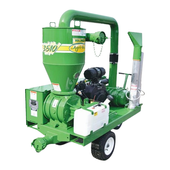
- Page 1 AGRI-VAC 3510 OPERATOR'S MANUAL and PARTS BOOK Model 3510 Gas and Electric TOUGH TO BEAT IN THE LONG RUN...
- Page 3 The above equipment and Operator’s Manual have been received by me and I have been thoroughly instructed as to care, adjustments, safe operation and applicable warranty policy. Date ___________________ Owner's Signature ________________________________________ 199 05042016 WHITE YELLOW PINK 3 Part Form Please Print WALINGA DEALER CUSTOMER...
- Page 5 Warranty Period The warranty period for the Walinga Warranty shall expire on the date that is the earlier of: two (2) years after the date of delivery to the original customer; or upon the expiration of five hundred (500) hours of operation; whichever date comes first.
- Page 6 The Walinga Warranty and all questions regarding its enforceability and interpretation are governed by the law of the country, state or province in which you purchased your Walinga equipment. The laws of some jurisdictions limit or do not allow the disclaimer of consequential damages.
- Page 7 Dear Customer, Thank you for choosing WALINGA PNEUMATIC CONVEYING SYSTEMS. For your convenience, should you require any information related to Parts, Service or Technical Engineering, please contact one of the following Walinga Personnel in Guelph at 1-888 925-4642 unless noted...
- Page 8 SERIAL NUMBER LOCATION ® ® Always give your dealer the serial numbers of your Walinga Inc. Agri-Vac when ordering parts or requesting service or other information. Serial number plates are located where indicated. Please mark the numbers in the spaces provided for easy reference.
- Page 9 NOTES:...
-
Page 10: Table Of Contents
TABLE OF CONTENTS SECTION DESCRIPTION PAGE Introduction ................1 ..................2 General Safety ...............3 Equipment Safety Guidelines.........4 Storage Safety ...............4 Safety Training..............5 Safety Signs ..............5 Preparation..............6 Installation Safety............6 Lock-Out Tag-Out Safety..........6 Operating Safety ............7 2.10 Maintenance Safety ............7 2.11 Electrical Safety .............8 2.12 Transport Safety.............8 2.13... -
Page 11: Introduction
Agri-Vac ® to complement your operation. This equipment has been designed and manufactured to meet the needs of the discriminating buyer for the efficient moving of grain. Safe, efficient and trouble free operation of your new Walinga ® Agri-Vac ®... - Page 12 ® Keep this manual handy for frequent reference and to pass on to new operators or owners. Call your Walinga dealer if you need assistance, information or additional copies of the manual. Contact your dealer for a complete listing of parts.
-
Page 13: General Safety
Do not modify the equipment in any way. fore servicing, adjusting, maintaining, repairing, Unauthorized modi cation may impair the func- cleaning or unplugging. (Safety lockout devices tion and/or safety and could a ect the life of the are available through your Walinga ® dealer parts equipment. department). -
Page 14: Equipment Safety Guidelines
2.2 EQUIPMENT SAFETY GUIDELINES In addition to the design and con guration of this Safety of the operator and bystanders is one of implement, including Safety Signs and Safety the main concerns in designing and developing a Equipment, hazard control and accident preven- machine. -
Page 15: Safety Training
2.4 SAFETY TRAINING 2.5 SAFETY SIGNS Safety is a primary concern in the design and man- Keep safety signs clean and legible at all times. ufacture of our products. Unfortunately, our e orts to provide safe equipment can be wiped out by a Replace safety signs that are missing or have be- single careless act of an operator or bystander. -
Page 16: Preparation
2.6 PREPARATION 2.7 INSTALLATION SAFETY Never operate the Agri-Vac ® and auxiliary equip- Disconnect and remove all mechanical locks, an- ment until you have read and completely un- chor chains and any other transport devices that derstand this manual, the auxiliary equipment would hinder or prohibit the normal functioning of Operator's Manual, and each of the Safety the Agri-Vac... -
Page 17: Operating Safety
2.9 OPERATING SAFETY 2.10 MAINTENANCE SAFETY Read and understand the Operator’s Manual and Good maintenance is your responsibility. Poor all safety signs before operating, maintaining, ad- maintenance is an invitation to trouble. Follow all justing or repairing the Agri-Vac ® operating, maintenance and operating instruc- tions in this manual. -
Page 18: Electrical Safety
Turn machine OFF, shut down and lock out pow- er supply (safety lockout devices are available Prevent res by keeping machine clean of accu- ® through your Walinga dealer parts department) mulated trash, grease and debris. and wait for all moving parts to stop before servic- ing, adjusting, maintaining or repairing. -
Page 19: Gas Motor Safety
2.16 GAS MOTOR SAFETY 16. DO NOT operate engine without a mu er. Inspect periodically and replace, if necessary. If engine is equipped with a mu er de ector, inspect pe- BEFORE STARTING ENGINE, READ AND UNDER- riodically and replace, if necessary with correct STAND THE OPERATING AND MAINTENANCE IN- de ector. -
Page 20: Safety Around Bins, Silos, Tanks Etc
SAFETY AROUND BINS,SILOS, TANKS AND BOOT PITS Working in and around bins, silos, and tanks and boot pits. Agri-Vac operators and all other personnel assisting should strictly adhere to the procedures outlined below before entering a storage structure. For additional details regarding these procedures, reference OSHA Standards, or your local regulations. -
Page 21: Employee Sign-Off Form
Inc. follows the general Safety Standards speci ed by the American Society of Agricultural and Biological Engineers (ASABE) and the Occupational Safety and Health Administration (OSHA). Anyone who will be operating and/or maintaining a Walinga ® built machine must read and clearly understand ALL Safety, Operating and Maintenance information presented in this manual. - Page 22 NOTES:...
- Page 23 SAFETY SIGN LOCATIONS The types of safety signs and locations on the equipment are shown in the illustrations that follow. Good safety requires that you familiarize yourself with the various Safety Signs, the type of warning and the area, or particular function related to that area, that requires your SAFETY AWARENESS.
- Page 24 The types of safety signs and locations on the equipment are shown in the illustrations that follow. Good safety requires that you familiarize yourself with the various Safety Signs, the type of warning and the area, or particular function related to that area, that requires your SAFETY AWARENESS. •...
- Page 25 The types of safety signs and locations on the equipment are shown in the illustrations that follow. Good safety requires that you familiarize yourself with the various Safety Signs, the type of warning and the area, or particular function related to that area, that requires your SAFETY AWARENESS. •...
- Page 26 The types of safety signs and locations on the equipment are shown in the illustrations that follow. Good safety requires that you familiarize yourself with the various Safety Signs, the type of warning and the area, or particular function related to that area, that requires your SAFETY AWARENESS. •...
-
Page 27: Operation
Review safety instructions annually. 4.1 TO THE NEW OPERATOR OR OWNER ® ® The Walinga Agri-Vac is designed to vacuum up It is the responsibility of the owner or operator to grain and move it in a stream of pressurized air. A high... -
Page 28: Machine Components
4.2 MACHINE COMPONENTS On the discharge side of the blower, the pressurized The air pump or blower is the key component in the ows through the airlock where it picks up a Agri-Vac ® and is driven by the: metered quantity of grain and moves it out the lines to the discharge cyclone. -
Page 29: Machine Break-In
4.3 MACHINE BREAK-IN 4.4 PRE-OPERATION CHECKLIST Although there are no operational restrictions on E cient and safe operation of the Walinga ® Agri-Vac ® the Agri-Vac ® when used for the rst time, it is requires that each operator reads and understands... -
Page 30: Machine Preparation
4.5 MACHINE PREPARATION Before the Agri-Vac ® can be used it must be set up and prepared for operation. When setting-up, follow this procedure: Clear the area of bystanders, especially small children. Be sure you select a spot that has su cient space to locate the machine and allows you to move around the unit to access the controls. -
Page 31: Controls
4.6 CONTROLS Before starting to work, all operators should familiarize themselves with the location and function of controls. Gas Engine: Read the engine manufacturers operator's manual before starting for more detailed instructions. a. Ignition Switch: This 3-position key-operated switch controls the electric power to the engine. - Page 32 Be familiar with the typical control box before starting. a. ON/OFF Switches: This control box is provided by Walinga ® can be used to operate the machine. Push the top green button in to turn the machine ON.
-
Page 33: Field Operation
Clear the area of all bystanders, especially small ing on top of material. children, before starting. • Review safety instructions annually. The Walinga ® Agri-Vac ® is used to pick up and move grain from one location to another on a stream of air. - Page 34 Starting: A. Electric: a. Depress green ON button on control box. B. Gas: a. Move choke lever into its OPEN position. b. Move the throttle lever midway be- tween the "slow" and "fast" positions. Turn the ignition key clockwise to Electric start the engine.
- Page 35 Operating: a. Insert nozzle into grain with airslide complete- ly open. b. Close airslide slowly until hose pulsates and then open slide an additional 1 ½ inches. Operate machine at this setting for ten min- utes to warm system before putting under full load.
- Page 36 10. Specialty Crops: When handling specialty products such as sun- ower seeds, lentils etc, it is recommended that the blower speed be reduced. This gives a gentler action through the machine. Pulse crops are sen- sitive to cracking so a gentler action is required to minimize cracking.
- Page 37 12. Optional Equipment: Several pieces of optional equipment are available to use with the Agri-Vac ® . The list includes but is not limited to: a. Pre-Cleaner: For removing abrasive material from the air ow to prevent it from going through the blower. Pre-Cleaner b.
- Page 38 SELF-DUMPING HOPPER BINS Self-Dumping Hopper Bins. DESCRIPTION PART NO 10 ga Steel Hopper, Self Dump C/W Safety Chains Capacity Steel Lid (Optional) (CY) (in) (in) (in) Part No 11-78297-6 11-78281-6 11-64331-6 11-78280-6 11-78298-6 11-78282-6 11-78196-6 11-78197-6 11-70845-6 11-106955-6 11-78299-6 11-78296-6 11-78324-6 11-78325-6 13.
-
Page 39: Transport
• Do not drink and operate. ® ® Walinga Agri-Vacs are designed to be easily and conveniently moved from location to location. When transporting, follow this procedure: Be sure all bystanders are clear of the machine. Disconnect air and grain lines and stow. -
Page 40: Storage
4.9 STORAGE STORAGE SAFETY • Store away from areas of human activity. • Store unit in a dry, level area. Support the base with planks if required. • Do not allow children to play on or around the ® stored Agri-Vac At the end of the season, the machine should be 4.10 CONVEYING OILSEEDS thoroughly inspected and prepared for storage. -
Page 41: Service
Blower Oil: • Follow good shop practices: Use Walinga ® Blower Oil part number 98-13813-5. Keep service area clean and dry. Model 3510 Be sure electrical outlets and tools are properly grounded. - Page 42 5.1.3 SERVICING INTERVALS 8 Hours or Daily Use the sight glasses to check the oil level in the blower reservoirs (2 locations). Schematic Blower (Typical) FIG. 14 RESERVOIRS Check engine uid levels (gas model only). a. Fuel b. Oil level FIG.
- Page 43 40 Hours or Weekly Grease airlock drive jack shafts and bearings. FIG. 16 JACK SHAFT BEARINGS Check drive belt and chain tension. Electric FIG. 17 BELT AND CHAIN TENSION Clean gas engine air lter. FIG. 18 AIR FILTER...
- Page 44 100 Hours or Annually Change the oil in the blower oil reservoirs (2 loca- tions) and clean head plate vent holes. Schematic Blower (Typical) FIG. 19 BLOWER Change engine oil - drain plug. Change engine oil lter. FIG. 20 ENGINE Change inline fuel lter.
- Page 45 Grease steering wheel bushing. FIG. 22 STEERING WHEEL BUSHING...
- Page 46 5.1.4 SERVICE RECORD See Lubrication and Maintenance sections for details of service. Copy this page to continue record. ACTION CODE: CLEAN GREASE CK CHECK CHANGE MAINTENANCE HOURS SERVICED BY 8 Hours or Daily CK Blower Oil Level (2 locations) CK Engine uid levels (2 locations) 40 Hours or Weekly G Airlock Drive Jack Shafts G Airlock Drive Bearings...
-
Page 47: Maintenance
5.2 MAINTENANCE By following a careful service and maintenance program on your machine, you will enjoy many years of trouble- free use. 5.2.1 CLEANING AIR CLEANER Review the Operator's Manual for the engine. Place all controls in neutral, stop engine, remove ignition key and wait for all moving parts to stop before maintaining. - Page 48 5.2.2 CHANGING ENGINE OIL AND FILTER Review the Operator's Manual for the engine. Place all controls in neutral, stop engine, remove ignition key and wait for all moving parts to stop before maintaining. Allow the engine to cool before changing the oil. Hot oil can cause burns if it contacts exposed skin.
- Page 49 5.2.3 CHANGING INLINE FUEL FILTER The gas model Agri-Vac ® is designed with an inline fuel lter to insure clean fuel goes to the engine. Change the inline fuel lter annually or more often if its gets dirty. To change the lter, follow this procedure: Place all controls in neutral, stop engine, remove ignition key and wait for all moving parts to stop before maintaining..
- Page 50 5.2.4 BELT TENSION AND ALIGNMENT Rotational power from the power source is transmitted to the blower and airlock through the belt drive (electric model). To obtain e cient transmission of power and good belt life, the belts must be properly tensioned and the pulleys aligned.
- Page 51 Pulley Alignment: a. Lay a straight-edge across the faces of the two pulleys. b. If the gap between the pulley and the straight- edge exceeds 1/16 inch (1.5mm), the pulleys must be realigned. Measure the distance the pulley needs to move.
- Page 52 Power Unit Base Adjustment: If the moving of pulleys does not align them, the base of the engine or motor can be adjusted for alignment. To move engine or motor follow this procedure: a. Determine the type of pulley mis-alignment. b.
- Page 53 5.2.5 CHAIN TENSION Rotational power from the jack shaft is transmitted to the airlock through the chain drive. To obtain e cient transmission of power and good chain life, the chain must be properly tensioned. Chains that are too tight will stretch and wear quickly or overload the bearings.
- Page 54 Oil in the reservoir should just ll the threads of the level plug hole. Add oil if low or allow the reservoir to drain if over- lled (Use Walinga ® Super Duty Blower Blower (Typical) Oil Part # 98-13813-5).
- Page 55 Install and tighten the drain plugs. Remove ll and level plug. ® g. Add Walinga Blower oil or equivalent to each reservoir until the oil is just starting to come out of the level plug hole or half way in sight glass.
- Page 56 5.2.7 AIRLOCK The airlock acts as a seal between the vacuum and pressure sides of the machine and is located at the bottom of the receiver tank. As the rotor turns, a pocket is lled with material when it points upward. As the pocket rotates, it is moved to the bottom and is moved into the pressure side of the system.
- Page 57 Tip Adjustment: a. Ensure that the unit power source cannot start up. Lock-out tag-out power source. b. Lift the receiver tank o the airlock. Loosen tip from rotor. d. Raise tip up and tighten bolts. e. Rotate the airlock and watch to make sure tip bends back slightly as it rotates into housing.
- Page 58 NOTES:...
-
Page 59: Trouble Shooting
If you encounter a problem that is di cult to solve, even after having read through this trouble shooting section, ® please call your Walinga dealer. Before you call, please have this Operator’s Manual and the serial number from your Agri-Vac ®... - Page 60 PROBLEM CAUSE SOLUTION Blower overheating. Not enough air ow. Open air slide nozzle to provide more air. Plugged screen. Clean screen. Low oil level. Add oil as required. Product damage. Poor connections. Tighten and seal all connections. Lines wearing. Eliminate elbows. Keep lines as straight as possible and provide a large radius for bends.
- Page 61 BLOWER PROBLEM CAUSE SOLUTION Low air volume. Slow speed. Check for slipping belts. Adjust belt tension as required. Piping blocked. Check inlet and outlet piping. Remove obstruction. Excessive pressure rise. Check inlet vacuum and discharge pressure and compare with recom- mended conditions.
- Page 62 NOTES:...
-
Page 63: Speci Cations
900 lbs. (410 kg) WHEELS 3 pneumatic (1 on swivel) 3 pneumatic (1 on swivel) Mounted on legs BLOWER #510 Walinga blower #510 Walinga blower #510 Walinga blower # 1210-4A steel housing, AIRLOCK # 1210 drop-thru cast iron # 1210 drop-thru cast iron... -
Page 64: Bolt Torque
BOLT TORQUE CHECKING BOLT TORQUE The tables shown below give correct torque values for various bolts and capscrews. Tighten all bolts to the torques speci ed in chart unless otherwise noted. Check tightness of bolts periodically, using bolt torque chart as a guide. - Page 66 NOTES:...
- Page 67 NOTES:...
- Page 68 9 INDEX PAGE PAGE Introduction ................1 Safety ................2 Battery Safety..............8 Electrical Safety...............8 Employee Sign-O Form .......... 11 Equipment Safety Guidelines ........4 Gas Motor Safety ............9 Operation ................17 General Safety ..............3 Field Operation ............23 Installation Safety............6 Controls................21 Lock-Out Tag-Out Safety..........6 Machine Break-In............
- Page 70 Operator’s Manual CORPORATE HEAD OFFICE: 5656 Highway 6N RR#5, Guelph, Ontario,N1H 6J2 PHONE: (888) 925-4642 FAX: (519) 824-5651 www.walinga.com AGRI-VAC MANUFACTURING FACILITY: 938 Glengarry Cres., Fergus, Ontario Canada N1M 2W7 Tel: (519) 787-8227 Fax: (519) 787-8210 DISTRIBUTION AND SERVICE CENTRES:...
Need help?
Do you have a question about the Agri-Vac 3510 and is the answer not in the manual?
Questions and answers