
Related Manuals for Metso NelesAce


Summary of Contents for Metso NelesAce
- Page 1 NelesAce™ BASIS WEIGHT CONTROL UNIT Installation, Maintenance and Operating Instructions...
-
Page 2: Table Of Contents
TYPE CODE ............18 READ THESE INSTRUCTIONS FIRST! These instructions provide information about safe handling and operation of the control unit. If you require additional assistance, please contact Metso’s Automation business or your authorized distributor or representative. SAVE THESE INSTRUCTIONS! Subject to change without notice. -
Page 3: General
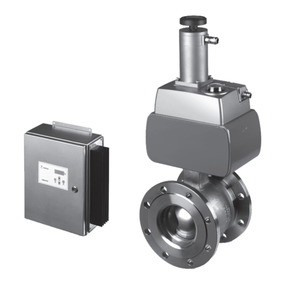
Pulse duration mode General view 24 VDC/10,5mA ® input pulse Metso NelesAce basis weight control system comprises a V- port segment valve, an actuator and a control unit. pulse to stepping motor The valve is a standard R-series V-port segment valve. - Page 4 8 ACE 71 en DN x 10 distance after the curve DN x 10 distance after the curve Fig. 3 Installing the valve into pipeline CONNECTOR PANEL CONTROL 24 VDC PE (EARTH) OPTION 2 OPTION 1 TIME DURATION GND TIME DURATION GND TIME DURATION CLOSE TIME DURATION CLOSE 8x0.5...
-
Page 5: Recycling And Disposal
8 ACE 71 en 1.4.3 Control unit NOTE: Step motor controller type GSP 92-70 Only authorized persons are permitted to carry out the Nominal power 200 W max. motor power electrical connections for the device. 230 V AC (option 110 V AC) 2 A, fuse T 2.5 A MOUNTING (110 V: 4.2 A, fuse T 5 A) -
Page 6: Commissioning
The following errors are indicated: NOTE: When replacing the existing basis weight valve with no supply voltage to limit switches. NelesAce it is recommended to you verify and, if neces- overheating of controller, >85 °C. sary, tune DCS parameters. ... -
Page 7: Modifying The Parameters
8 ACE 71 en MODIFYING THE PARAMETERS Basic functions IPCOMM program is a setup program for the controller. Once a connection has been established between the com- With the program the user can change every necessary puter and the controller, the user can carry out the configu- parameter. -
Page 8: Limitation Of The Motor Current
Changes can be carried out in the PLC-code window, pulses etc. Flow is controlled depending on the error Fig. 12 and Fig. 13. With the NelesAce delivery there is param- between actual and desired flow rate. The decision for step eter list which includes program listing. - Page 9 8 ACE 71 en 4.5.1 Changing pulse duration mode settings NOTE: In pulse duration command lines (move relative), don't change the Offset and Run frequencies! To change the step size, scroll the command (Prog.) line selection slider to 0 (or up to 3, see Table 3). ...
-
Page 10: Operating
MAINTENANCE and 100 % indicates an open valve. General NelesAce is a digital and modular device. This facilitates maintenance. The smallest step motor movements are impossible to distinguish from the movements of valve or shafts without special measuring instruments. For this rea-... -
Page 11: Replacement And Calibration Of Potentiometer And R/I Modulator
If the display shows - % continuosly, the current loop is or with another soft tool so as not to cause damage open. This can be the case if NelesAce is tested on the to the segment while hitting it. While the gap is of bench before connecting to DCS. - Page 12 8 ACE 71 en Table 6 Recommended preventive maintenance for NelesAce Estimated Part Part Id-code Part No Picture Actions in one year interval Actions in two years interval service Description hours / h H025874 50, 61 Potentiometer + Calibration Component change R/I modulator 1.1.
- Page 13 8 ACE 71 en The valve doesn't move acc. to automatic control Is LED 6 lit and Is control signal No Can valve be operated Check power supply. Fuse is faulty. Control unit is faulty. available at does it turn off when in MAN mode? Is LED 11 lit? Replace the fuse.
- Page 14 8 ACE 71 en Position display doesn't match with actual valve position . Does current from position Connector card is faulty. Is position transmitter transmitter match with Replace connector card. supply voltage 24 VDC? actual valve position? Actuator is faulty. Potentiometer is faulty.
-
Page 15: Assembly Drawings And Part Lists
8 ACE 71 en ASSEMBLY DRAWINGS AND PART LISTS Actuator 29 102 107 80 83 44 47 50 61 28 27 173 174 Part Description Available spare parts Recommended spare parts Mounting bracket Gear Flange Locking screw Locking washer Coupling Potentiometer belt roller Potentiometer belt Potentiometer... -
Page 16: Control Unit
8 ACE 71 en Control unit ZERO SPAN Part Description Available spare parts Recommended spare parts HST housing HST housing cover Bottom plate Side plate Lead in socket Heat sink Display card Connector card Controller Adhesive label... -
Page 17: Dimensions And Weights
8 ACE 71 en DIMENSIONS AND WEIGHTS 7.50 4.00 6.25 HAND WHEEL ø8 Actuator Dimensions, mm Weight, kg NC4L-50 NC4L-65 NC4L-80 NC4L-100 NC4L-150 NC4L-200 NC4L-250 1085 NC4L-300 1125 NC4L-350 1265 NC4L-400 1015 1370 NC4L-500 1110 1530 Size Actuator Dimensions, inch Weight, lb NC4L-50 2.95... -
Page 18: Type Code
8 ACE 71 en TYPE CODE SEGMENT VALVE RA AND RE FOR nelesACE 1. sign CV-CODE Standard CV, without sign 2. sign PRODUCT SERIES / DESIGN Wafer, reduced bore, Neles face-to-face lenght, Body PN50 / ANSI Class 300* Flanged, reduced bore, ISA S 75.04 and DIN/IEC 534 Part 3-2 3. - Page 19 8 ACE 71 en STEP MOTOR ACTUATOR nelesACE FOR BASIS WEIGHT CONTROL NC4L ND4KS2 1. sign PRODUCT SERIES / DESIGN Step motor actuator. NC4L Ambient temperature 0...+50 °C / +32...+122 °F, IP65 enclosure Applicable only with RA_W -serie valves. Step motor actuator.
- Page 20 8 ACE 71 en Metso Flow Control Inc. Europe, Vanha Porvoontie 229, P.O. Box 304, FI-01301 Vantaa, Finland. Tel. +358 20 483 150. Fax +358 20 483 151 North America, 44 Bowditch Drive, P.O. Box 8044, Shrewsbury, M A 01545, USA. Tel. +1 508 852 0200. Fax +1 508 852 8172 South America, Av.
Need help?
Do you have a question about the NelesAce and is the answer not in the manual?
Questions and answers