Table of Contents
Advertisement
Quick Links
Advertisement
Chapters
Table of Contents

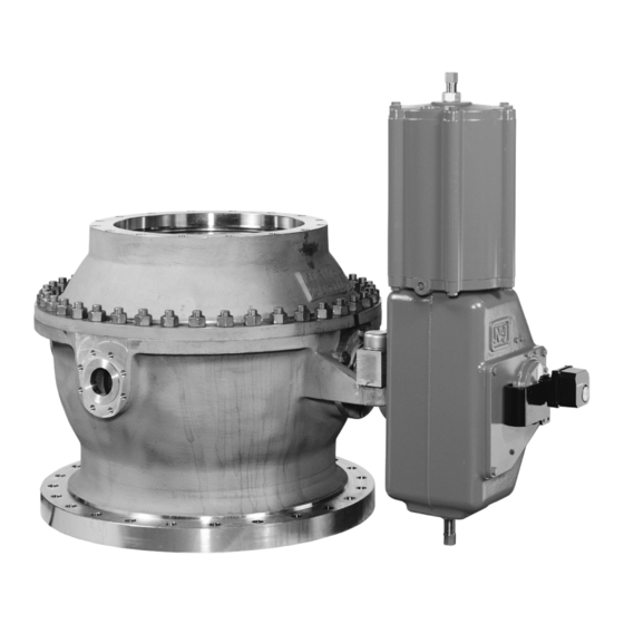
Summary of Contents for Metso Neles PZ Series
- Page 1 CAPPING VALVE Series PZ Installation, Maintenance and Operating Instructions...
-
Page 2: Table Of Contents
8 PZ 70 en Table of Contents GENERAL............3 Scope of the manual ......3 Valve construction........3 Valve markings........3 Specifications ......... 3 Valve performance ......... 3 Valve approval ........4 Recycling and disposal ......4 Safety precautions ......... 4 TRANSPORTATION, RECEPTION AND STORAGE............ -
Page 3: General
8 PZ 70 en GENERAL Scope of the manual This manual provides the essential information needed by users of PZ capping valves. If you require further information on actuators and instrumentation, see the separate installation, maintenance and operation Fig. 2 instructions for the various models. -
Page 4: Valve Approval
347 °F), causing possible ball surface damages. Protect yourself and the environment from poisonous Metso realizes that some mills may require a water or otherwise harmful substances. wash/spray to the ball surface and others may require a Otherwise, personal injury or damage to equipment water bed. -
Page 5: Transportation, Reception And Storage
8 PZ 70 en Mounting the valve on the digester CAUTION: Do not open the valve during cooking! CAUTION: Valve control must be arranged to ensure that the When handling the valve or the valve package, valve cannot be opened during cooking. Otherwise, bear in mind its weight! personal injury or damage to equipment may result. -
Page 6: Maintenance
8 PZ 70 en MAINTENANCE Ball and seating If the valve leaks, the probable cause is chips between General the ball and the seat. Before adjusting lifting springs (20), The valve does not require regular maintenance. It is wash and pool the ball surface with a water jet when valve recommended, however, that the seal of the gland partly open. -
Page 7: Valve Assembly
8 PZ 70 en 4.6.2 Ball seat The seat (4) is locked in its groove. If the seat is in order and there is no reason to suspect the condition of the seal (25), the seat need not be dismantled for servicing. Remove the seat as follows: ❑... - Page 8 8 PZ 70 en ❑ Set the body gasket (26) in place. The gasket must ator and loosen both tilting device nuts (18) by be replaced each time the valve is dismantled. 90°. When necessary, continue loosening the ❑ Install the tilting device. Replace the bearings nuts 90°...
-
Page 9: Installing The Actuator
8 PZ 70 en ❑ Fasten tight the gland packing nuts (17). Always check the tightness of the gland packings after installation of the valve. INSTALLING THE ACTUATOR Make use of the separate actuator instructions. ❑ Make sure that the stem end is clean and free from burrs. -
Page 10: Required Tools
8 PZ 70 en REQUIRED TOOLS In addition to standard tools, you will need the following special tools, which can be ordered from the manufac- turer: ❑ Detaching the actuator from the valve - extractor Table 4 Extractors Valve-actuator Extractor PZ 500 - BCP32 H801 PZ 600 - BCP32... -
Page 11: Exploded View And Parts List
8 PZ 70 en EXPLODED VIEW AND PARTS LIST 35 31 44 (B1C) 42 (BC) 41 (BC, B1C) Item Description Recommended spare part Item Description Recommended spare part Body, upper part Identification plate Body, lower part Stud Ball Adjusting plate kit Ball seat Lifting eye bolt Bearing bushing... -
Page 12: Rear Tilting Device
8 PZ 70 en REAR TILTING DEVICE Item Description Recommended spare part Support Support bar Cylindrical pin Cylindrical pin Piston rod Bracket Bearing strip V-ring set Casting gland Stud Retainer plate Disc spring set Hexagon nut Cylinder base Cylinder pipe Cylinder end Piston O-ring... -
Page 13: Safety Locking
8 PZ 70 en SAFETY INTERLOCKING (JAMMER, REAR TILTING DEVICE) OPEN 11.B AIR SUPPLY LOCK UNLOCK CLOSE "JAMMER" 11.A UNLOCK AIR SUPPLY UNLOCK LOCK "REAR TILTING" PNEUMATIC ACTUATOR B1CP 32 2.A1 PNEUMATIC "JAMMER" CYLINDER LOCK 2.A2 PNEUMATIC CYLINDER "REAR TILTING" LIMIT SWITCH CAPPING VALVE (4 SWITCHES) NOTE! LIMIT SWITCH "JAMMER"... -
Page 14: Dimensions
8 PZ 70 en DIMENSIONS For chip chute mounting A -A N pcs O, M, and N acc. to customer's specification B - B Optional lower flange pattern Valve Main dimensions in mm Pneumatic Weight actuator Type Lower flange* type Depth 490 ≤... -
Page 15: Type Code
8 PZ 70 en TYPE CODE Capping valve, series PZ 600 / 800 Nominal size of lower body half (mm or in) Product series/Construction/Pressure rating Specified in the order. Nominal size of lower body half is Ball valve, lower body half with flange to be given in the same units as the valve size, see 4. - Page 16 8 PZ 70 en Metso Automation Inc. Europe, Levytie 6, P.O. Box 310, 00811 Helsinki, Finland. Tel. +358 20 483 150. Fax +358 20 483 151 North America, 44 Bowditch Drive, P.O. Box 8044, Shrewsbury, MA 01545, USA. Tel. +1 508 852 0200. Fax +1 508 852 8172 Latin America, Av.


Need help?
Do you have a question about the Neles PZ Series and is the answer not in the manual?
Questions and answers