
Related Manuals for Metso Neles XT Series


Summary of Contents for Metso Neles XT Series
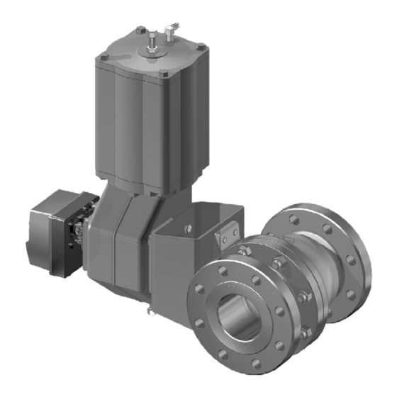
- Page 1 SEAT SUPPORTED FULL BORE BALL VALVE Series XT, XA Installation, Maintenance and Operating Instructions...
-
Page 2: Table Of Contents
Installing the M-type manual gear operator........13 Installing the B1C-series actuator ..13 Installing the B1J-series actuator ..13 Installing other than Metso actuators ... 14 MALFUNCTIONS........... 14 TOOLS ............14 ORDERING SPARE PARTS ......14 READ THESE INSTRUCTIONS FIRST! These instructions provide information about safe handling and operation of the valve. -
Page 3: General
For (1) (2) (5) more information about the type code, see section 12. MADE BY METSO AUTOMATION ATTENTION : READ INSTRUCTIONS BEFORE INSTALLATION OR SERVICING. CONTACT METSO AUTOMATION FOR COPY. BODY SHAFT T max MAX. -
Page 4: Technical Specifications
1 X 70 en Technical specifications T (°F) Face-to-face length:: ASME B.16.10 P (psi) P (bar) Body rating: ASME Class 150, 300 Max pressure differential: see Fig. 5 ASME 300 Temperature range: see Fig. 6 Flow direction: ASME 300 seats S, K, X and T: free H-seat: see Fig. -
Page 5: Safety Precautions
The valve may produce noise in the pipeline. The noise level depends on the application. It can be WRONG measured or calculated using the Metso Nelprof com- puter program. Observe the relevant work environ- ment regulations on noise emission. CAUTION: Fig. -
Page 6: Installation And Use
These cases will normally be associated with large actuators, extended shafts, or where severe vibration is present. Please contact Metso’s Automation business for advice. Commissioning Ensure that there is no dirt or foreign objects left inside the valve or pipeline. -
Page 7: Servicing
1 X 70 en ❑ SERVICING Remove the packing rings (69) from around the shaft using a knife or some other pointed instru- General ment without scratching the surfaces. ❑ Clean the packing ring counterbore. CAUTION: ❑ Place the new packing rings (69) over the shaft Observe the safety precautions mentioned in sec- (5). -
Page 8: Repairing A Jammed Or Stiff Valve Without Removing It From The Pipeline
1 X 70 en Please note that the ball seats can be replaced without detaching the actuator. ❑ Close and detach the actuator pressure supply and disconnect the control cables and pipes. ❑ stud (14) Loosen the bracket screws. disc spring set (150) hexagon nut (18) retaining plate (42) gland (9) -
Page 9: Checking The Parts Of A Dismantled Valve
1 X 70 en Remove the spline driver (2"-8") or thrust ring (1"- 1.5") inside the body. For detailed figures to remove the thrust ring see Fig. 17. Remove the shaft (5) by pulling it outwards. Please note that this will detach the thrust bearings (70) from around the shaft. -
Page 10: Table Of Contents
1 X 70 en ❑ Reassembling the valve Place the back seal (75), back-up ring (76), spring (62) and the seat (25) into body cap, Fig. 20. 4.9.1 Sizes 1" - 8" Body cap Body CAUTION: For safety reasons the retaining plates (42) MUST 1”... - Page 11 1 X 70 en Remove from body cap back seal stack one 0.4 mm thick shim. Repeat the assembly as described earlier. If the torque is still too high remove one 0.4 mm shim from body back seal stack. Continue until appropriate torque is achieved.
-
Page 12: Testing The Valve
1 X 70 en mended torques are given in Table 5. The flange Table 6 Pressing forces for seat locking faces must be in even contact with each other. Valve size Force (kN) Table 5 Recommended tightening torques of the body TA construction stud nuts Recommended tightening torques (Nm) -
Page 13: Installing The Actuator
1 X 70 en INSTALLING THE ACTUATOR tor so that the cylinder is pointing upwards. ❑ Position the actuator parallel or vertical to the General pipeline as accurately as possible. Lubricate the actuator mounting screws and then fasten all CAUTION: screws. -
Page 14: Installing Other Than Metso Actuators
These tools can be ordered from the manufacturer. NOTE: Always give the valve type designation when ordering. Metso accepts no responsibility for compatibility of actu- ators not installed by Metso. ORDERING SPARE PARTS When ordering spare parts, always include the follow-... -
Page 15: Exploded Views And Parts Lists
1 X 70 en EXPLODED VIEWS AND PARTS LISTS 10.1 Sizes 1" - 1 1/2" (type GA) 70, 71 Item Description Spare part category Body Body cap Ball/Q-TRIM ball Spline driver (2" - 8" / DN 50 - 200) Thrust ring (1", 1 1/2" / DN 25, 40) Shaft 1, 2 Ball seat... -
Page 16: Sizes 2" - 8
1 X 70 en 10.2 Sizes 2" - 8" Item Description Spare part category Body Body cap Ball / Q-trim ball Spline driver Shaft Ball seat (S, K and soft seats ) Ball seat (H) Gland Stud Stud Hexagon nut Hexagon nut Ball seat (H) Retaining plate... -
Page 17: Dimensions And Weights
1 X 70 en DIMENSIONS AND WEIGHTS 11.1 Valves 1" - 8" ØO Key acc. to ANSI B17.1 ØB1 ØB DIMENSIONS, mm Weight, kg TYPE Q-XT/ Class ØB ØB1 XT/XA XT_C 4.76 Ø 15 Class 150 1 1/2 4.76 Ø 20 152.4 6.35 Ø... -
Page 18: Valve And B1C/B1J/B1Ja Actuator
1 X 70 en 11.2 Valve and B1C/B1J/B1JA actuator See ØB1 and K dimensions from tables in 11.1 and 11.2 ø B1 * B1C ACTUATOR DIMENSIONS, mm DIMENSIONS, inch TYPE TYPE B1C6 B1C6 15.55 10.63 11.14 1.42 3.54 B1C9 B1C9 17.71 12.40 10.98... -
Page 19: Valve And Hand Lever Lx And Lk
1 X 70 en 11.3 Valve and hand lever LX and LK 11.4 Valve and series M gear operator øB1 HAND LEVER LK MANUAL OPERATOR, SERIES M DIMENSIONS, mm DIMENSIONS, mm Handlever TYPE ØZ LX180 LX220 LK350 10.1 LK350 18.2 LK450 26.2 LK450... -
Page 20: Type Code
316 Stainless steel / (W/Cr)C & XM-19 316 Stainless steel / NiBO & XM-19 Metso Automation Inc. Europe, Levytie 6, P.O. Box 310, 00811 Helsinki, Finland. Tel. +358 20 483 150. Fax +358 20 483 151 North America, 44 Bowditch Drive, P.O. Box 8044, Shrewsbury, MA 01545, USA. Tel. +1 508 852 0200. Fax +1 508 852 8172 Latin America, Av.
Need help?
Do you have a question about the Neles XT Series and is the answer not in the manual?
Questions and answers