
Related Manuals for Metso Neles L4 Series


Summary of Contents for Metso Neles L4 Series
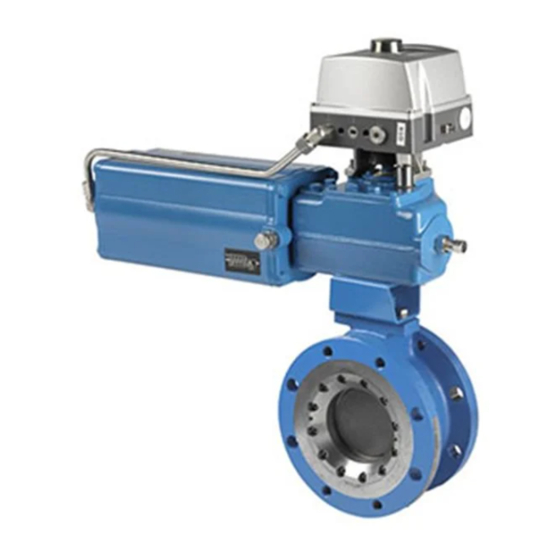
- Page 1 ® NELDISC Metal seated high performance triple eccentric disc valve Series L6, L4 Installation, Maintenance and Operating Instructions...
-
Page 2: Table Of Contents
These instructions provide information about safe handling and operation of the valve. If you require additional assistance, please contact the manufacturer or manufacturer’s representative. Addresses and phone numbers are printed on the back cover. See also www.metso.com/valves for the latest documentation. SAVE THESE INSTRUCTIONS! Subject to change without notice. -
Page 3: General
Fig. 2. Identification plate If you are uncertain about use of the valve or its suitability for your intended purpose, please contact Metso for more Identification plate marking: information. Body material For valves in oxygen service, please see also the separate... -
Page 4: Ce Marking
Beware of noise emissions! The valve may produce noise in the pipeline. The noise level depends on the application. It can be measured or calculated using Metso Nelprof computer software. Observe the relevant work environment regulations on noise emission. CAUTION: Beware of a very cold or hot valve! Fig. -
Page 5: Mounting Into The Pipeline
2 L6 70 en Mounting into the pipeline Flush or blow the pipeline carefully before installing the valve. Foreign particles, such as sand or pieces of welding electrode, will damage the disc sealing surface and seat. The valve may be installed in any position and offers tight- ness in both directions (L6C/D, L6F/D). - Page 6 2 L6 70 en Fig. 8. Stud bolt lenght Table 1. Minimum pipe inside dimensions (mm / in) Table 2. Stud bolt dimensions (mm), L6C ASME Class 150 flanges. Both flanges included. Valve L6F/D L4F/D size Size Thread DN / inch inch inch...
-
Page 7: Actuator
Metso recom- mends inspecting the valves at least every five (5) years. The inspection and maintenance interval depends on the actual Insulation limit application and process condition. -
Page 8: Removing The Valve From The Pipeline
2 L6 70 en NOTE: For safety reasons, replace pressure retaining bolting if the threads are damaged, have been heated, stretched or cor- roded. Removing the valve from the pipeline CAUTION: Do not dismantle the valve or remove it from the pipe- line while the valve is pressurized! It is generally most convenient to detach the actuator and its auxiliary devices (see Section 6), before removing the... -
Page 9: Valve Leakage
2 L6 70 en Table 9. Tightening of gland packing, L6F Spring set dia Compression (h ) mm Thread Packing ring material Graphite PTFE No of studs 31.5 stud (24) 35.5 hexagon nut (25) disc spring set (43) retainer plate (42) packing (20) gland (9) V-ring set or... -
Page 10: Replacing The Seat Ring
2 L6 70 en If the reason for the leakage does not become apparent Centre the seat ring (4) carefully into its groove and after doing the above, the valve must be disassembled for turn the disc to maintain light contact with the seat. ... -
Page 11: Replacing The Disc, Shafts And Bearings
2 L6 70 en Fig. 16. Replacing the seat, L6F Fig. 18. Protecting the disc during disassembly and assembly Replacing the disc, shafts and bearings Assembling the valve Replace damaged parts with new ones. 5.6.1 Disassembling the valve Set the disc and the shaft together beforehand. -
Page 12: Detaching And Installing The Actuator
2 L6 70 en Table 11. Pressing the pins, forces kN Pin diameter, Force, kN Pin diameter, Force, kN 1125 1500 2000 3150 Install the gasket (18) and the blind flange (10). Tighten the screws (26) lightly. Then tighten the screws (26) crosswise and evenly. First to 50 % of recommended torque, then to 100 %. -
Page 13: Installing Ec And Ej Actuators
2 L6 70 en If a bushing is required between the actuator shaft bore and the valve shaft, mount it first in the actua- tor shaft bore. The valve keyway is on the side opposite the flat side of the disc. -
Page 14: Detaching And Installing Other Actuator Types
Tighten the nut of the tool in such a way that the NOTE: tool pulls the drive shaft to the uppermost position. Metso accepts no responsibility for compatibility of actua- The position may be checked from the side of the tors not installed by Metso. - Page 15 2 L6 70 en 6.7.4 Double-acting cylinder actuator B1C Stop screw for the Apply the tabulated shut-off pressure Pc to the air closed position connection at the cylinder base. With the stop screw removed, check through the air connection hole that the piston does not touch the cylinder end.
-
Page 16: Tools
2 L6 70 en 6.7.9 M-series operator TOOLS No special tools are needed for servicing the valve. How- Close the valve as per the tabulated primary torque ever, we recommend an extractor tool (ID-code table in M1 (handwheel torque) given in Tables 14, 15, 16 actuator's IMO) for removing the actuator from the valve. - Page 17 2 L6 70 en Table 14. Series L6C, closing torques...
- Page 18 2 L6 70 en Table 14. Continued...
- Page 19 2 L6 70 en Table 15. Series L6D, closing torques...
- Page 20 2 L6 70 en Table 15. Continued...
- Page 21 2 L6 70 en Table 16. Series L6F/D, L4F/D, closing torques...
- Page 22 2 L6 70 en Table 16. Continued...
- Page 23 2 L6 70 en Table 17. Series L6FB, closing torques...
- Page 24 2 L6 70 en Table 17. Continued...
-
Page 25: Exploded View And Parts List
2 L6 70 en EXPLODED VIEW AND PARTS LIST L6C, L6D Item Description Spare part category Body Clamp ring Disc Seat ring Gland Blind flange Drive shaft Shaft Bearing Bearing Thrust bearing Gasket Body seal 1 set Gland packing Spring washer Anti-extrusion ring Stud Hexagon nut... - Page 26 2 L6 70 en Item Description Spare part category Body Clamp ring Disc Seat ring Casting gland Compression ring Blind flange Drive shaft Shaft Bearing Bearing Gasket Body seal 1 set Gland packing Stud Stud Socket head screw Identification plate Retainer ring Disc spring set * Note: L6F-series sizes 28"...36"...
-
Page 27: Dimensions And Weights
2 L6 70 en DIMENSIONS AND WEIGHTS L6F/D; NPS 4 - 36 L6C; NPS 4 - 32 L6D; NPS 4 - 28 L6C; NPS 36 - 56 , 72, 80 L6D; NPS 32, 36, 40, 56 L6C; NPS 64 L6D; NPS 42, 48 L6C, ASME CLASS 150 Dimensions, mm øB... - Page 28 2 L6 70 en L6D, ASME CLASS 300 Dimensions, mm øB øB1 øH øD øO 157.2 4.76 185.7 22.2 4.76 215.9 269.9 22.2 4.76 269.9 330.2 27.8 6.35 323.8 387.4 39.1 9.52 96.5 450.8 50.4 12.7 110.5 412.8 514.4 55.5 12.7 126.5 469.9...
- Page 29 2 L6 70 en L6F/D, ASME CLASS 600/300 Dimensions, mm øB øB1 øH øD øO 157.2 215.9 4.76 215.9 292.1 22.7 4.76 269.9 349.2 27.8 6.35 323.8 431.8 39.1 9.53 50.4 12.7 412.8 527.0 50.4 12.7 469.9 603.2 55.5 12.7 533.4 654.0 60.6...
- Page 30 2 L6 70 en Y (*) ØD > - " 0 " 4 > - L6F, ASME CLASS 600 Dimensions, mm ØB ØB1 ØH ØD ØO 215.9 292.1 28.5 413.5 362.5 33.45 6.35 157.3 269.9 349.2 39.2 9.525 323.8 431.8 12.7 174.5 56.1...
- Page 31 2 L6 70 en SIZES, NPS 04-08 Only sizes 24" and 28" øB1 øB SIZES, NPS 10-28 L4F/D, ASME CLASS 600/300 Size Dimensions, mm Weight øB øB1 157.2 17.0 4.76 215.9 22.2 4.76 269.9 27.8 6.35 323.8 39.1 9.52 50.4 12.70 412.8 50.4...
- Page 32 2 L6 70 en VALVE + MANUAL GEAR OPERATOR Ø B*) Ø Z SHUT ’) See dimensions K and øB on pages 25 and 28 Type Dimensions, mm Type Dimensions, in 9.40 7.21 2.53 2.03 6.24 9.40 7.21 2.53 2.03 7.80 11.85 9.16...
-
Page 33: Type Code
2 L6 70 en TYPE CODE ® NELDISC HIGH PERFORMANCE TRIPLE ECCENTRIC DISC VALVE Series L6, L4 S-DISC CONSTRUCTION SIZE Flow balancing trim on downstream side of body flow port L6C: 04, 06, 08, 10, 12, 14, 16, 18, 20, 24, 28, 30, 32, 36, 38, 40, 42 48, 52, 54, 56, 60, 64, 72, 80 PRODUCT SERIES / DESIGN L6D: 04, 06, 08, 10, 12, 14, 16, 18, 20, 24, 26, 28, 30, 32, 36, 40,... - Page 34 2 L6 70 en...
- Page 35 2 L6 70 en...
- Page 36 2 L6 70 en Metso Flow Control Inc. Europe, Vanha Porvoontie 229, P.O. Box 304, FI-01301 Vantaa, Finland. Tel. +358 20 483 150. Fax +358 20 483 151 North America, 44 Bowditch Drive, P.O. Box 8044, Shrewsbury, M A 01545, USA. Tel. +1 508 852 0200. Fax +1 508 852 8172 South America, Av.
Need help?
Do you have a question about the Neles L4 Series and is the answer not in the manual?
Questions and answers