
Related Manuals for Metso NELDISC LW Series


Summary of Contents for Metso NELDISC LW Series
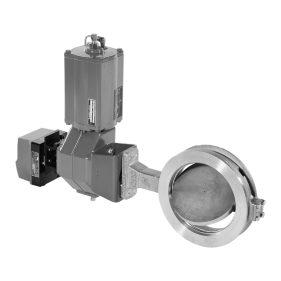
- Page 1 ® NELDISC Metal seated high performance triple eccentric disc valve Series LW, LG Installation, Maintenance and Operating Instructions...
-
Page 2: Table Of Contents
2 LW 70 en Table of Contents GENERAL............3 Scope of the manual ......3 Valve description........3 Valve markings........3 Technical specifications ......4 Valve approvals........4 CE marking ..........4 Recycling and disposal ......4 Safety precautions ......... 4 TRANSPORTATION, RECEPTION AND STORAGE.......... -
Page 3: General
Identification plate marking: If you are uncertain about the use of the valve or its Body material suitability for your intended use, please contact Shaft material Metso’s Automation business for more information. Trim material Seat material Valve description Maximum operating temperature... -
Page 4: Technical Specifications
It can be Most parts have material marking. A material list is sup- measured or calculated using Metso Nelprof software. plied with the valve. In addition, separate recycling and Observe the relevant work environment regulations on disposal instructions are available from the manufac- noise emission. -
Page 5: Transportation, Reception And Storage
2 LW 70 en TRANSPORTATION, RECEPTION AND STORAGE The recommended position of the Check the valve and the accompanying devices for any perforated plate damage that may have occurred during transport. is at the "top" of the Store the valve carefully before installation, preferably pipeline indoors in a dry place. - Page 6 2 LW 70 en Table 1. Minimum pipe inside dimensions (mm) Valve size LW6L, LW7L, LW8M, LG8M, DN / NPS LG6L, LG7L LW5M, LG5M (mm / inch) (mm / inch) 80 / 3 69 / 2.71 69 / 2.72 100 / 4 90 / 3.54 90 / 3.54 125 / 5...
- Page 7 2 LW 70 en Table 2. continued LG6L DIN PN 10 flange DIN PN 16 flange DIN PN 25 flange DIN PN 20 flange Thread Thread Thread Thread LG7L DIN PN 10 flange DIN PN 16 flange DIN PN 25 flange DIN PN 20 flange Thread Thread...
-
Page 8: Actuator
❑ gasket thickness of 1.5 mm actuator is recommended. ❑ heavy nuts with washers ❑ Please contact Metso’s Automation business for further flange thickness of weldneck flanges per DIN or information. COMMISSIONING 3.2.1 Valve insulation Ensure that no dirt or foreign objects are left inside the If necessary, the valve may be insulated. -
Page 9: Service
2 LW 70 en ❑ SERVICE Unfasten the nuts (25) and remove the disc spring (TA-Luft) sets (43), the retaining plates (42) and CAUTION: the gland (9). Observe the safety precautions listed in Section ❑ Remove old packing rings (20). Do not damage the 1.8 before starting work! surfaces of the packing ring counterbore and shaft. -
Page 10: Valve Leakage
2 LW 70 en ❑ Ensure that the valve is not pressurized. ❑ Remove the valve from the pipeline. The valve must be in a closed position during removal. Follow the lifting methods shown in Section 3. ❑ Remove the clamp ring (2) by untightening the screws (27). -
Page 11: Replacing The Disc, Shafts And Bearings
2 LW 70 en Replacing the disc, shafts and bearings removal of the old pins the holes can be drilled to a larger pin size. File off any burrs from the shafts. 5.6.1 Disassembling the valve The bearing material of the standard construction valves is PTFE-impregnated stainless steel net. -
Page 12: Detaching And Installing The Actuator
2 LW 70 en (see Fig. 18). Use a smaller tool than the pin stroke limit stop screws are adjusted in advance. diameter. See Table 7 for forces. Detaching the B1 series actuators ❑ Disconnect the actuator from its power source; detach the air supply pipe and control signal cables or pipes from their connectors. -
Page 13: Installing Ec And Ej Actuators
2 LW 70 en Table 8. Bushing dimensions according to Fig. 23. Insert cylindrical pins (III) in the bushing slots, these must be directed into the Outer dim. Inner dim. Height Actuator corresponding slots in the actuator during tight- (mm) (mm) (mm) ening. -
Page 14: Detaching And Installing Other Actuator Types
NOTE: against the upper surface of the housing. Metso accepts no responsibility for compatibility of actu- ❑ Install the actuator on the valve and attach the ators not installed by Metso. - Page 15 2 LW 70 en 6.7.4 Double-acting cylinder actuator B1C Stop screw for the closed position ❑ Apply the tabulated shut-off pressure Pc to the air connection at the cylinder base. ❑ With the stop screw removed, check through the air connection hole that the piston does not touch the cylinder end.
-
Page 16: Tools
2 LW 70 en 6.7.10 Hand lever RH ❑ Mount the hand lever on the valve, but do not fas- ten hex screws (A). Turn the lever using force F in Table 10. ❑ When closing torque is applied, turn the housing (B) cog of the closing limit to contact with the lever arm. - Page 17 2 LW 70 en Table 11. Series LW6L, LW7L, LG6L and LG7L, closing torques...
- Page 18 2 LW 70 en Table 12. Series LW8M, LG8M, LW5M and LG5M, closing torques...
-
Page 19: Exploded View And Parts List
2 LW 70 en EXPLODED VIEW AND PARTS LIST Item Description Spare part category Body Clamp ring Disc Seat ring Gland Blind flange Drive shaft Shaft Bearing Bearing Gasket Body seal 1 set Gland packing Anti-extrusion ring Stud Hexagon nut Hexagon screw Hexagon socket screw Identification plate... -
Page 20: Dimensions And Weights
2 LW 70 en DIMENSIONS AND WEIGHTS DN 80 - 125 DN 350 - 400 DN 150 - 400 øB LW6LB, LW7LB, key connection Dimensions, mm Dimensions, mm Weight Thread Thread LW6L LW7L A (K1) A (K2) 4.76 17.0 4.76 22.2 4.76 22.2... - Page 21 2 LW 70 en DN 80 - 125 FLANGE DRILLINGS DN 150 - 400 LG6LB, LG7LB, key connection Dimensions, mm Flange drillings Dimensions, mm Thread Thread LG6L LG7L PN 10 PN 16 PN 25 ISO PN 20 A (K1) A (K2) Thread Qty Thread Qty Thread Qty Thread Qty 205 120 168 248 70 105 4.76 25 17.0...
- Page 22 2 LW 70 en MOUNTING POSITION B (STANDARD) øZ LW6LB, LW7LB + M series Valve Actuator Dimensions, mm LW_LM LG_LM ISO 5211 A A (K1) A (K2) F2 (* G2 (* M07/F07 M07/F07 M07/F07 LW6L / M07/F07 LG6L M10/F10 or M10E/F10 LW7L / M12/F12 or M12E/F12 LG7L...
- Page 23 2 LW 70 en MOUNTING POSITION B (STANDARD) 1/4 NPT LW6LB, LW7LB + B1C Valve Actuator Dimensions, mm LW_L- LG_L- A (K1) A (K2) B1C9 B1C9 B1C11 B1C9 B1C11 B1C9 B1C11 B1C13 B1C11 LW6L / B1C13 LG6L B1C17 LW7L / B1C13 LG7L B1C17...
- Page 24 2 LW 70 en MOUNTING POSITION B (STANDARD) LW6LB, LW7LB + B1J Valve Actuator Dimensions, mm LW_L- LG_L- A (K1) A (K2) B1J8 B1J8 B1J10 B1J8 B1J10 B1J8 B1J10 B1J12 B1J10 LW6L / B1J12 LG 6L B1J16 LW7L / B1J12 LG7L B1J16 B1J12...
- Page 25 2 LW 70 en MOUNTING POSITION D-HL (STANDARD) Syöttö G1/4" VDI/VDE 3845 LW6LB, LW7LB + EC Valve Actuator Dimensions, mm VDI/ LW_L- LG_L- A (K1) A (K2) 3845 EC07 G1/4 EC10 G1/4 EC10 G1/4 EC12 G1/4 LW6L / LG6L EC10 G1/4 EC12 G1/4...
- Page 26 2 LW 70 en MOUNTING POSITION D-HL (STANDARD) Supply G1/4" VDI/VDE 3845 Model EJ_A spring to open Model EJ_ spring to close LW6LB, LW7LB + EJ Valve Actuator Dimensions, mm VDI/ LW_L- LG_L- A (K1) A (K2) 3845 EJ07 G1/4 EJ10 G1/4 LW6L /...
-
Page 27: Flange Drilling And Compatibility
2 LW 70 en 10.1 Flange drilling and compatibility LW6L, 7L DIN PN 10 DIN PN 16 DIN PN 25 DIN PN 40 ISO PN 20 ISO PN 50 ASME 150 ASME 300 JIS 10K JIS 16K JIS 20K JIS 30K DN 080 DN 100 DN 125... -
Page 28: Type Code
1.4581 (Nitronic 50) Metso Automation Inc. Europe, Vanha Porvoontie 229, P.O. Box 304, FI-01301 Vantaa, Finland. Tel. +358 20 483 150. Fax +358 20 483 151 North America, 44 Bowditch Drive, P.O. Box 8044, Shrewsbury, MA 01545, USA. Tel. +1 508 852 0200. Fax +1 508 852 8172 South America, Av.
Need help?
Do you have a question about the NELDISC LW Series and is the answer not in the manual?
Questions and answers