Table of Contents
Advertisement
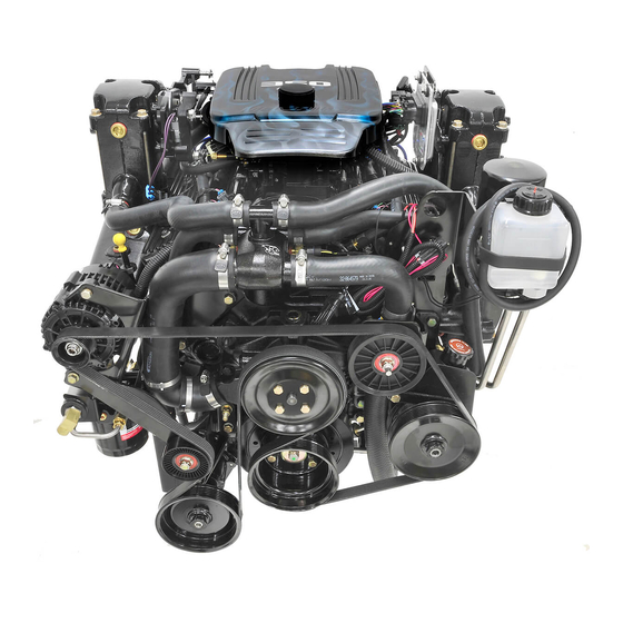
GASOLINE ENGINE TOW SPORTS AND
INBOARD MODELS INSTALLATION MANUAL
Models Covered
Inboard
350 MAG MPI
MX 6.2 MPI
Tow Sports
350 MAG MPI
Horizon
350 MAG MPI Horizon
MX 6.2 MPI Horizon
Notice
After completing installation, these instructions should be placed with the
product for the owner's future use.
Predelivery preparation instructions must be performed before delivering boat
to the product owner.
Page 1 of 77
Model
Model
Model
Printed in U.S.A. - 2002, Mercury Marine
The following are registered trademarks of
Brunswick Corporation: Merc, MerCathode,
Mercury MerCruiser, Mercury, Mercury
Marine, Quicksilver, RideGuide, Thruster
and Mercury Precision Parts.
Serial Number or Year
0M310000 and Above
Serial Number or Year
0M310000 and Above
Serial Number or Year
0M310000 and Above
NOTICE
NOTICE
90-864198020 MARCH 2002
INDEX
Advertisement
Table of Contents

Related Manuals for Mercury MX 6.2 MPI


Summary of Contents for Mercury MX 6.2 MPI
- Page 1 After completing installation, these instructions should be placed with the product for the owner’s future use. NOTICE Predelivery preparation instructions must be performed before delivering boat to the product owner. Printed in U.S.A. - 2002, Mercury Marine Page 1 of 77 90-864198020 MARCH 2002...
-
Page 2: Table Of Contents
INDEX INSTALLATION MANUAL Table Of Contents General Information ..... . Exhaust System ......Notice to Boat Manufacturer/Installer . -
Page 3: General Information
NOTE: Refer to the Mercury MerCruiser Product Applications Manual - Gasoline Inboard Models for application recommendations. This installation manual has been written and published by Mercury Marine to aid the boat manufacturer (OEM) in the installation of the products described herein. -
Page 4: Torque Specifications
INDEX INSTALLATION MANUAL Torque Specifications NOTE: Securely tighten all fasteners not listed below. Description lb-in. lb-ft Engine Mount Bracket Screws Trunnion Clamping Bolt and Nut Propeller Shaft Nut Exhaust Manifold Screw Coupler Bolts Refer to Fuel Delivery System. Lubricants / Sealants / Adhesives Description Where Used Part Number... -
Page 5: Quicksilver Products
Quicksilver gauges, remote controls, steering systems, propellers and other accessories are available for this product. Mercury MerCruiser recommends the use of Quicksilver parts on all applications. Refer to Mercury Precision Parts / Quicksilver Accessories Guide for a complete listing. This Guide is available from:... -
Page 6: Transmissions
INDEX INSTALLATION MANUAL Transmissions Velvet Drive Transmissions On the Velvet Drive 71C and 72C In-Line and 72C Remote V-Drive Transmissions the gear ratio (in FORWARD gear) is marked on transmission identification plate. Transmission out- put shaft rotation and propeller rotation required (in FORWARD gear) are indicated on a de- cal on the transmission case. -
Page 7: Zf / Hurth Transmissions
INDEX INSTALLATION MANUAL ZF / Hurth Transmissions On the ZF / Hurth 630A 8 Degree Down-Angle and 630V V-Drive Transmissions the transmission identification plate indicates gear ratio, serial number and model. 73587 Typical ZF / Hurth Down-Angle Transmission Shown (V-Drive Similar) Transmission Identification Plate 90-864198020 Page 7 of 77... -
Page 8: Propeller Rotation
INDEX INSTALLATION MANUAL Propeller Rotation Propeller rotation is not necessarily the same as engine rotation. Refer to the appropriate following information and drawings for specific information. These transmissions are full power reversing transmissions, allowing a standard (LH rotation) engine to be used for both propeller rotations. Propeller rotation (output shaft rotation) is determined by shift cable attachment at the remote control. - Page 9 INDEX INSTALLATION MANUAL 25506 ZF / Hurth 630A or 800A - 8 Degree Down-Angle Transmissions 72959 ZF / Hurth 630V - V-Drive Transmissions Direction Of Shift Lever Engagement (Toward Flywheel) Engine/Transmission Input Shaft Rotation Direction (LH) Transmission Output/Propeller Shaft Rotation Direction (LH) Direction Of Shift Lever Engagement (Away From Flywheel) Transmission Output/Propeller Shaft Rotation Direction (RH) 90-864198020...
-
Page 10: Boat Construction
INDEX INSTALLATION MANUAL DUAL INSTALLATIONS Best all-around performance usually is obtained by installing engines so that propellers turn outboard (looking at the stern). 22457 Outboard Propeller Rotation RH Rotation LH Rotation VELVET DRIVE IN-LINE AND V-DRIVE TRANSMISSIONS (EXCEPT 5000 SERIES) IMPORTANT: Velvet Drive In-Line and V-Drive Transmissions Only –... -
Page 11: Seawater Connections
INDEX INSTALLATION MANUAL Seawater Connections - General Information NOTICE Refer to manufacturer’s instructions for information on removal and installation of other than Quicksilver Seawater Pickups. IMPORTANT: Seal the inside edges of any hole made through the hull with a suitable sealant to prevent water absorption and deterioration. - Page 12 INDEX INSTALLATION MANUAL TRANSOM MOUNTED 1. Seal the inside edges of the 1-1/2 in. (38 mm) hole hose fitting. 2. Ensure that the hose fitting and plastic plug are in place and threads have been sealed prior to tightening each securely. NOTE: Use a sharp knife or wood chisel to remove excess plastic plug material so that plug is flush with pickup casting.
- Page 13 INDEX INSTALLATION MANUAL NOTE: Some installations may have 7/32 in. (5 mm) holes drilled in transom using four 5/16 in. diameter stainless steel lag bolts in place of round head screws. In any case, flat washers and O-rings are required as outlined. 72641 Water Pickup Installed on Transom Diagonal Mount - Leading Edge Of Pickup 1/8 in.
-
Page 14: Preliminary Connections
INDEX INSTALLATION MANUAL Preliminary Connections Fuel Inlet Fitting IMPORTANT: The following information is provided to ensure proper installation of brass fittings or plugs installed into fuel pump or fuel filter base: • Use #592 Loctite Pipe Sealant with Teflon on threads of fuel inlet fittings or plugs. DO NOT USE TEFLON TAPE. -
Page 15: Inline Fuel Filter
INDEX INSTALLATION MANUAL Inline Fuel Filter INSTALLATION IMPORTANT: If the engine is equipped with a boost pump, an inline filter must be installed between the fuel tank and the boost pump. WARNING Avoid injury or death and power package damage from an electrical shock, fire or explosion. - Page 16 INDEX INSTALLATION MANUAL 9. Install and torque screw and washer through the mounting clip into the stringer. Description lb-in. lb-ft Screw, Mounting Clip 12.2 10. Install and torque hose clamps over hose and insert barbs into hose. 78289 Fuel Line Stringer Clips Fuel Line Description lb-in.
-
Page 17: Coolant Recovery System Connections
INDEX INSTALLATION MANUAL Coolant Recovery System Connections 1. Select a mounting location for coolant recovery bottle and mounting bracket that meets all of the following: • Within limits of clear plastic tubing. • Level with or above the heat exchanger fill neck. •... -
Page 18: Engine Mount Pre-Adjustment
INDEX INSTALLATION MANUAL Engine Mount Pre-Adjustment 1. Remove hardware holding engine to shipping pallet. Attach a suitable sling to lifting eyes on engine. Lift engine from pallet with an overhead hoist. 2. Remove L-shaped shipping bracket from both rear (transmission) mounts as shown. Retorque mount bracket attaching screw to 47 lb-ft (64 Nm). -
Page 19: Engine Preparation
INDEX INSTALLATION MANUAL Engine Preparation 1. Remove and read all tags attached to engine. 2. Remove all hardware that secures engine to shipping container. 3. Connect battery cables to engine. Be sure to observe the following: a. Ensure that grounding stud and starter solenoid terminal are free of paint or any oth- er material that could cause a poor electrical connection. -
Page 20: Engine Installation And Initial Engine Alignment
INDEX INSTALLATION MANUAL Engine Installation and Initial Engine Alignment Models With 8 Degree Down Angle Transmissions - Velvet Drive or ZF / Hurth 1. Remove the engine cover. 2. Attach a suitable sling to lifting eyes on engine and adjust so that engine is level when suspended. - Page 21 INDEX INSTALLATION MANUAL 4. Position engine on engine bed so that transmission output flange and propeller shaft coupler are visibly aligned (no gap can be seen between coupling faces when butted together). Adjust engine height if necessary to obtain proper alignment. DO NOT use mount adjustments to adjust engine position at this time.
-
Page 22: Models With V-Drive Transmissions
INDEX INSTALLATION MANUAL Models with V-Drive Transmissions 1. Lift engine into position in boat using an overhead hoist. 2. Install quick drain oil hose plug in oil drain hose. 3. Position engine so that enough propeller shaft protrudes through transmission and out- put flange for propeller shaft coupler to be attached. -
Page 23: All Models
INDEX INSTALLATION MANUAL All Models 1. Push end of oil drain hose out of boat hull through flange. 2. Pull oil drain hose out until it is 6 in. (152 mm) from the propeller. 3. Move alignment clip on the oil drain hose and squeeze to position it on the hose just in- side of the boat hull against the flange. -
Page 24: Hot Water Heater Installation
INDEX INSTALLATION MANUAL Hot Water Heater Installation IMPORTANT: When connecting a cabin heater or hot water heater: • Supply hose (from engine to heater) and return hose (from heater to engine) MUST NOT EXCEED 5/8 in. (16 mm) I.D. • Make heater connections ONLY at locations shown. •... - Page 25 INDEX INSTALLATION MANUAL 77933 All Models Location for Hot Water Supply RETURN HOSE CONNECTION 77954 Location For Hot Water Return 90-864198020 Page 25 of 77...
-
Page 26: Exhaust System
INDEX INSTALLATION MANUAL Exhaust System CAUTION It is the responsibility of the boat manufacturer or installing dealer to properly lo- cate the engine and install the exhaust system. Improper installation may allow wa- ter to enter the exhaust manifolds and combustion chambers and severely damage the engine. - Page 27 INDEX INSTALLATION MANUAL 5. Move load weight to bow to simulate greatest bow-down attitude the boat will encounter in normal operation. 6. Recheck exhaust system slope. 7. Move load weight and cargo weight to stern of boat to stimulate greatest stern-down attitude the boat will encounter such as when loading.
- Page 28 INDEX INSTALLATION MANUAL 9. If measurements are less than specified, exhaust elbow risers must be installed to achieve proper dimension. Ê Ê Ê 78489 No Riser 3 Inch Riser 6 Inch Riser Exhaust Manifold Restrictor Gasket Exhaust Elbow 3 Inch Riser 6 Inch Riser Open Gasket Plug...
-
Page 29: Measurement Methods
3. With the straight edge above the engine and parallel to the water measure the distance between the straight edge and the outside waterline. 4. The difference between these two measurements is the exhaust elbow height above the water line. Refer to Measuring Procedure and compare measurement to Mercury MerCruiser’s specifications. 76859... - Page 30 Inboard 350 MAG MPI / 350 MAG MPI Horizon 4 in. (102 mm) 3 in. (76 mm) MX 6.2L MPI / MX 6.2 MPI Horizon Tow Sports 350 MAG MPI 3 1/2 (88.9 mm) Not Applicable Page 30 of 77...
- Page 31 INSTALLATION MANUAL NOTE: A kit is available to reduce from the 4 in. (102 mm) to 3 in. (76 mm). Refer to the Mercury Precision Parts / Quicksilver Accessories Guide, for kit part number. 71774 Typical Continuously Sloping Exhaust Line...
-
Page 32: Exhaust System Hose / Tube Connections
INDEX INSTALLATION MANUAL Exhaust System Hose / Tube Connections CAUTION Avoid exhaust hose failure. Discharge water from exhaust elbow must flow around entire inside diameter of hose to avoid causing hot spots which could eventually result in burned-through exhaust hoses. Exhaust hoses and/or tubes must be cor- rectly connected to exhaust elbows so that they do not restrict the flow of discharge water from exhaust elbow. -
Page 33: Electrical Connections
We recommend the use of Quicksilver Instrumentation and Wiring Harnesses. On dual sta- tion applications, oil pressure and water temperature senders (on engine) must be changed. Refer to Mercury Precision Parts / Quicksilver Accessories Guide for selection. The 4 basic gauges that must be used with the engine are: •... -
Page 34: Audio Warning System Connections
INDEX INSTALLATION MANUAL 4. Connect the instrumentation wiring harness to engine harness plug at location shown. 78030 Engine Harness Plug 5. Tighten hose clamp to secure wiring harness to engine harness plug. Audio Warning System Connections WARNING Alarm is not external ignition-proof, therefore, DO NOT mount alarm in engine or fuel tank compartments. -
Page 35: Fluid Connections
INDEX INSTALLATION MANUAL 6. Place the large decal on the instrument panel or other appropriate location in easily viewed by the operator. ALARM INDICATES LOW OIL OR OVERHEATING APPLY THE PROPER DECAL TO THE DASHBOARD OR OTHER APPROPRIATE LOCATION: AUDIO WARNING HORN WILL SOUND WHEN: 1. -
Page 36: Final Engine Alignment
INDEX INSTALLATION MANUAL Final Engine Alignment IMPORTANT: Engine alignment MUST BE RECHECKED with boat in the water, fuel tanks filled and with a normal load on board. Engine must be aligned so that transmission and propeller shaft coupling centerlines are aligned and coupling faces are parallel within .003 in. - Page 37 INDEX INSTALLATION MANUAL NOTE: Some propeller shaft couplers may not have a shoulder on mating face. On these installations, use a straight edge to check centerline alignment. 74483 Transmission Output Flange Propeller Shaft Coupler Propeller Shaft Straight Edge 4. Check for angular misalignment by hand holding coupling faces tightly together and checking for a gap between coupling faces with a .003 in.
- Page 38 INDEX INSTALLATION MANUAL 5. If coupling centerlines are not aligned or if coupling faces are more than .003 in. (0.07 mm) out of parallel, adjust engine mounts. a. TO ADJUST ENGINE UP OR DOWN: Loosen locking nut on mounts requiring adjustment and turn adjusting nuts in desired direction to raise or lower.
- Page 39 INDEX INSTALLATION MANUAL 10. Secure coupling together with bolts, lockwashers and nuts. Torque fasteners. 75535 Bolts Transmission Coupler Description lb-ft lb-in. Coupling Bolts And Nuts a. If propeller shaft coupler has set screws, remove set screws and mark dimple loca- tions using a transfer punch.
-
Page 40: Throttle Cable Installation And Adjustment
Damage caused to transmission as a result of improper shift lever positioning will not be covered by warranty. To ensure proper shift and throttle operation, we recommend the use of a Quicksilver remote control and cables. Refer to Mercury Precision Parts / Quicksilver Accessories Guide. Shift Cable Travel 2-3/4 in. (70 mm) -
Page 41: Velvet Drive Transmissions
INDEX INSTALLATION MANUAL Velvet Drive Transmissions IN-LINE AND REMOTE V-DRIVE IMPORTANT: Velvet Drive Transmission Warranty is jeopardized if the shift lever pop- pet ball or spring is permanently removed, if the shift lever is repositioned or changed in any manner or if remote control and cable do not position shift lever correctly. –... - Page 42 INDEX INSTALLATION MANUAL 2. Place remote control shift lever and transmission shift lever in NEUTRAL position. 3. Remove nuts and washers from shift cable attaching studs. 4. Locate center of remote control and control shift cable play (backlash), as follows: a.
- Page 43 INDEX INSTALLATION MANUAL 11. Reattach nut and washer to cable barrel stud. Tighten until they contact. Tighten securely, but DO NOT overtighten. 50947 Rear Entry Single Station Installation In-Line And Remote V-Drive 50947 Rear Entry Dual Station Installation In-Line And V-Drive Cable End Guide Cable Barrel Cable Barrel Stud...
- Page 44 INDEX INSTALLATION MANUAL 50946 Front Entry Single Station Installation In-Line And V-Drive 50946 Front Entry Dual Station Installation In-Line And V-Drive Cable End Guide Cable Barrel Cable Barrel Stud Elastic Stop Nut and Washer Spacer Cable End Guide Stud Elastic Stop Nut and Washer NOTE: For models equipped with a dual station shift bracket such as the one shown, refer to shift cable manufacturer’s instructions for adjusting the cable.
- Page 45 INDEX INSTALLATION MANUAL 5000 SERIES (8 DEGREE DOWN ANGLE AND V-DRIVE) For Left-Hand Propeller Shaft Rotation: Shift cable hookup at remote control must result in shift cable end guide moving in direction “A” when remote control handle is placed in FORWARD position.
- Page 46 INDEX INSTALLATION MANUAL WARNING Avoid serious injury or property damage caused by improper shifting. Anchor stud for shift cable must be installed in the correct hole. 1. Be certain anchor stud is installed in the front hole as shown in the illustration following. 73284 Shift Cable Bracket Anchor Stud In Front Hole...
- Page 47 INDEX INSTALLATION MANUAL IMPORTANT: Velvet Drive Transmission Warranty is jeopardized if the shift lever pop- pet ball or spring is permanently removed, if the shift lever is repositioned or changed in any manner or if remote control and shift cable do not position shift lever exactly as shown.
- Page 48 INDEX INSTALLATION MANUAL 71972 71780 Typical Single Cable Installation - Rear Entry Cable End Guide Spacer (As Required) Elastic Stop Nut and Washer Bushings Cable Barrel Location Cable Barrel Stud Cable End Guide Stud 71897 50073 Typical Dual Cable Installation - Rear Entry Cable End Guide Spacer (As Required) Elastic Stop Nut and Washer...
-
Page 49: Zf / Hurth Transmissions
INDEX INSTALLATION MANUAL ZF / Hurth Transmissions IMPORTANT: These ZF / Hurth transmissions are full reversing transmissions. Direc- tion of output/propeller rotation is determined by hookup of shift cable at remote con- trol. Shift cable must be hooked up to remote control before starting installation and adjustment procedures. - Page 50 INDEX INSTALLATION MANUAL 2. Check shift lever positioning as indicated: IMPORTANT: Check that shift lever is positioned approximately 10 degrees aft of vertical when in the NEUTRAL detent position and that the distance “c” between studs in the following is set at 7-1/8 in. (181 mm). If necessary, loosen clamping bolt and position lever so that dimension “c”...
- Page 51 INDEX INSTALLATION MANUAL 7. Temporarily install shift cable. Do not secure at this time. 73587 Typical Shift Cable End Guide IMPORTANT: Transmission is fully in gear when shift lever comes to a stop in either direction. 8. Place remote control shift lever in FORWARD gear position. Ensure that transmission is fully in gear, as follows: a.
- Page 52 INDEX INSTALLATION MANUAL 11. Reattach locknut and washer to cable end guide stud. Tighten until they contact, then loosen 1/2 turn. 12. Reattach locknut and washer to cable barrel stud. Tighten until they contact. Tighten securely, but DO NOT overtighten. NOTE: To change cable approach direction on single or dual station installations, only the spacers/bushings have to be switched to the opposite stud (the studs are identical).
- Page 53 INDEX INSTALLATION MANUAL 73590 71211 Typical Dual Cable - Forward Entry Cable End Guides Locknut and Washer Spacer (Fits over Stud) Bushings Cable Barrel Locations Cable Barrel Stud Cable End Guide Stud 73591 50073 Typical Dual Cable - Rear Entry Cable End Guides Locknut and Washer Spacer (Fits over Stud)
-
Page 54: Predelivery Preparation
Because of the many variables of boat design, only testing will determine the best propeller for a particular application. Available propellers are listed in the Mercury Precision Parts / Quicksilver Accessories Guide. See BOAT IN THE WATER TESTS, Maximum RPM Test at the back of this manual. -
Page 55: Fuel Line Connection
INDEX INSTALLATION MANUAL ENGINE REV-LIMITER IMPORTANT: The engines listed in the following chart are equipped with a rpm rev- limiter that is set to an upper (or limited) rpm amount. This limit is slightly above the normal operating range of the engine and is designed to help prevent damage from excessive engine rpm. - Page 56 INDEX INSTALLATION MANUAL BATTERY CABLES 1. Select proper size positive (+) and negative (–) battery cables, using chart. Battery should be located as close to engine as possible. IMPORTANT: Terminals must be soldered to cable ends to ensure good electrical contact.
-
Page 57: Test Running Engine
Do not leave helm unattended when making test with boat in the water. 1. Ensure that cooling system drain plugs, petcocks and hoses are installed and tight. NOTE: Refer to appropriate Mercury MerCruiser Operation, Maintenance and Warranty Manual for operating specifications. Refer to appropriate Mercury MerCruiser Service Manual for fluid capacity information. -
Page 58: Boat In The Water Tests
ENGINE IDLE SPEED ADJUSTMENT Engine should idle at rpm (as specified in appropriate Mercury MerCruiser Operation, Main- tenance and Warranty Manual) with boat in the water, drive unit in FORWARD gear and en- gine at normal operating temperature. -
Page 59: Cold Weather And Extended Storage
INSTALLATION MANUAL Cold Weather and Extended Storage IMPORTANT: Mercury MerCruiser recommends that propylene glycol antifreeze (a nontoxic and environmentally safe) antifreeze be used in the seawater section of the cooling system for cold weather or extended storage. Ensure that the propylene gly- col antifreeze contains a rust inhibitor and is recommended for use in marine en- gines. -
Page 60: Identification
INDEX INSTALLATION MANUAL Identification AIR ACTUATED SINGLE POINT DRAIN SYSTEM 77955 77955 Closed Cooled Models Seawater Cooled Models Blue Drain Plug Location Blue Air Pump Air Manifold Green Indicators 3 POINT MANUAL DRAIN SYSTEM 77908 77917 Blue Drain Plug Page 60 of 77 90-864198020... -
Page 61: Boat In Water
INDEX INSTALLATION MANUAL Boat In Water AIR ACTUATED SINGLE POINT DRAIN SYSTEM NOTE: This procedure is written for the air pump that is attached to the engine. However, any air source can be used. 1. Close the seacock. 2. Remove the blue air pump from the engine. 3. - Page 62 12. Remove the air pump from the air manifold and return it to the mounting bracket. 13. Mercury MerCruiser recommends leaving the drain system open while transporting the boat or while performing other maintenance. This helps ensure that all water is drained.
- Page 63 INDEX INSTALLATION MANUAL 3 POINT MANUAL DRAIN SYSTEM NOTE: Use this procedure if your engine is not equipped with an air actuated single point drain system or if the single point drain system fails. 1. Close the seacock. 2. Remove the blue drain plug from the distribution housing (lower front, port side). 77917 Blue Drain Plug 3.
- Page 64 4. Remove the two blue drain plugs from the seawater pickup pump (front, starboard side). 77908 5. Verify that water is draining from each opening. 6. Allow the system to drain for a minimum of 5 minutes. Mercury MerCruiser recommends leaving the drain system open while transporting the boat or while performing other maintenance.
-
Page 65: Boat Out Of The Water
INDEX INSTALLATION MANUAL Boat Out Of The Water AIR ACTUATED SINGLE POINT DRAIN SYSTEM NOTE: This procedure is written for the air pump that is attached to the engine. However, any air source can be used. 1. Remove the blue air pump from the engine. 2. - Page 66 9. Remove the air pump from the air manifold and return it to the mounting bracket. 10. Mercury MerCruiser recommends leaving the plugs out while transporting the boat or while performing other maintenance to ensure that all water is drained.
-
Page 67: All Models
Blue Drain Plug 2. Verify that water is draining from each opening. 3. Allow the system to drain for a minimum of 5 minutes. Mercury MerCruiser recommends leaving the plugs out while transporting the boat or while performing other maintenance to ensure that all water is drained. -
Page 68: Instrumentation
INDEX INSTALLATION MANUAL Instrumentation Single Station Installations - Typical BLK = BLACK BLU = BLUE BRN = BROWN GRY = GRAY GRN = GREEN ORN = ORANGE PNK = PINK PUR = PURPLE RED = RED TAN = TAN WHT = WHITE YEL = YELLOW LIT = LIGHT DRK = DARK... - Page 69 INDEX INSTALLATION MANUAL Refer to gauge manufacturer’s instructions for specific connections. NOTE: Connect Wires Together with Screw and Hex Nut; Apply Liquid Neoprene to Con- nection and Slide Rubber Sleeve over Connection. NOTE: Power for a Fused Accessory Panel May Be Taken from This Connection. Load Must Not Exceed 40 Amps.
-
Page 70: Ecm 555 Efi System Engine Wiring Diagrams
INDEX INSTALLATION MANUAL ECM 555 EFI System Engine Wiring Diagrams Typical Starting System RED/PUR YEL/RED RED/PUR RED/PUR YEL/RED 72930 Ignition Switch 20 Amp Fuse Starter Slave Solenoid Circuit Breaker Starter Motor Wire Junction Neutral Safety Switch 90 Amp Fuse Engine Ground (–) Page 70 of 77 90-864198020... - Page 71 INDEX INSTALLATION MANUAL Typical Starting System (continued) This is a general description of the positive current flow from the battery through the starting system until the starter motor cranks. NOTE: Ensure that all connections are tight and have the required resistance. •...
- Page 72 INDEX INSTALLATION MANUAL Wake, Horn and Tachometer Circuits GRY/WHT DK BLU YEL/RED ORN/LT BLU RED/PPL SPLICE 102 SPLICE 113 10 11 12 13 14 15 16 10 11 12 13 14 15 16 17 18 19 20 21 22 23 24 17 18 19 20 21 22 23 24 GRY/WHT Analog Coolant Sender...
- Page 73 INDEX INSTALLATION MANUAL CAN, Fuel Level, Paddle Wheel and Temperature Circuit SPLICE 100 BLK/PNK LT BLU/BLK 10 11 12 13 14 15 16 10 11 12 13 14 15 16 17 18 19 20 21 22 23 24 17 18 19 20 21 22 23 24 SPLICE 104 SPLICE 102 ECM 555...
-
Page 74: Water Flow Diagrams
INDEX INSTALLATION MANUAL Water Flow Diagrams NOTE: Certain components in the following diagram may look different than on your particu- lar power package, but the water flow paths remain similar on all engines. Closed Cooled Models 77928 Exhaust Elbow Exhaust Manifold Seawater Pump Heat Exchanger (Closed Cooled Models Only) Water Circulating Pump... - Page 75 INDEX INSTALLATION MANUAL Seawater Cooled Models 78491 Exhaust Elbow Exhaust Manifold Seawater Pump (Not On Alpha Seawater Cooled Models) Heat Exchanger (Closed Cooled Models Only) Water Circulating Pump Thermostat Housing Water Distribution Housing Cool Fuel Box Check Valve Transmission Cooler Flush Fitting (Inboard Models) Flush Connection (Inboard Models) Shaft Log Seal Connection Point...
- Page 76 INDEX INSTALLATION MANUAL THIS PAGE IS INTENTIONALLY BLANK Page 76 of 77 90-864198020...
-
Page 77: Predelivery Inspection
INDEX INSTALLATION MANUAL Predelivery Inspection Check/ Check/ Applicable Adjust Applicable Adjust CHECK BEFORE RUNNING ON THE WATER TEST Drain plug in and petcocks Engine alignment (Inboards only) closed Seawater inlet valve open Starter neutral safety switch operation Engine mounts tight Water pump operation Engine alignment Instruments(s) operation...
Need help?
Do you have a question about the MX 6.2 MPI and is the answer not in the manual?
Questions and answers