Table of Contents
Advertisement
Quick Links
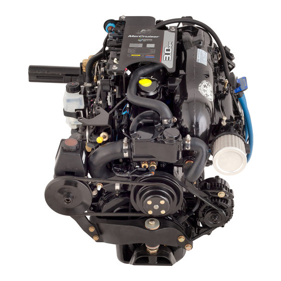
3.0 MPI
INSTALLATION MANUAL
Models Covered
Alpha
Notice
After completing installation, these instructions should be placed with the product for the owner's
future use.
Predelivery preparation instructions must be performed before delivering boat to the product owner.
Notice to Boat Manufacturer/Installer
Throughout this publication, dangers, warnings, cautions, and notices, (accompanied by
the International Hazard Symbol) are used to alert the manufacturer or installer to special
instructions concerning a particular service or operation that may be hazardous if
performed incorrectly or carelessly. These safety alerts follow ANSI standard Z535.6‑2006
for product safety information in product manuals, instructions, and other collateral
materials. Observe Them Carefully!
These Safety Alerts alone cannot eliminate the hazards that they signal. Strict compliance
to these special instructions when performing the service, plus common sense operation,
are major accident prevention measures.
Indicates a hazardous situation which, if not avoided, will result in death or serious injury.
Indicates a hazardous situation which, if not avoided, could result in death or serious
injury.
Indicates a hazardous situation which, if not avoided, could result in minor or moderate
injury.
Indicates a situation which, if not avoided, could result in engine or major component
failure.
Page i
Models covered
3.0 MPI
© 2007 Mercury Marine
Mercury, Mercury Marine, MerCruiser, Mercury MerCruiser, Mercury Racing, Mercury Precision Parts,
Mercury Propellers, Mariner, Quicksilver, #1 On The Water, Alpha, Bravo, Pro Max, OptiMax, Sport-Jet,
K-Planes, MerCathode, RideGuide, SmartCraft, Zero Effort, M with Waves logo, Mercury with Waves logo,
and SmartCraft logo are all registered trademarks of Brunswick Corporation. Mercury Product Protection
logo is a registered service mark of Brunswick Corporation.
Serial Number
1A300000 and above
NOTICE
NOTICE
DANGER
!
WARNING
!
CAUTION
!
NOTICE
90-899883183 DECEMBER 2007
Advertisement
Table of Contents

Related Manuals for Mercury MerCruiser 3.0 MPI


Summary of Contents for Mercury MerCruiser 3.0 MPI
- Page 1 Mercury, Mercury Marine, MerCruiser, Mercury MerCruiser, Mercury Racing, Mercury Precision Parts, Mercury Propellers, Mariner, Quicksilver, #1 On The Water, Alpha, Bravo, Pro Max, OptiMax, Sport-Jet, K-Planes, MerCathode, RideGuide, SmartCraft, Zero Effort, M with Waves logo, Mercury with Waves logo, and SmartCraft logo are all registered trademarks of Brunswick Corporation. Mercury Product Protection logo is a registered service mark of Brunswick Corporation.
- Page 2 NOTE: Refer to the appropriate Mercury MerCruiser Product Applications Manual for application recommendations. This installation manual has been written and published by Mercury MerCruiser to aid the boat manufacturer (OEM) in the installation of the products described herein. It is assumed that these personnel are familiar with marine product installation.
- Page 3 Manual Outline Important Information 1 - Important Information 2 - Boat Construction Boat Construction 3 - Exhaust System 4 - Fuel System Exhaust System 5 - Cooling System 6 - Drive System and Engine Installation 7 - Starting and Electrical Fuel System 8 - Remote Controls 9 - Predelivery Preparation and Storage...
- Page 4 Page iv...
-
Page 5: Table Of Contents
SECTION - 1 IMPORTANT INFORMATION SECTION 1 - IMPORTANT INFORMATION Table of Contents Torque Specifications for 3.0 MPI........................... 2 Quicksilver Products..............................2 Accessories ..............................2 Serial Number Decal Placement..........................2 Corrosion Protection..............................3 Anti‑fouling Paint..............................3 Emission Control Information Label........................4 Owner Responsibility ............................ -
Page 6: Torque Specifications For 3.0 Mpi
Accessories Quicksilver gauges, remote controls, steering systems, propellers, and other accessories are available for this product. Mercury MerCruiser recommends the use of Quicksilver parts on all applications. Refer to Mercury Precision Parts Accessories Guide for a complete listing. This Guide is available from:... -
Page 7: Corrosion Protection
IMPORTANT INFORMATION Corrosion Protection Mercury MerCruiser power packages are equipped with anodes to help protect them from galvanic corrosion under moderate conditions. However, for severe conditions or if using a stainless steel propeller, it is recommended that a Quicksilver Anti‑Corrosion Anode Kit and/or a MerCathode System with 2 additional transom mounted anode assemblies be installed (some models have a MerCathode System as standard equipment). -
Page 8: Emission Control Information Label
Boatbuilders and dealers may not remove the label or the part it is affixed to before sale. If modifications are necessary, contact Mercury MerCruiser about the availability of replacement decals before proceeding. -
Page 9: Owner Responsibility
SECTION - 1 IMPORTANT INFORMATION NOTE: When the CE mark is present in the lower right corner of the Emission Control Information Label on the engine, the Declaration of Conformance applies. Refer to the front page of this manual for further information. EMISSION CONTROL INFORMATION THIS ENGINE CONFORMS TO XXXX CALIFORNIA EMISSION... - Page 10 Beginning January 1, 2003, one Three‑Star or Four‑Star label will be included with each factory‑certified Mercury MerCruiser engine. All Mercury MerCruiser engines (500 hp and below) will have a Three‑Star Ultra Low Emission rating or Four‑Star Super Ultra Low Emission rating. The Star label identifies that these engines meet the California Air Resources Board's Sterndrive and Inboard marine engine 2007 and later exhaust emission standards.
-
Page 11: Hang Tag
SECTION - 1 IMPORTANT INFORMATION Hang Tag The Dealer must mark the appropriate box on one hang tag to match the Star label affixed to the boat. The dealer is responsible for displaying the hang tag in a visible location on the boat on display in California. - Page 12 IMPORTANT INFORMATION SECTION - 1 NOTES: Page 8 / 8 90-899883183 DECEMBER 2007...
- Page 13 SECTION - 2 BOAT CONSTRUCTION SECTION 2 - BOAT CONSTRUCTION Table of Contents Boat Construction..............................2 Transom Thickness and Surface........................2 Transom Cutout..............................2 Checking Transom Thickness...........................2 Engine Bed................................3 90-899883183 DECEMBER 2007 Page 1 / 4...
- Page 14 BOAT CONSTRUCTION SECTION - 2 Boat Construction Transom Thickness and Surface IMPORTANT: Transom thickness and surface plane (flatness) must be controlled where the sterndrive unit mounts. Transom Specifications Thickness Between 51 ‑ 57 mm (2 ‑ 2‑1/4 in.) for 203 mm (8 in.) to either side of the vertical center line Parallelism Inner and outer surfaces must be parallel within 3 mm (1/8 in.) Transom surfaces in area where transom assembly will be mounted (includes vertical as well Flatness...
- Page 15 SECTION - 2 BOAT CONSTRUCTION Engine Bed Description Measurement Difference between starboard and port engine mount 57.2 cm (22‑1/2 in.) Mount adjustment up and down (minimum) 6 mm (1/4 in.) NOTE: Although the engine mounts allow some adjustment, it is a good practice to ensure that the front and rear mount locations in the vessel are parallel and in the same plane.
- Page 16 BOAT CONSTRUCTION SECTION - 2 NOTES: Page 4 / 4 90-899883183 DECEMBER 2007...
- Page 17 SECTION - 3 EXHAUST SYSTEM SECTION 3 - EXHAUST SYSTEM Table of Contents Important Information.............................. 2 Carbon Monoxide Poisoning........................... 2 Good Ventilation ............................... 2 Poor Ventilation ..............................3 Measuring Exhaust Elbow Height........................... 3 General Information............................3 Boat Requirements............................4 Loading Requirements............................4 Loading the Boat with a Capacity Plate......................5 Example ..............................
-
Page 18: Important Information
EXHAUST SYSTEM SECTION - 3 Important Information NOTICE Improperly designing, installing, or modifying the engine’s exhaust system can introduce seawater or water from condensation into the combustion chambers, damaging the engine. The installing dealer or boat builder is responsible for proper installation of the exhaust system as explained in the installation instructions for the product. -
Page 19: Poor Ventilation
SECTION - 3 EXHAUST SYSTEM 1. Example of desired air flow through the boat. mc79553-1 Poor Ventilation Under certain conditions, permanently enclosed or canvas enclosed cabins or cockpits with insufficient ventilation may draw in carbon monoxide. Install 1 or more carbon monoxide detectors in your boat. -
Page 20: Boat Requirements
• Measurements used for official Mercury MerCruiser audit at the OEM boat builder must be performed on current production boats. No prototype hulls or light layup hulls will be considered for official audit purposes. -
Page 21: Loading The Boat With A Capacity Plate
SECTION - 3 EXHAUST SYSTEM Boats 8.84 m (29 ft.) long and greater than 8.84 m (29 ft.) long, that do not have a maximum rated swim platform weight capacity must add 226.80 kg (500 lb.) to the swim platform. Loading the Boat with a Capacity Plate For boats with a capacity plate, use the maximum load for persons and gear as listed on the capacity plate to determine the number of persons to place onto the boat for exhaust elbow... -
Page 22: Example
EXHAUST SYSTEM SECTION - 3 6. Load the swim platform if equipped. 7. Measure the exhaust elbow waterline height. IMPORTANT: View all boat seating as rows that are parallel to the transom of the boat. 8. Load a person weight into a seat, and measure the exhaust elbow waterline height after each person weight is loaded onto the boat. -
Page 23: Loading The Boat-Without A Capacity Plate
SECTION - 3 EXHAUST SYSTEM • 1060 lb. + 40 lb. = 1100 lb. 24862 Boat loading diagram Swim platform load MerCruiser person weight (three) MerCruiser person weight (one) MerCruiser person weight (four) MerCruiser person weight (two) Remainder MerCruiser person weight (five) Loading the Boat—Without a Capacity Plate For boats that do not display a capacity plate, the number of persons to be loaded onto the boat... -
Page 24: Example
EXHAUST SYSTEM SECTION - 3 Optional Cargo Distribution Aft storage Center storage Bow storage None None None None 100% None 100% None None None None 100% 6. Perform the first measurement with the swim platform loaded and the person measuring the waterline on the boat. - Page 25 SECTION - 3 EXHAUST SYSTEM • 225 lb. × 25% = 56.25 lb. • 56.25 lb. rounded down = 56 lb. 5. To determine the maximum number of passengers to load onto the boat, multiply 9 passengers by 165 lb. (MerCruiser person weight) to get a 1485 lb. (total passenger load) •...
-
Page 26: Clear Hose Measurement Method
EXHAUST SYSTEM SECTION - 3 Clear Hose Measurement Method 1. Obtain an 8–10 mm (5/16–3/8 in.) ID clear hose approximately 4.5 m (15 ft.) long. Install a metal fitting or a weight on one end of the hose to keep that end of the hose below the waterline. The fitting or weight must not restrict water from filling the clear hose. -
Page 27: Clear Hose Measurement Method From Seacock Or Muffler Drain
SECTION - 3 EXHAUST SYSTEM Clear Hose Measurement Method From Seacock or Muffler Drain IMPORTANT: Measure the exhaust elbow height to the waterline inside of the water lift muffler (instead of the water line outside of the boat) if equipped. IMPORTANT: The engine must have been operated previously to fill the muffler with water. - Page 28 EXHAUST SYSTEM SECTION - 3 NOTES: Page 12 / 12 90-899883183 DECEMBER 2007...
- Page 29 SECTION - 4 FUEL SYSTEM SECTION 4 - FUEL SYSTEM Table of Contents General Information..............................2 California Regulations for 2007—Low‑Permeation Fuel Hose................2 Special Information About Electric Fuel Pumps....................2 Fuel Delivery and Specifications..........................2 California Regulations for 2007—Low‑Permeation Fuel Hose................2 Fuel Delivery System ............................3 Special Information About Electric Fuel Pumps ..................
-
Page 30: General Information
FUEL SYSTEM SECTION - 4 General Information California Regulations for 2007—Low‑Permeation Fuel Hose California Regulations for New 2007 and Later Spark-Ignition Inboard/Sterndrive Pleasurecraft (3) Requirements of engine manufacturers and boat manufacturers under Option 2 and using Low Permeation Fuel Line Hose: (A) Each manufacturer that chooses Option 2 must provide written instructions, as part of the installation materials provided to purchasers of the engine, to use Low Permeation fuel Line Hose for the primary Fuel line connecting the fuel tank to the engine of any boat that is manufactured... -
Page 31: Fuel Delivery System
44° C (110° F) or less. The fuel delivery system is an integral part of the boat. Mercury MerCruiser makes no attempt in this manual to cover all aspects of design and integration of the fuel delivery system, due to a broad range of possible configurations and the numerous regulations and standards that cover this area. -
Page 32: Special Information About Electric Fuel Pumps
FUEL SYSTEM SECTION - 4 2. Using a digital vacuum gauge, measure the vacuum at the engine's fuel inlet. The maximum measured vacuum at the engine's fuel inlet must not exceed 6.9 kPa (2 in. Hg) through out engine operating range. IMPORTANT: Vacuum reading higher than specified can cause vapor locking with some of today's fuels. - Page 33 SECTION - 4 FUEL SYSTEM Description Specification Minimum fuel line diameter on single‑engine gasoline 10 mm (3/8 in.) installations Minimum fuel line diameter on multi‑engine gasoline 13 mm (1/2 in.) ID or larger installations • On Multi-Engine Gasoline Installations: Use a fuel pickup and fuel tank supply line for each engine.
- Page 34 FUEL SYSTEM SECTION - 4 NOTES: Page 6 / 6 90-899883183 DECEMBER 2007...
- Page 35 SECTION - 5 COOLING SYSTEM SECTION 5 - COOLING SYSTEM Table of Contents Specifications................................2 Seawater Pickup..............................2 3.0 MPI Water Flow Diagrams..........................3 Models with Seawater Cooling ......................... 3 Models with Closed Cooling ..........................4 90-899883183 DECEMBER 2007 Page 1 / 4...
-
Page 36: Specifications
COOLING SYSTEM SECTION - 5 Specifications Refer to Seawater Pump Output Test Section 9 to determine if a sufficient amount of water is being supplied to cool the engine. Alpha sterndrive seawater pump output for a 15 second period Drive unit gear ratio Minimum quantity liter (U.S. -
Page 37: 3.0 Mpi Water Flow Diagrams
SECTION - 5 COOLING SYSTEM 3.0 MPI Water Flow Diagrams Models with Seawater Cooling 32741 From Transom Engine circulating pump Seawater intake Engine block and cylinder head assembly Power steering cooler (if equipped) Intake and exhaust manifold Poppet valve assembly Exhaust elbow Thermostat housing 90-899883183 DECEMBER 2007... -
Page 38: Models With Closed Cooling
COOLING SYSTEM SECTION - 5 Models with Closed Cooling 32648 Seawater intake Engine block and cylinder head assembly From transom Exhaust manifold Power steering cooler (if equipped) Exhaust elbow Heat exchanger 10 - Poppet valve Coolant circulating pump 11 - Indicates glycol coolant flow Thermostat housing reservoir assembly... - Page 39 SECTION - 6 DRIVE SYSTEM AND ENGINE INSTALLATION SECTION 6 - DRIVE SYSTEM AND ENGINE INSTALLATION Table of Contents Transom Cutout............................... 3 Finding The Crankshaft Centerline........................3 Single Engine ............................. 3 Dual Engine ............................... 4 Finding Crankshaft Horizontal Center Line (X‑dimension)................4 90 Degree Tool Method ..........................
- Page 40 DRIVE SYSTEM AND ENGINE INSTALLATION SECTION - 6 Trim Cylinder Installation ......................... 47 Speedometer Connection..........................47 Alpha Notice: Increased Trim‑in Range Capability..................48 Alpha Trim Cylinder Spacer Removal......................48 Alpha Trim Cylinder Disassembly........................50 Alpha Trim Cylinder Reassembly........................51 Alpha Trim Cylinder Installation........................52 Page 2 / 54 90-899883183 DECEMBER 2007...
-
Page 41: Transom Cutout
SECTION - 6 DRIVE SYSTEM AND ENGINE INSTALLATION Lubricant, Sealant, Adhesives Tube Ref No. Description Where Used Part No. Loctite 271 Threadlocker Trim cylinder bolt threads 92-809819 Loctite 567 PST Pipe Sealant Brass fitting threads 92-809822 Battery cable connections Liquid Neoprene 92- 25711 3 All electrical connections Steering cable end... -
Page 42: Dual Engine
DRIVE SYSTEM AND ENGINE INSTALLATION SECTION - 6 2. If unknown, a compass can be used to locate the vertical centerline: Mark identical locations on each side of the boat 29.4 cm (12 in.) from the bottom of the hull. Position the fixed end of a compass at the marks and draw arcs on the transom. -
Page 43: 90 Degree Tool Method
SECTION - 6 DRIVE SYSTEM AND ENGINE INSTALLATION 90 DEGREE TOOL METHOD 1. Construct the 90 degree tool. 7689 34.5 cm (13‑9/16 in.) 1.2 m (4 ft) IMPORTANT: The 34.5 cm (13‑9/16 in.) dimension should only be raised or lowered after proper testing. -
Page 44: Cutting Out The Transom
DRIVE SYSTEM AND ENGINE INSTALLATION SECTION - 6 2. On the vertical crankshaft center line, measure up from the bottom of the transom to the X‑dimension selected previously. This is the crankshaft horizontal center line at the X‑dimension. 3. Draw a line perpendicular to the vertical center line at the crankshaft horizontal center line. 7692 7693 Single engine... - Page 45 SECTION - 6 DRIVE SYSTEM AND ENGINE INSTALLATION 5. Using a hole saw cut the two 51 mm (2 in.) holes for the steering lever cutout. If the hole saw cutout is made incorrectly, drive unit steering lever may contact transom causing limited steering travel.
-
Page 46: Checking The Transom Thickness
DRIVE SYSTEM AND ENGINE INSTALLATION SECTION - 6 Checking The Transom Thickness 1. Ensure that transom thickness and surface conform to specifications listed previously in Transom Thickness and Surface. 7697 Measuring thickness Suitable mandrel to check for uniform transom thickness Measuring flatness Transom Connections Installing Gimbal Housing... -
Page 47: Connecting Speedometer Pickup
SECTION - 6 DRIVE SYSTEM AND ENGINE INSTALLATION 6. Secure the transom assembly with the hardware as shown. Torque the hardware. Description lb. in. lb. ft. Transom assembly hardware IMPORTANT: Tighten the transom assembly fasteners using an X‑pattern torque sequence, starting from the middle fasteners. -
Page 48: Alpha Gear Lube Monitor Connection At Gimbal Housing
DRIVE SYSTEM AND ENGINE INSTALLATION SECTION - 6 2. Connect a 4 mm (5/32 in.) speedometer hose (not provided) from speedometer to barb fitting. Secure hose with tie strap. 7703 Typical Male quick connect Hose Female quick connect Tie strap Barbed fitting CAUTION A ruptured speedometer hose can introduce water into the bilge, causing boat damage or... -
Page 49: Alternative Mounting Of Gear Lube Monitor On Transom
SECTION - 6 DRIVE SYSTEM AND ENGINE INSTALLATION NOTE: The quick release button on hose fitting must be positioned away from water inlet fitting, or block‑off plate if equipped. Release button must not contact water fitting or block‑off plate, if equipped. -
Page 50: Power Trim Pump Connections And Filling
DRIVE SYSTEM AND ENGINE INSTALLATION SECTION - 6 • Is close to the battery so that trim pump battery leads can be connected. • Allows easy access to trim pump oil fill and vent locations. • Is in an area where pump will not be exposed to water. •... -
Page 51: Trim Limit Switch Connection
SECTION - 6 DRIVE SYSTEM AND ENGINE INSTALLATION 2. Connect power trim pump control harness to trim pump. 7699 Control harness Trim pump connector 7701 Fill cap assembly (top and Fill cap on trim pump reservoir underneath side views) Trim Limit Switch Connection 1. -
Page 52: Installing Steering System For The Alpha Drive
DRIVE SYSTEM AND ENGINE INSTALLATION SECTION - 6 4. Make all transom wiring connections and secure with clamps. Transom harness connector should be placed in a safe location and will be connected to the engine after the engine is installed. Installing Steering System for the Alpha Drive Hydraulic (Helm) Steering If your power package is equipped with Compact Hydraulic Steering, refer to the Compact... - Page 53 SECTION - 6 DRIVE SYSTEM AND ENGINE INSTALLATION 5. Torque pivot bolts. Bend washer tabs against corresponding flats on bolt heads. 7707 Manual steering Tab washers Pivot bolts Ridge Description lb. in. lb. ft. Pivot Bolts NOTICE Fastening any items to the steering cables or outer casings prevents normal operation. The steering cable and outer casing must be free to move back and forth.
-
Page 54: Power Steering Instalation
NOTE: For dual installations, power steering unit can be mounted on port or starboard transom assembly. Measure exact distance between power package centerlines. Select a tie bar from Mercury Precision Parts / Quicksilver Accessory Guide. Refer to tie bar installation instructions before proceeding. - Page 55 SECTION - 6 DRIVE SYSTEM AND ENGINE INSTALLATION 3. Remove the upper and lower pivot bolts and ensure that the threads are well lubricated. 7710 Bushings Upper and lower pivot bolt Protective shipping caps Tube Ref No. Description Where Used Part No.
- Page 56 DRIVE SYSTEM AND ENGINE INSTALLATION SECTION - 6 NOTE: It may be necessary to tighten the pivot bolts further to align the flats on bolt head with the tabs on the washer. 7711 Pivot bolt Bent tab Description lb. in. lb.
- Page 57 SECTION - 6 DRIVE SYSTEM AND ENGINE INSTALLATION NOTE: Insert the clevis pin from the top to ensure that the cotter pin hole is as shown in the diagram. 7822 Clevis Clevis pin Steering lever Cotter pin Tube Ref No. Description Where Used Part No.
- Page 58 DRIVE SYSTEM AND ENGINE INSTALLATION SECTION - 6 NOTICE Fastening any items to the steering cables or outer casings prevents normal operation. The steering cable and outer casing must be free to move back and forth. Do not fasten any items to the steering cable and outer casing.
-
Page 59: Engine Installation
SECTION - 6 DRIVE SYSTEM AND ENGINE INSTALLATION Engine Installation Transom Preparation for the Alpha Drive IMPORTANT: Exhaust pipe and gimbal housing mating surfaces must be clean and free of nicks and scratches and O‑ring must be properly seated in groove or water and exhaust may leak into boat. -
Page 60: 3.0 Mpi Engine Preparation
DRIVE SYSTEM AND ENGINE INSTALLATION SECTION - 6 4. Install exhaust pipe assembly as shown, using 4 bolts and lockwashers. Torque bolts. 7838 Exhaust pipe Bolts and lockwashers (4) Description lb. in. lb. ft. Exhaust pipe bolts 5. Position rear engine mount attaching hardware on inner transom plate mounts as shown. 7839 Fiber Washer (2) Locknut (2) -
Page 61: Fuel Inlet Fitting
SECTION - 6 DRIVE SYSTEM AND ENGINE INSTALLATION IMPORTANT: There is a fuse located at the starter solenoid. Do not remove this fuse. 23832 Starter solenoid Positive (+) battery cable location 90 amp fuse ‑ do not remove Protective rubber boot, pulled back for clarity After the battery cables are connected, apply a thin coat of sealant to the terminals. -
Page 62: 3.0 Mpi Installation
DRIVE SYSTEM AND ENGINE INSTALLATION SECTION - 6 WARNING Failure to comply with the required boating standards can result in serious injury or death. Always adhere to all applicable Marine Regulations (United States Coast Guard [USCG], European Union ‑ Recreational Craft Directive [EU‑RCD], etc.) and the standards they reference (American Boat and Yacht Council [ABYC], Society of Automotive Engineers [SAE], International Standards Organization [ISO], etc.) when installing the fuel delivery system. - Page 63 SECTION - 6 DRIVE SYSTEM AND ENGINE INSTALLATION IMPORTANT: The center lifting eye (on the thermostat housing) is for engine alignment only. Do not use the center lifting eye to lift the entire engine. 32840 Engine lifting eyes Center lifting eye 2.
- Page 64 DRIVE SYSTEM AND ENGINE INSTALLATION SECTION - 6 4. On side mount models, loosen both side engine mount adjustment nuts. 7789 7791 3.0 MPI side mount model Engine mount (2) Adjustment nut (2) Jam nut (2) NOTE: On side mount models, an installation jig (91‑806794A1) can be used to align and adjust engine mounts.
- Page 65 SECTION - 6 DRIVE SYSTEM AND ENGINE INSTALLATION Pull the oil drain hose out until it is 152 mm (6 in.) from the propeller. Position the alignment clip on the oil drain hose just inside of the boat hull against the flange.
-
Page 66: Initial Engine Alignment
DRIVE SYSTEM AND ENGINE INSTALLATION SECTION - 6 Initial Engine Alignment 1. Ensure that the dust cover is removed or folded back out of the way. 7783 Dust cover 2. Attempt to insert the solid end of the alignment tool through the gimbal bearing and into the engine coupler splines. - Page 67 SECTION - 6 DRIVE SYSTEM AND ENGINE INSTALLATION 5. Repeat alignment procedure until the alignment tool slides freely with normal force all the way into and out of engine coupler splines. Do not turn the alignment tool. 7786 Alignment tool Engine coupler Gimbal bearing IMPORTANT: Finished boat stringer must position engine so that a minimum mount adjustment...
-
Page 68: Exhaust Connections
DRIVE SYSTEM AND ENGINE INSTALLATION SECTION - 6 Tighten the bottom nut to hold the engine in place. Then release the tension. 7964 Side‑mount model Engine mount Tab washer Top nut Bottom nut 8. Recheck alignment with alignment tool. The tool must enter the coupling splines freely. If not, readjust the front mounts. -
Page 69: Continuity Wire Connection
We recommend using Quicksilver Instrumentation and Wiring Harnesses. On dual station applications, oil pressure and water temperature senders on the engine must be changed. Refer to the appropriate Mercury Precision Parts Accessories Guide for assistance. The four basic gauges that must be used with the engine are: •... -
Page 70: Audio Warning System Connections, If Equipped
DRIVE SYSTEM AND ENGINE INSTALLATION SECTION - 6 1. Route the instrumentation wiring harness back to the engine, avoiding hot spots or moving parts. If an extension harness is required, secure the connection properly. 2. Fasten the harnesses to the boat at least every 46 cm (18 in.), using appropriate fasteners. 3. -
Page 71: Power Trim Electrical Connection
SECTION - 6 DRIVE SYSTEM AND ENGINE INSTALLATION Power Trim Electrical Connection ABYC (American Boat and Yacht Council) installation recommends installing a battery switch in the positive conductor of any battery or battery bank with CCA rating greater than 800 amperes. (See ABYC for additional information) ABYC further recommends, if a boat is equipped with a battery switch, the power trim pump may not be connected to the continuously energized circuit (battery). -
Page 72: Fluid Connections
DRIVE SYSTEM AND ENGINE INSTALLATION SECTION - 6 Fluid Connections GEAR LUBE MONITOR CONNECTION IMPORTANT: Route hoses to determine the minimum length of hose needed, then trim the excess to avoid low spots in the system. Avoid kinks and route in a straight path. 1. -
Page 73: Seawater Pickup
SECTION - 6 DRIVE SYSTEM AND ENGINE INSTALLATION SEAWATER PICKUP 1. Connect the water inlet hose to the water inlet fitting on the transom. 7802 Water inlet tube Hose clamp Seawater inlet hose 2. Secure with a hose clamp. COOLANT RECOVERY SYSTEM NOTE: This section applies to models with closed cooling only. -
Page 74: Cable Installation
Alpha Models SHIFT CABLE TRAVEL We recommend the use of a Quicksilver remote control and cable. Refer to Mercury Precision Parts Accessories Guide for selection. However, if a control other than Quicksilver is to be used, control must provide specified shift cable travel (at the shift plate end). -
Page 75: Separate Shift And Throttle Controls
SECTION - 6 DRIVE SYSTEM AND ENGINE INSTALLATION Description Specification Shift cable travel at the shift plate end with a 0.8‑9 kg (15‑20 lb) load applied 73 mm (2‑7/8 in.)‑80 mm (3‑1/8 in.) to the cable end guide NOTE: On engines with Alpha drives, the measurement indicated above can be taken by installing the remote control shift cable and using the shift assist assembly (provided) to place the proper load on the shift cable. -
Page 76: Installation
DRIVE SYSTEM AND ENGINE INSTALLATION SECTION - 6 Order a spacer kit to connect the remote control shift cable when shift assist assembly is not used. c c d 32845 Clevis pin Spacer Washer Cotter pin NOTE: Do not discard shift assist assembly until after it is used below. IMPORTANT: Shift cable must be connected at the remote control for the appropriate rotation (LH or RH) drive unit, as explained following: RIGHT‑HAND ROTATION ‑... - Page 77 SECTION - 6 DRIVE SYSTEM AND ENGINE INSTALLATION 2. Remove shift cable attaching hardware. 32846 Shift assist Shift plate 3. Install the intermediate cable. 32823 4. Secure the brass barrel retainer with the cotter pin. 5. Secure the cable end guide with washers (one on each end of the end guide) and cotter pin. 6.
- Page 78 DRIVE SYSTEM AND ENGINE INSTALLATION SECTION - 6 Measure distance between marks "a" and "b" and mark position "c" half‑way between marks "a" and "b." 7815 7. Temporarily install control cable end guide into shift lever and insert anchor pin. 8.
-
Page 79: Throttle Cable Installation And Adjustment
SECTION - 6 DRIVE SYSTEM AND ENGINE INSTALLATION 32844 Without shift assist assembly Remote control shift cable Washer Clevis pin Spacer Cotter pin (existing) (not shown) Washer (existing) Spring (existing) (not shown) Cotter pin (existing) Washer (existing) Throttle Cable Installation and Adjustment 1. -
Page 80: Alpha Sterndrive Installation
DRIVE SYSTEM AND ENGINE INSTALLATION SECTION - 6 Alpha Sterndrive Installation 1. Remove the trim cylinder support and dust cover from the bell housing studs. Retain the elastic stop nuts and flat washers. 7713 Typical Dust cover Trim cylinder support 2. - Page 81 SECTION - 6 DRIVE SYSTEM AND ENGINE INSTALLATION 3. Push the dribble valve stem in until gear lube appears, then release. 7851 Dribble valve stem 4. If the gear lube monitor is below the "OPERATING RANGE" line, fill the gear lube monitor with specified fluid.
- Page 82 DRIVE SYSTEM AND ENGINE INSTALLATION SECTION - 6 8. Lubricate the sterndrive U‑joint O‑rings and drive shaft splines. A grease packet for this procedure is provided with the sterndrive packaging. 7853 U‑joint O‑rings Drive shaft splines Tube Ref No. Description Where Used Part No.
- Page 83 SECTION - 6 DRIVE SYSTEM AND ENGINE INSTALLATION 10. Position the bell housing shift shaft coupler so that the slot in the coupler is positioned straight, fore and aft. Do this by placing remote control shift lever in: forward gear position for RH drives or reverse gear position for LH drives.
- Page 84 DRIVE SYSTEM AND ENGINE INSTALLATION SECTION - 6 14. Turn the drive unit shift shaft clockwise while simultaneously turning propeller shaft counter‑clockwise so that the shift shaft is forward . 7856 Drive unit shift shaft IMPORTANT: Install the RH or LH drive unit on the appropriate transom assembly when making dual engine installations.
-
Page 85: Trim Cylinder Installation
SECTION - 6 DRIVE SYSTEM AND ENGINE INSTALLATION Secure the sterndrive to the bell housings using fasteners as shown. Torque the fasteners to specifications. 7858 Locknut and flat washers Locknut and continuity circuit washer Description lb‑in. lb‑ft Sterndrive unit fasteners –... -
Page 86: Alpha Notice: Increased Trim-In Range Capability
DRIVE SYSTEM AND ENGINE INSTALLATION SECTION - 6 3. Push down to secure. 4803 Male end of speedometer tube fitting Female end of speedometer tube fitting Ensure that the speedometer tube is secured and out of the way of moving parts. 8029 Male end of speedometer tube fitting Female end of speedometer tube... - Page 87 SECTION - 6 DRIVE SYSTEM AND ENGINE INSTALLATION 2. Disconnect "DOWN" trim hose from hydraulic connector on gimbal housing. Plug holes with 22‑38609 plug. 7843 "UP" hose "DOWN" hose "UP" port on trim cylinder Hydraulic connector 3. Remove front power trim cylinder mounting hardware. 4827 Front anchor pin E‑ring (port and starboard) (2)
-
Page 88: Alpha Trim Cylinder Disassembly
DRIVE SYSTEM AND ENGINE INSTALLATION SECTION - 6 Alpha Trim Cylinder Disassembly WARNING On some boats, increased trim‑in range can cause handling problems at high speeds, resulting in personal injury or death. We recommend that only qualified personnel adjust the trim‑in limit inserts and test the boat for handling problems. -
Page 89: Alpha Trim Cylinder Reassembly
SECTION - 6 DRIVE SYSTEM AND ENGINE INSTALLATION Alpha Trim Cylinder Reassembly CAUTION Contamination can damage the hydraulic system or cause the system to malfunction. Failure of power trim or steering components can result in injury or product damage. Ensure that the work area, shop tools and all components are clean and lint free during reassembly. -
Page 90: Alpha Trim Cylinder Installation
DRIVE SYSTEM AND ENGINE INSTALLATION SECTION - 6 5. Position trim cylinder rear connecting ends. 7848 Port trim cylinder Connecting ends (offset as shown) Starboard trim cylinder Alpha Trim Cylinder Installation 1. Install trim cylinders forward mounting hardware. 2. Coat area in trim cylinder between bushings with lubricant. 3. - Page 91 Where Used Part No. 2-4-C Marine Lubricant with Trim cylinder 92-802859A 1 Teflon 9. Reconnect trim hoses after air bleeding power trim cylinders and hoses following procedures outlined in Mercury MerCruiser Service Manual 14. 90-899883183 DECEMBER 2007 Page 53 / 54...
- Page 92 DRIVE SYSTEM AND ENGINE INSTALLATION SECTION - 6 NOTES: Page 54 / 54 90-899883183 DECEMBER 2007...
- Page 93 SECTION - 7 STARTING AND ELECTRICAL SECTION 7 - STARTING AND ELECTRICAL Table of Contents Information and Check List – Installation using 14 pin connection................2 Battery..................................2 Battery Cables..............................2 Power Harness..............................3 Electrical System Precautions...........................3 Boat Harness and Installation Connections......................4 Engine Harness and Accessory Power Supply....................4 Boat Wiring................................4 Single Station .............................
-
Page 94: Information And Check List - Installation Using 14 Pin Connection
SECTION - 7 Information and Check List – Installation using 14 pin connection • Refer to Mercury Precision Parts and Accessories Guide or OEM Rigging and Accessories Guide for part number information 1. Ensure that the 14 pin boat harness is the correct length to properly route from the boat dash to the locking 14 pin electrical connector on the engine. -
Page 95: Power Harness
SECTION - 7 STARTING AND ELECTRICAL Average cable length Cable gauge 2.9‑3.7 m (9‑1/2 ‑ 12 ft) 70 mm 2 (00) 3.7‑4.6 m (12 ‑ 15 ft) 95 mm 2 (000) 4.6‑5.8 m (15 ‑ 19 ft) 120 mm 2 (0000) Power Harness IMPORTANT: On all models equipped with DTS or Emissions Control you must install the appropriate power harness for your application. -
Page 96: Boat Harness And Installation Connections
STARTING AND ELECTRICAL SECTION - 7 Boat Harness and Installation Connections Engine Harness and Accessory Power Supply If the engine harness is used to supply power for boat accessories (lights, blower, pumps, stereo, or any other electrical device using the engine wiring harness for power), the maximum accessory power available on the 14‑pin wiring harness is 15 amps. -
Page 97: Boat Harness Installation Guidelines-Mpi Sterndrive
SECTION - 7 STARTING AND ELECTRICAL • Use the proper length harness from the Y to the upper station. 25132 Y‑adapter for dual helm installations Boat Harness Installation Guidelines—MPI Sterndrive BOAT HARNESS DEUTSCH CONNECTOR TO ENGINE Select the boat harness by length. Boat Harness Length of the Boat Boat Harness and Key Switch... -
Page 98: Trim Switch
Typical key switch with momentary "stop" switch for MPI models Black wire with eye terminals Eye terminals connected to momentary switch Black/yellow stripe wire with eye terminals. Momentary switch TRIM SWITCH The trim switch connection is only used on Mercury outboards. Page 6 / 22 90-899883183 DECEMBER 2007... -
Page 99: Neutral Switch
SECTION - 7 STARTING AND ELECTRICAL MerCruiser models require a separate trim harness from the trim control to power the trim pump connection. A Y‑harness is available with adapters to connect the dual helm power trim harnesses together to connect to the power trim pump. Use the power trim adapter harness for the single helm harness connection. -
Page 100: Optional E Stop
OPTIONAL E STOP The E stop lanyard switch connection is used on Mercury outboards and can be used on MerCruiser MPI engines. The black and black/yellow wires are connected together through a lanyard switch that is normally open. - Page 101 SECTION - 7 STARTING AND ELECTRICAL If SmartCraft instrumentation is used, connect to a a SmartCraft junction box. If a combination of SmartCraft and analog is used, an AGI (analog gauge interface) kit is used to provide analog instrumentation. The AGI harness connects to the junction box along with the SmartCraft connection.
-
Page 102: Can P (Can 1) Connections
STARTING AND ELECTRICAL SECTION - 7 A system link adapter can be used to connect SmartCraft link gauges without a System Gauge (requires resetting tach signal to digital with CDS or DDT) fuel tank and trim gauge setting will be defaulted. - Page 103 The fuel tank, auxiliary tank, and paddle wheel harness has been changed on MerCruiser to match the harness used by Mercury Outboard. The new harness is needed to replace the original harness for any 10‑pin engine installation using SmartCraft fuel level or paddle wheel.
- Page 104 STARTING AND ELECTRICAL SECTION - 7 • SmartCraft sensor connections Secure the wiring and position the engine connector out of the way until the engine is installed. After the engine is in place, make the single connection between the transom and the engine. 25155 Transom harness—MPI 16‑pin connector to engine harness...
-
Page 105: Transom Harness-Mpi
SECTION - 7 STARTING AND ELECTRICAL Wiring Diagrams Transom Harness—MPI BLK-PNK PNK-DK BLU GRA-BLK BLK-PNK GRA-BLK WHT-LT BLU GRA-BLK ORN-WHT BLK-PNK WHT-LT BLU PNK-DK BLU ORN-PNK ORN-WHT 23812 Steering Analog trim Pitot Ground Analog trim Digital Trim Mercathode 16 pin connector 90-899883183 DECEMBER 2007 Page 13 / 22... -
Page 106: Boat Harness
STARTING AND ELECTRICAL SECTION - 7 Boat Harness DRAWING 12340 14‑pin Deutsch connector Warning horn Key switch connector Accessory relay connection (15‑amp) Trim switch (outboard only) Gauge connector/CAN connector for SmartCraft Neutral switch 10 - CAN P (CAN 1) with resistor cap Lanyard switch (sterndrive) or key switch + connection 11 -... -
Page 107: Diagram
SECTION - 7 STARTING AND ELECTRICAL DIAGRAM DKBLU PPL_WHT PPL_WHT BLK_YEL YEL_RED GRN_WHT BLU_WHT DKBLU YEL_RED BLK_YEL YEL_RED BLU_WHT GRN_WHT PPL_WHT BLK_YEL YEL_RED 12339 14‑pin Deutsch connector Warning horn Key switch connector Accessory relay connection (15‑amp) Trim switch (outboard only) Gauge connector Neutral switch 10 -... -
Page 108: Analog Gauge Harness
STARTING AND ELECTRICAL SECTION - 7 Analog Gauge Harness DRAWING 12312 Connector to boat harness Trim Ground (–) Tach CAN (+) or spare Key on (+) CAN (–) or spare Temp 10 - 12V (+) DIAGRAM BRN_WHT DK_BLU BRN_WHT LTBLU LTBLU DK_BLU 12318... -
Page 109: Helm Trim Control Switch To Power Trim Pump Harness Assembly (Control Harness Assembly)
SECTION - 7 STARTING AND ELECTRICAL Helm Trim Control Switch to Power Trim Pump Harness Assembly (Control Harness Assembly) 12323 Connection to control box Connections to trim limit switch Connection to trim pump 90-899883183 DECEMBER 2007 Page 17 / 22... - Page 110 STARTING AND ELECTRICAL SECTION - 7 GRN-WHT PPL-WHT DK BLU-WHT 12322 Connection to control box Connections to trim limit switch Connection to trim pump Page 18 / 22 90-899883183 DECEMBER 2007...
-
Page 111: Power Trim System (Non-Dts)
SECTION - 7 STARTING AND ELECTRICAL Power Trim System (Non‑DTS) BLU/WHT GRN/WHT BLU/WHT GRN/WHT RED/PPL GRN/WHT PPL/WHT BLU/WHT 7866 20 amp fuse 110‑amp fuse Ground bolt (floor mount) Y‑harness (optional) Up solenoid Neutral switch to instrument wiring harness Down solenoid Trim limit switch 90-899883183 DECEMBER 2007 Page 19 / 22... -
Page 112: 14-Pin Engine Harness Connector
STARTING AND ELECTRICAL SECTION - 7 14‑Pin Engine Harness Connector Mechanical 14‑Pin Connector Pin‑Out Wire Color Function PINK + 12 Volt BLACK Ground (‑) PURPLE Wake DK GREEN/YELLOW E‑Stop DK BLUE Analog oil pressure WHITE CAN 1+ LT BLUE CAN 1‑ Open Spare Open... -
Page 113: Configuring Analog/Digital Tachometer Signal Through Pcm
The Computer Diagnostic System (CDS) can communicate with the DTS command module. However, the CDS will not configure TachLink Config‑Enable, which configures the PCM for using an AGI and other special SmartCraft gauge configurations To configure the PCM, contact the following Mercury MerCruiser representatives: 90-899883183 DECEMBER 2007 Page 21 / 22... - Page 114 STARTING AND ELECTRICAL SECTION - 7 Customer Contact Dealers Contact MerCruiser Dealer Technical Service (1‑405‑743‑6555) Contact your local product application engineer (PAE) for assistance. Boat Builders If they cannot be reached, contact MerCruiser OEM Technical Service (1‑405‑743‑6555) Page 22 / 22 90-899883183 DECEMBER 2007...
- Page 115 SECTION - 8 REMOTE CONTROLS SECTION 8 - REMOTE CONTROLS Table of Contents Steering Helm and Cable............................2 Steering Cable Specifications..........................3 Sterndrive Shift Cable Information.......................... 4 Propeller Rotation..............................4 Checking Alpha Shift Cable Installation and Adjustment..................4 Troubleshooting Shift Problems..........................7 90-899883183 DECEMBER 2007 Page 1 / 10...
-
Page 116: Steering Helm And Cable
REMOTE CONTROLS SECTION - 8 Lubricant, Sealant, Adhesives Tube Ref No. Description Where Used Part No. 2-4-C Marine Lubricant with Teflon Shift cable end 92-802859A 1 Steering Helm and Cable Transom assembly is shipped with the steering cable guide tube preset for cables with end dimensions that comply with ABYC standards as outlined in the NMMA certification handbook. -
Page 117: Steering Cable Specifications
SECTION - 8 REMOTE CONTROLS Steering Cable Specifications IMPORTANT: Power steering pump lugging (squealing) in a hard right turn (against lock) may mean a steering cable has been installed that does not have the correct dimensions. 7254 Coupler nut ‑ 7/8 ‑ 14 UNF ‑ 28 thread 15.9 mm (5/8 in.) maximum diameter end fitting 29.8 cm (11‑3/4 in.) minimum... -
Page 118: Sterndrive Shift Cable Information
REMOTE CONTROLS SECTION - 8 Sterndrive Shift Cable Information Propeller Rotation Propeller rotation for sterndrive can be clockwise or counterclockwise, as viewed from the aft (rear) end of the propeller. 4802 4747 Clockwise rotation Counterclockwise rotation Checking Alpha Shift Cable Installation and Adjustment IMPORTANT: Do not use excessive force when holding pressure on the drive unit shift cable. - Page 119 SECTION - 8 REMOTE CONTROLS On right‑hand rotation drive units, place the drive unit into gear by pushing in on the drive unit shift cable while simultaneously rotating the propeller shaft counter‑clockwise until the shaft stops. Maintain a light pressure on the drive unit shift cable to hold it at the end of its travel.
- Page 120 REMOTE CONTROLS SECTION - 8 On right‑hand rotation drive units, place the drive unit into gear by pulling out on the drive unit shift cable while simultaneously rotating the propeller shaft clockwise until the shaft stops. Maintain a light pressure on the drive unit shift cable to hold it at the end of its travel.
-
Page 121: Troubleshooting Shift Problems
SECTION - 8 REMOTE CONTROLS On right‑hand propeller rotation drive units, while turning the propeller shaft clockwise, move the remote control shift handle into full reverse position. The clutch should engage before the shift lever comes to a stop. If the clutch does not engage, loosen the adjustable stud on the shift lever and move it up in the slot until the clutch engages with the reverse gear. - Page 122 REMOTE CONTROLS SECTION - 8 7872 Improper cable bend 2. Ensure that when the shift cable from the control box is led through the side gunnel of the hull, it does not have any extremely sharp bends in it as this will cause stiff shifting. IMPORTANT: Remote control cables MUST BE THE CORRECT LENGTH;...
- Page 123 SECTION - 8 REMOTE CONTROLS 5. Ensure that the cable is not permanently kinked. 6. Ensure that there is proper clearance for cable movement when the control box is installed in the side panel. The cables must have room to move up and down when the control handle is shifted into either FORWARD or REVERSE.
- Page 124 REMOTE CONTROLS SECTION - 8 NOTES: Page 10 / 10 90-899883183 DECEMBER 2007...
- Page 125 SECTION - 9 PREDELIVERY PREPARATION AND STORAGE SECTION 9 - PREDELIVERY PREPARATION AND STORAGE Table of Contents Predelivery Preparation............................2 Engine Oil................................2 Checking ..............................3 Filling ................................. 3 Power Steering Fluid............................4 Power Trim Pump.............................. 4 Filling Coolant Recovery Bottle ........................6 Trim Limit Switch Adjustment..........................6 Analog Guages ............................
-
Page 126: Predelivery Preparation
PREDELIVERY PREPARATION AND STORAGE SECTION - 9 Lubricant, Sealant, Adhesives Tube Ref No. Description Where Used Part No. Perfect Seal Aft heat exchanger plug 92-34227 1 Special Lubricant 101 Propeller shaft splines 92-802865Q02 High Performance Gear Lubricant Gear Lube Monitor 92-858064K01 Power Trim and Steering Fluid Power steering pump... -
Page 127: Checking
Engine Oil Capacity Fluid type 3.0 MPI 3.8 L (4 US qt) Mercury Full‑Synthetic MerCruiser Oil 20W‑40 IMPORTANT: Always use the dipstick to determine the exact quantity of oil or fluid required. 3. Replace the fill cap. 90-899883183 DECEMBER 2007... -
Page 128: Power Steering Fluid
PREDELIVERY PREPARATION AND STORAGE SECTION - 9 Power Steering Fluid IMPORTANT: Use only the specified lubricant. IMPORTANT: Do not run the power steering system dry. That will damage the pump. 1. Position the sterndrive unit so that it is straight back. 2. - Page 129 SECTION - 9 PREDELIVERY PREPARATION AND STORAGE 5. Observe the oil level in the reservoir. 7876 The oil level should be within the "MIN" and "MAX" lines on the reservoir. Reservoir "MIN" and "MAX" lines 6. Unscrew and remove the fill cap assembly from the reservoir. NOTE: The fill cap and cap vent are an assembled as a unit and should not be separated.
-
Page 130: Filling Coolant Recovery Bottle
PREDELIVERY PREPARATION AND STORAGE SECTION - 9 Filling Coolant Recovery Bottle NOTE: This section applies to Closed Cooled models only. 1. Remove cap from coolant recovery reservoir and fill to FULL mark with coolant solution. Reinstall cap. 2. Recheck coolant level after first WOT boat test and add coolant, if necessary. 3. -
Page 131: Trim Position Sender Adjustment
SECTION - 9 PREDELIVERY PREPARATION AND STORAGE Slowly turn trim limit switch counterclockwise until trim cylinders extend to dimension shown. 7880 Trim limit switch Rotate Counterclockwise To Adjust 7881 Alpha trim cylinder extended Maximum520 mm (20‑3/4 in.) Retighten screws when adjustment is correct. Trim position sender adjustment ANALOG GAUGES 1. -
Page 132: Drive Unit Gear Lube Monitor
PREDELIVERY PREPARATION AND STORAGE SECTION - 9 4. Rotate trim position sender as required to show full DOWN/IN position on dashboard instrument as shown. 7883 Trim gauge needle 5. Tighten retaining screws and turn ignition key to the "OFF" position. 7882 Retaining screws Trim position sender... -
Page 133: Propeller Installation (Alpha)
SECTION - 9 PREDELIVERY PREPARATION AND STORAGE 3. Ensure that the rubber gasket is inside the gear lube monitor cap. 4. Install the gear lube monitor cap. Do not overtighten. 5. Recheck gear lube level after first use. Propeller Installation (Alpha) WARNING Rotating propellers can cause serious injury or death. -
Page 134: Engine Connections
PREDELIVERY PREPARATION AND STORAGE SECTION - 9 3. Bend the 3 tabs down into grooves. 5301 Propeller shaft splines Drive sleeve adapter Forward thrust hub Locking tab washer Flo‑torque II drive hub Propeller nut Propeller Description lb. in. lb. ft. Alpha propeller nutAlpha propeller nut Then align tabs with grooves. -
Page 135: Boat In The Water Tests
With the boat in the water, the drive unit in forward gear, and the engine at normal operating temperature, the engine should idle at the RPM specified in appropriate Mercury MerCruiser Operation, Maintenance, and Warranty Manual. If the idle speed is incorrect, check the throttle cable and adjust as necessary. -
Page 136: Priming The Fuel System
Flushing the Power Package Your boat comes equipped with through the sterndrive water pickups. See Sterndrive Water Pickups (following) for the flushing procedure. Consult your authorized Mercury MerCruiser dealer for further explanation. IMPORTANT: Alpha engines with the sterndrive water inlet blocked off at the gimbal housing, and... -
Page 137: Sterndrive Water Pickups
SECTION - 9 PREDELIVERY PREPARATION AND STORAGE STERNDRIVE WATER PICKUPS This Mercury MerCruiser sterndrive is equipped with side water pickups. Side pickups require the flushing attachment (44357Q 2). 5773 Side Pickup NOTE: Flushing is needed only for salty, brackish, mineral‑laden, or polluted water applications. -
Page 138: Alpha Seawater Pump Output Test
PREDELIVERY PREPARATION AND STORAGE SECTION - 9 7. Depress the throttle only button and slowly advance the throttle until the engine reaches 1300 RPM (± 100 RPM). 8. Observe the water temperature gauge to ensure that the engine is operating in the normal range. -
Page 139: Cold Weather Or Extended Storage
3. If the boat is to be placed in storage with fuel containing alcohol in fuel tanks (if fuel without alcohol is not available): Fuel tanks should be drained as low as possible and Mercury/ Quicksilver Gasoline Stabilizer for Marine Engines added to any fuel remaining in the tank. -
Page 140: Engine And Fuel System Preparation
SECTION - 9 6. Operate the engine sufficiently to bring it up to normal operating temperature and allow fuel with Mercury/Quicksilver Gasoline Stabilizer to circulate through the fuel system. Shut off the engine. 7. Change the oil and oil filter. -
Page 141: Draining The Seawater System
SECTION - 9 PREDELIVERY PREPARATION AND STORAGE 3. Close the fuel shut off valve, if equipped. Disconnect and plug the fuel inlet fitting if not equipped with a fuel shut off valve. 4. Connect the remote fuel tank (with the fogging mixture) to the fuel inlet fitting. IMPORTANT: Supply cooling water to the engine. -
Page 142: Draining The Seawater Section Of Models With Closed Cooling
PREDELIVERY PREPARATION AND STORAGE SECTION - 9 3. Push the quick connect fitting release buttons and remove the blue drain hoses from the bracket. 32559 Release button (to engine block) Blue drain hoses T‑handle Hose guide Release button (to exhaust manifold) 4. - Page 143 SECTION - 9 PREDELIVERY PREPARATION AND STORAGE 2. Remove the drain plug from the aft drain plug from the heat exchanger. 7184 Aft heat exchanger drain plug 3. Clean out the drain hole with a stiff piece of wire until the entire system is drained. NOTE: It may be necessary to lift or bend hoses to allow water to drain completely.
-
Page 144: Clearing Clogged Blue Drain Hoses
PREDELIVERY PREPARATION AND STORAGE SECTION - 9 5. Ensure that the speedometer pitot hole, gear housing water vent and drain holes, and trim tab cavity vent and drain holes are open and unobstructed. 7329 Gear housing vent holes Gear housing drain hole Trim tab cavity drain holes Speedometer pitot hole 6. - Page 145 The unit will need to be serviced by an authorized Mercury MerCruiser dealer. Pull the T‑handle until the quick connect fittings on the blue drain hoses are within reach.
-
Page 146: Draining The Sterndrive
PREDELIVERY PREPARATION AND STORAGE SECTION - 9 14. If water is draining from the blue drain hose, continue with Step 4 of Single Point Drain System. Draining the Sterndrive NOTE: This procedure is needed only for salty, brackish, mineral laden, or polluted water applications;... -
Page 147: Predelivery Inspection
SECTION - 9 PREDELIVERY PREPARATION AND STORAGE NOTICE Without sufficient cooling water, the engine, the water pump, and other components will overheat and suffer damage. Provide a sufficient supply of water to the water inlets during operation. 5. Start the engine and closely observe instrumentation to ensure that all systems are functioning correctly. - Page 148 PREDELIVERY PREPARATION AND STORAGE SECTION - 9 NOTES: Page 24 / 24 90-899883183 DECEMBER 2007...
Need help?
Do you have a question about the MerCruiser 3.0 MPI and is the answer not in the manual?
Questions and answers