Table of Contents
Advertisement
Quick Links
Advertisement
Table of Contents

Related Manuals for Triplett PairMaster 3240-22


Summary of Contents for Triplett PairMaster 3240-22
- Page 1 TRIPLETT PairMaster Lan Cable Test Set Instruction Manual...
- Page 3 SAVE THESE INSTRUCTIONS Before using the PairMaster, read all instructions. Use of an attachment not recommended or sold by Triplett may result in a risk of fire, electric shock, or injury. Do not attempt to service this unit. There are no user serviceable parts inside this unit.
-
Page 4: Table Of Contents
TABLE OF CONTENTS SECTION 1: OVERVIEW........3 FEATURES . -
Page 5: Overview
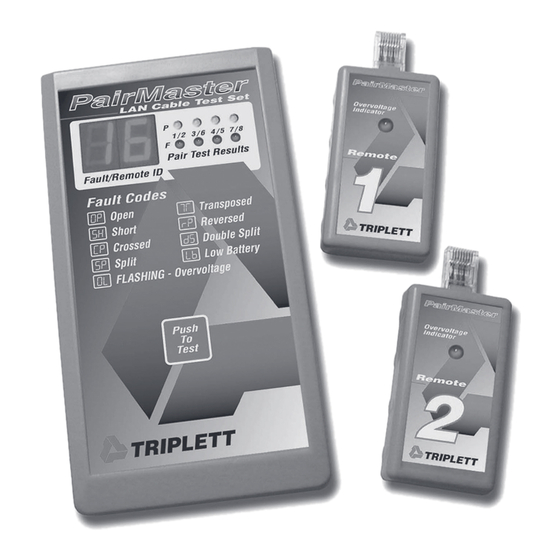
PAIRMASTER OVERVIEW The Triplett PairMaster is an essential test tool for the LAN cable and network installer, maintainer, and technician. It ana- lyzes the LAN cable for faults, performs network mapping, and checks Near End Crosstalk (NEXT). Its Auto Power Off feature extends battery life and its built-in Overload protection prevents damage from crossed phone lines. - Page 6 To Remote Locations Cable Identification – User Diagram Figure 1...
-
Page 7: Features
FEATURES 1) OVERVOLTAGE INDICATOR LED The LED on the Remote Identifier will light up whenever Telco voltages are detected on the cable under test. Example: Connecting the remote to a cable that is energized by a 48 VDC Central Office Battery (a telephone line) will cause the OVERVOLTAGE INDICATOR LED to light up. - Page 8 3) RJ-45 MODULAR JACK This jack is a standard 8-pin modular jack for connecting UTP (Unshielded Twisted Pair) cable to the PairMaster. The jack is keyed so that it can accept either keyed or non-keyed RJ-45 plugs. 4) DIGITAL DISPLAY Under PASS conditions, the display shows the number of the Remote Identifier attached to the cable.
-
Page 10: Operating Instructions
OPERATING INSTRUCTIONS Connect each Remote Identifier into the terminal jack of an office. Observe the OVERVOLTAGE INDICATOR LED on the remote. If the LED is on, Telco voltage is present. Remove the Remote Identifier and investigate the problem. The PairMaster is not intended for use on telephone systems. - Page 11 ** NOTE ** In the event that the PairMaster and the Remote Identifier are both connected to an energized cable, only the PairMaster will give an overvoltage (OL) indication. The OVER- VOLTAGE INDICATOR LED will not light under these conditions. In most situations, the Remote Identifier will be connected to the line first, allowing the user to know immediately if the line is energized.
-
Page 12: Fault Codes
POWER-UP: Displayed immediately after push-to- test (PTT) button is pressed, if everything is normal. LOW BATTERY: Displayed immediately after push-to-test button is pressed if battery voltage is low (less than 6.5 volts). FAULT CODES OVERVOLTAGE: Damaging voltage is present on the cable. The unit will flash “OL “... -
Page 13: Display Faces
Figure 2... - Page 14 A multiple failure on a pair is a condition where more than one fault is present. One example of this is when a pair has one conductor open and the other conductor crossed (short circuited) to another pair (Fig. 3). The first will indicate an open pair and the second will indicate a crossed pair.
-
Page 15: Special Cable Testing
Example of a PairMaster in use Figure 5 The sample display shown above, indicates that the PairMaster is connected to the cable with Remote Identifier #15 attached to the far end. Pair 1/2 is O.K., pair 3/6 has a failure, pair 4/5 is O.K., and pair 7/8 has yet to be tested. -
Page 16: Specifications
Testing two pair Token-Ring cables is similar to testing the Ethernet cables. The difference is that instead of pairs 1/2 and 3/6, the usable readings occur on pairs 3/6 and 4/5. Pairs 1/2 and 7/8 will display (OP), as described on the previous page. Figure 6 SPECIFICATIONS CABLE TYPES: EIA/TIA 568 configuration for UTP Ethernet and... -
Page 17: Accessories
PAIRMASTER (with input protection): Overvoltage conditions are reported by a flashing “OL “on the display. REMOTE IDENTIFIER (with input protection): Overvoltage conditions are reported by the OVERVOLTAGE INDICATOR LED lighting up. * WARNING * Connecting either the PairMaster or the Remote Identifiers to a live power system (110 VAC 60 Hz) will result in permanent damage. -
Page 18: Warranty
Triplett may have, including incidental or consequential damages. - Page 20 TRIPLETT Test Equipment & Tools 850 Perimeter Road, Manchester, NH 03103 PHONE: 800-TRIPLETT FAX: 603-622-2960 www.triplett.com...
Need help?
Do you have a question about the PairMaster 3240-22 and is the answer not in the manual?
Questions and answers