Table of Contents
Advertisement
Quick Links
Advertisement
Table of Contents

Subscribe to Our Youtube Channel
Related Manuals for Triplett MG600


Summary of Contents for Triplett MG600
- Page 1 User Manual MG600 Digital High Voltage Megohmeter/Insulation Tester...
-
Page 2: International Safety Symbols
Introduction Congratulations on your purchase of the Triplett MG600 High Voltage Megohmeter/Insulation Tester. This meter provides four Insulation Resistance test ranges plus Continuity, AC/DC Voltage, Polarization Index and Dielectric Absorption Ratio measurements. Safety International Safety Symbols This symbol, adjacent to another symbol or terminal, indicates the user must refer to the manual for further information. - Page 3 Safety Notes Do not exceed the maximum allowable input range for any of the meter’s functions. Set the function switch OFF when the meter is not in use. Remove the batteries if the meter is to be stored for longer than 60 days. Warnings Set the function switch to the appropriate position before measuring.
- Page 4 If the equipment is used in a manner not specified by the manufacturer, the protection provided by the equipment may be impaired. Do not use the Insulation resistance tester near explosive gas, vapor or dust. When using the test leads, keep fingers away from the lead contacts.
-
Page 5: Meter Description
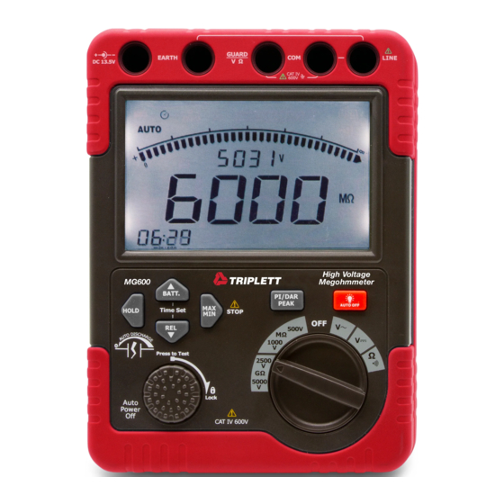
Meter Description Insulation resistance Test/Lock switch REL /down button HOLD button BATT /up button MAX /MIN /STOP button LCD Display DC power adaptor Input EARTH Input VΩ input and IR GUARD terminal 10. VΩ COM input and High voltage shielding terminal 11. -
Page 6: Insulation Resistance Testing
Function Indicator Insulation Resistance Testing CAUTIONS: Ensure that no electrical charge exists on the circuit under test. Insulated gloves should be worn while testing. Use extreme caution to avoid touching the tips of the test leads or the circuit under test when the PRESS TO TEST button is pressed;... -
Page 7: Emergency Stop
Emergency Stop To stop a test at any time, press the STOP button or rotate the PRESS TO TEST knob in a counter-clockwise direction. The STOP button also clears the display and beeper after a discharge is complete. Insulation Resistance Test Manual Test Connect the Black Earth test lead to the... - Page 8 Locked Test Repeat steps 1 to 3 as above. Press and turn the PRESS TO TEST button to the lock position to run the test. The buzzer will beep during the test. Read the measured value on the LCD display. Rotate the PRESS TO TEST button to the PRESS TO TEST position to end the test and discharge the device.
- Page 9 Polarization Index (PI) The polarization index Test calculates the ratio of the resistance measurement after 10 minutes to the resistance measurement after 1 minute: Results are determined by the type, age and condition of the insulation material tested. Established standards and test procedures should be used to establish pass/fail criteria for each application.
- Page 10 Notes: The insulation resistance of a device may not be stable therefore the readings supplied by the meter may vary. An audible beep will be heard while a test is in progress, this is normal. Measurements taken on a capacitive load may take some time to complete.
-
Page 11: Auto Power Off
Data Hold Press the HOLD button to freeze the displayed reading on the LCD display. The HOLD display icon will switch ON in this mode. Press the HOLD button again to return the meter to the normal operation mode. The HOLD display icon will switch OFF. Backlight Press the backlight button to switch on the LCD display backlight. - Page 12 AC/DC Voltage and Resistance Testing AC/DC Voltage Measurements Connect the red test lead to the V terminal and the black test lead to the COM input terminal. Set the Function Selector Switch to the “ ” VAC or the “ ”...
- Page 13 Peak Hold Function (AC/DC Voltage measurements only) The PEAK HOLD function is used with the MAX/MIN function to capture voltage max and min peaks in the range of 10 to 100mS (milliseconds). The voltage range is 0.5V to 600V AC or DC. Press the MAX/MIN button.
-
Page 14: Maintenance
To exit MAX/MIN mode entirely, press and hold the MAX/MIN button for at least 2 seconds. Maintenance Battery Replacement WARNING: To avoid electric shock, disconnect all of the test leads from the unit before replacing the batteries. Operating Caution Do not mix old and new batteries. Make sure the polarity is correct when installing batteries. - Page 15 Power Adaptor The power adaptor input terminal is located at the top left of the tester. Ensure that the meter is powered off before inserting the power adaptor into the input terminal. It is highly recommended that all of the batteries be removed from the meter before using the power adaptor.
-
Page 16: Specifications
Specifications General Specifications Display 6000 count LCD display with bargraph Sampling Rate 2.5 times per second Over range indication "OL" appears on the LCD Short Circuit Current Approx. 1mA Open Circuit Test Voltage > 4.5V Low battery indication Battery symbol appears on the LCD Eight (8) 1.5V ’C’... - Page 17 Insulation Resistance Measurement Specifications Test Voltages 500V 1000V 2500V 5000V * 0.005~6.000MΩ 0.005~6.000MΩ 0.05~60.00MΩ 0.05~60.00MΩ Measurement 6.01~60.00MΩ 6.01~60.00MΩ 60.1~600.0MΩ 60.1~600.0MΩ Range (Auto- 60.1~600.0MΩ 60.1~600.0MΩ 0.61~6.00GΩ 0.61~6.00GΩ ranging) 0.61~6.00GΩ 0.61~6.00GΩ 6.1~60.0GΩ 6.1~60.0GΩ Open circuit DC 500V DC 1000V 2500V DC 5000V +20%,- Voltage +20%,-0%...
-
Page 18: Warranty
Triplett / Jewell Instruments extends the following warranty to the original purchaser of these goods for use. Triplett warrants to the original purchaser for use that the products sold by it will be free from defects in workmanship and material for a period of (1) one year from the date of purchase.
Need help?
Do you have a question about the MG600 and is the answer not in the manual?
Questions and answers