Table of Contents
Advertisement
Quick Links
Advertisement
Table of Contents

Related Manuals for Amroad DP100-25


Summary of Contents for Amroad DP100-25
- Page 2 All Rights Reserved. No part of this publication may be reproduced, transmitted, transcribed, stored in a retrieval system or translated into any language in any form or by any means without the express written permission of Amroad Technology Inc. To obtain consent, write to the attention of Amroad Technology Inc.
-
Page 3: Table Of Contents
CONTENTS Contents ........................................OPYRIGHT CONTENTS ....................................... I CHAPTER 1 : INTRODUCTION ................................1 ........................................1 ELCOME ............................2 ENERAL PPLICATION OF NTRY YSTEM SIP........................................4 SE OF CHAPTER 2 : KNOWING VIDEO DOOR PHONE ........................... 5 ..................................... 5 ACKAGE ONTENTS ........................................ - Page 4 Making Calls From Video Door Phone ................................41 IP V ..............................42 NSWERING ALLS ON IDEO HONE DP100-25 RFID C ..................................43 SAGE Issue Master RFID Card First Time ................................43 Issue a New Card with Master RFID Card..............................43 ......................................44 PEN THE...
- Page 5 CONTENTS Electronic Lock ......................................45 Electronic Bolt ....................................... 45 Wiring Connection and Web Page Setup ..............................46 Electronic Strike ......................................47 Wiring Connection and Web Page Setup ..............................47 APPENDIX B : REGULATORY INFORMATION............................. 49 CE DECLARATION OF CONFORMITY (EUROPE) ..........................50...
-
Page 7: Chapter 1 : Introduction
Welcome Thank you for choosing this Video Door Phone. This DP100-25 is designed to co-work with IP Video Phone to compose a SIP based door entry system. Besides taking advantages of IP technologies, this system also can fully utilize the SIP protocol to link to your SIP VoIP services. -
Page 8: General Application Of Door Entry System
There are two major models of Video Door Phone: one is single unit model, the other is community model. They are applied on different conditions. Please see following descriptions: Villa Application DP100-25 is designed for building, apartment or community. It is also used for single house or villa. Please see Figure 2. - Page 9 DP100-25 VIDEO DOOR PHONE with a large IP PBX. Residents can check visitors, monitor public areas or call each others with extension numbers. Connect to SIP VoIP services via Internet. Figure 3: Community Application Amroad Technology Inc.
-
Page 10: Use Of Sip
DP100-25 SI MANUAL Use of SIP SIP, initial of Session-Initiation-Protocol, it is an application-layer control (signaling) protocol for creating, modifying, and terminating sessions with one or more participants. These sessions include Internet telephone calls, multimedia distribution, and multimedia conferences. Simply say, SIP is a most commonly used protocol that used to interconnect SIP Enabled PBX and/or SIP User... -
Page 11: Chapter 2 : Knowing Video Door Phone
DP100-25 VIDEO DOOR PHONE Chapter 2 : Knowing Video Door Phone Package Contents The following items are included in your Video Door Phone package. Check this list before installation to ensure that you have received all items. Video Door Phone Unit... - Page 12 DP100-25 SI MANUAL Amroad Technology Inc.
-
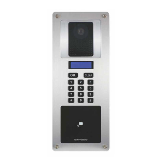
Page 13: Front Panel
DP100-25 VIDEO DOOR PHONE Front Panel Figure 6: Front Panel Amroad Technology Inc. -
Page 14: Led Light
DP100-25 SI MANUAL LED Light There are IR LEDs on both sides of CMOS lens for light compensation. Blue LEDs are behind the keypads, and LCD screen is with blue backlight. The LED and blue backlight will light when any button/keypad is pressed. And, the LED and backlight can be set through WEB UI. -
Page 15: Rear Panel
DP100-25 VIDEO DOOR PHONE Rear Panel Figure 7: Rear Panel and Connectors Amroad Technology Inc. -
Page 16: Reset Button
The default IP type setting of Video Door Phone is “DHCP Client “. 1. Pressing the reset button for 3 seconds=>DP100-25 will turn into Statics IP mode as "192.168.0.50" and reboot by itself. 2. Pressing for over 6 seconds and Green LED ON=>Turn to DHCP mode as the default value and reboot by itself (Restore to factory setting). -
Page 17: Dimensions
DP100-25 VIDEO DOOR PHONE Dimensions Figure 9: Dimensions Amroad Technology Inc. -
Page 18: Chapter 3 : Installing Video Door Phone
DP100-25 SI MANUAL Chapter 3 : Installing Video Door Phone Suggested Installation Positions Due to the view angle of the camera lens is limited, to install the Video Door Phone in a correct position to get better view is very important. Suggested height of the lens position is at the height of 155 cm according to building conditions. -
Page 19: Installing Procedures
DP100-25 VIDEO DOOR PHONE Installing Procedures 1. Insert the Wall Mounting Box into the Wall. Cutting a hole that is able to contain the Wall Mounting Box and prepare the DC +12V and Ethernet cable ready. Then insert the box into the wall and pull the DC wires and Ethernet cable through the hole on the box. You must place the Box very precisely in horizontal in order to keep the Video Door Phone in correct position. -
Page 20: Connect The Dc Wires And Ethernet Cable
2. Connect the DC wires and Ethernet Cable. Connect the DC wire of DP100-25 to H-type power connector, and connect Ethernet cable to DP100-25 according to below Figure 12. Please be careful when you are connecting the DC +12V, be sure to check the DC condition before you start to connect the wires. -
Page 21: Install Video Door Phone Into The Mounting Box
DP100-25 VIDEO DOOR PHONE 3. Install Video Door Phone into the Mounting Box. After properly connecting the wires and cables, insert the Video Door Phone into wall mounting Box carefully. Then screw the 4 screws that come with the package into the front panel. Please double check all the installation procedure again, and you may power on and start the configuration procedures. - Page 22 DP100-25 SI MANUAL NOTE: We suggest that the protective cover should be attached to DP100-25 and should not be torn up after DP100-25 installation. Do not tear up the protective blister until residents of community/building begin to use DP100-25 Video Door Phone.
- Page 23 DP100-25 VIDEO DOOR PHONE Amroad Technology Inc.
-
Page 25: Chapter 4 : Configuring Video Door Phone
DP100-25 VIDEO DOOR PHONE Chapter 4 : Configuring Video Door Phone Finding Video Door Phone on Networks This chapter describes how to configure your Video Door Phone via Web User Interface. Before proceeding IP A d d re s s configuration, you have to locate the Video Door Phone on 10 .3 .1 .7 6... - Page 26 DP100-25 SI MANUAL NOTE:1. While configuring WEB UI (User Interface), please do not operate this product so as to prevent this product from being out of order. 2. Do not input special symbols “, \, and & in the fields on the WEB UI. Otherwise, you will fail to save your setting normally.
-
Page 27: System - Basic Settings
DP100-25 VIDEO DOOR PHONE System - Basic Settings Item Description This ID is a unique number that assigned by Device ID manufacturer. Here shows date and time set on this phone. Date & Time These fields allow user to set correct date and Set New Time time according to the local–standard. - Page 28 This feature allows you to select the display language on the LCD screen. Language Select “English” or “Traditional Chinese” This feature allows you to reboot the DP100-25. When you are pressing “CLEAR” button for 15 Reboot seconds, you get the “Input Password” indicator then input the password and press OK button.
-
Page 29: System - Network Settings
DP100-25 VIDEO DOOR PHONE System – Network Settings Item Description MAC Address This is a quasi-unique identifier attached to most network adapters. IP Type The default value is DHCP Client. There are two options: DHCP Client and Static IP. A. DHCP Client: The system will automatically assign you an IP address. -
Page 30: System Login Name
Login ID and Password. Figure 19: System Login ID Settings System Reboot When user needs to reboot DP100-25 remotely, just click “Reboot” button on this webpage to start this action. After confirm rebooting, Web User Interface will back to the home page, but the video door phone may take 30~60 seconds to restart its system. -
Page 31: Phone Settings - Video
DP100-25 VIDEO DOOR PHONE Phone Settings – Video You may set change the video settings in this page. ITEM Description You may select preferred bandwidth for Bandwidth video and audio streaming. There are 4 options: 128Kbps, 256Kbps, 384Kbps, and 512Kbps. Please check which bandwidth is suitable for you with your service provider. - Page 32 Click this button to save your setting. Save <IMPORTANT>: “Turn on/off IR LED” and “adjust the brightness of CMOS” via Amroad IP Video phone, DP100-25 can’t get the correct value of the CMOS brightness in some environment, please adjust the brightness value via the Amroad IP Video Phone by pressing “2”(brighter) or “8”(darker) in conversation state.
-
Page 33: Phone Settings - Audio
(-23db). (Acceptable value -20~-32) You may enable or disable Voice-Active-Detection function here. The DP100-25 will detect background noise and send silence packet to the other end if this feature is enabled. This allows called parties hear better audio quality. - Page 34 DP100-25 SI MANUAL Amroad Technology Inc.
-
Page 35: Sip Services
You may fill in the password of your SIP service account. For example, 101 Account Password SIP Proxy Server You may select “Enable” to connect other devices in SIP mode. Service NOTE: For Peer-to-Peer mode, both devices (DP100-25 and remote device) need to Amroad Technology Inc. - Page 36 15sec, 30sec, 45sec, or 60sec. Default is 15 seconds. NOTE: The setting is based on your IP PBX. Input the IP address of ICMS. This function is customized and it allows DP100-25 to ICMS send pictures of visitors to ICMS.
-
Page 37: Entrance Settings - Extensions
DP100-25 VIDEO DOOR PHONE Entrance Settings – Extensions You may configure call services in this page: ITEM Description Select “Enable” to allow you use a real house Mapping number instead of extension number Number assigned from IP PBX. For large community, it is easier for visitors to enter the real house numbers than extension numbers. - Page 38 Phone keypad. Where the value is “0” means ‘Notice ticker’ service can be enabled – it indicates “Please Press OK to Operator!” on the LCD screen. When you press OK, DP100-25 will dial the corresponding number. “uri” – This column is the extension number of IP PBX or a Uniform Resource Identifier which is a compact string of characters used to identify or name a resource on the Internet.
- Page 39 After selecting the CSV file, you can press “Upload” button to start the uploading. Export This item allows you to export existing mapping file (*.CSV) from DP100-25. The exported Mapping File mapping file may be a good example for you.
-
Page 40: Entrance Settings - Gpio
(Electronic Strike) - triggered Electronic Door Lock. Press the “#” key a few seconds from your Press “#” to Amroad IP Video Phone or Video Indoor unlock by Station can trigger the function during Figure 25: GPIO Setting answering the phone call. -
Page 41: Entrance Settings -Rfid
DP100-25 VIDEO DOOR PHONE Entrance Settings –RFID You may get the related RFID information and delete the issued RFID Cards here. ITEM Description The master RFID card can issue new Master Card cards for new tenants. This field will display the card number of the Master RFID Card. - Page 42 DP100-25 SI MANUAL The item Erase RFID Number will appear. Then, you may input the specific issued RFID card number to delete it. Amroad Technology Inc.
-
Page 43: Upgrade - Firmware Update
DP100-25 VIDEO DOOR PHONE Upgrade – Firmware Update The Upgrade function allows you to upgrade firmware of the DP100-25. The ways to upgrade the firmware are via Web Item Description This field is to show firmware version number. Hardware Version... - Page 44 DP100-25 SI MANUAL This field displays the version of the RFID Module. RFID Module Version Press the Restore Default button and wait for system to restore its original factory default Restore setting. Factory Default Amroad Technology Inc.
-
Page 45: Configurations
Upload button to start the importing. Figure 28: Configuration You can also use Export File to back up Export File DP100-25 settings on your computer. Press Download button to export, and you are prompted to click “Open” or “Save” for Download NewConfiguration.xml. -
Page 46: Ar Aps
APS (Auto Provision Server). Figure 29: Auto Provision Server Item Description This allows you to upgrade firmware of DP100-25 through network. APS Server: For example, APS Server: https://rc.amroad.com.tw/aps/TaServlet/doorphone.php Click this button to save your setting. -
Page 47: Chapter 5 : Using Video Door Phone
DP100-25 VIDEO DOOR PHONE Chapter 5 : Using Video Door Phone Making Calls From Video Door Phone Welcome! Using the Video Door Phone is quite simple. You will see “Welcome!” on and turn off the LCD display when the system is ready. -
Page 48: Answering Calls On Ip Video Phone
DP100-25 SI MANUAL answered. 5. When call is hang up by receiver, LCD display will show “Hanging Up”. Talking If called extension number is occupied, the bell sounds a busy announcement. 7. If there is no one answering this call, the bell sounds (Ding-Dong) will continuously ring and be discounted automatically after 15 seconds.(The time out can be set at... -
Page 49: Dp100-25 Rfid Card Usage
DP100-25 VIDEO DOOR PHONE DP100-25 RFID Card Usage Residents scan RFID card over the card reader. DP100-25 will verify the database to determine whether to Open door or not. Issue Master RFID Card First Time Take the Master RFID Card from package contents to scan on the DP101R RFID reader after the installation of DP101R is completed. -
Page 50: Open The Door
DP100-25 SI MANUAL The new RFID card is authorized and can be used to scan over DP100-25 card reader and open door. Open the Door With the installation of electronic lock, residents can open the door through the following 3 ways to open door. -
Page 51: Appendix A : Electronic Lock
Electronic Lock The DP100-25 can connect with various Electronic locks, including Electronic Strikes, Electronic Bolts and Electromagnetic locks. There are two types of Electronic door lock applications as below. One is Electronic Bolt, and the other is Electronic Strike. For more Electronic locks, please follow the similar method for connection. -
Page 52: Wiring Connection And Web Page Setup
Wiring Connection and Web Page Setup There are two connectors: Terminal Connector Pack 1 and Terminal Connector Pack 2 on the rear side of the DP100-25. We provide the example for wiring connection and web page setup of Electronic Bolt. -
Page 53: Electronic Strike
Figure 36: Wiring Connection for Electronic Strike Figure 37: Web Page Setup for Electronic Strike When the wire connection is completed, we need to select the “Negative” for Electronic Strike on the GPIO page of Entrance Setting on DP100-25 WEB User Interface Amroad Technology Inc. - Page 54 ELECTRONIC LOCK Amroad Technology Inc.
- Page 55 Amroad Technology Inc.
-
Page 56: Appendix B : Regulatory Information
Note: Combinations of power levels and antennas resulting in a radiated power level of above 100 mW equivalent isotropic radiated power (EIRP) are considered as not compliant with the above mentioned directive and are not allowed for use within the European community and countries that have adopted the European R&TTE directive 1999/5/EC. Amroad Technology Inc. - Page 58 Federal Communication Commission Interference Statement This equipment has been tested and found to comply with the limits for a Class B digital device, pursuant to Part 15 of the FCC Rules. These limits are designed to provide reasonable protection against harmful interference in a residential installation. This equipment generates, uses and can radiate radio frequency energy and, if not installed and used in accordance with the instructions, may cause harmful interference to radio communications.
Need help?
Do you have a question about the DP100-25 and is the answer not in the manual?
Questions and answers