SIGLENT SDS5000X Series User Manual
Digital oscilloscope
Hide thumbs
Also See for SDS5000X Series:
- Service manual (88 pages) ,
- Quick start manual (48 pages) ,
- User manual (270 pages)

Subscribe to Our Youtube Channel
Related Manuals for SIGLENT SDS5000X Series


Summary of Contents for SIGLENT SDS5000X Series
- Page 1 SDS5000X Series Digital Oscilloscope User Manual SDS5000X Series Digital Oscilloscope User Manual UM0105X-E01A W W W . S I G L E N T. C O M 1 / 2 3 6...
-
Page 2: Table Of Contents
SDS5000X Series Digital Oscilloscope User Manual Contents CONTENTS .................................... 2 INTRODUCTION ..............................6 GENERAL SAFETY SUMMARY ........................7 ........................... 7 AFETY ERMS AND YMBOLS ........................... 8 ORKING NVIRONMENT ........................... 9 OOLING EQUIREMENTS AC P ................................ 10 OWER ........................ 11 OWER AND GROUND CONNECTIONS .............................. - Page 3 SDS5000X Series Digital Oscilloscope User Manual 9.10 ............................. 46 NIVERSAL 9.11 .............................. 47 THER UTTONS MULTIPLE APPROACHES TO RECALL FUNCTIONS ............... 48 10.1 ................................ 48 10.2 .............................. 49 ESCRIPTOR 10.3 ...................... 49 HORTCUT UTTON ON THE RONT PANEL QUICKLY CAPTURE THE SIGNAL ......................50 VERTICAL SETUP ............................
- Page 4 SDS5000X Series Digital Oscilloscope User Manual 16.5.1 CAN Signal Settings ..........................125 16.5.2 CAN Trigger ............................126 16.5.3 CAN Serial Decode ..........................126 16.6 LIN T ....................... 128 RIGGER AND ERIAL ECODE 16.6.1 LIN Signal Settings..........................128 16.6.2 LIN Trigger............................129 16.6.3...
- Page 5 SDS5000X Series Digital Oscilloscope User Manual 27.6 I/O S ..............................216 ETTING 27.6.1 LAN ................................ 216 27.6.2 Clock Source............................217 27.7 ..............................217 27.8 ............................218 NSTALL PTIONS 27.9 ........................220 EFERENCE OSITION ETTING 27.10 ..........................223 ERFORM 27.11 .............................. 226 27.12...
-
Page 6: Introduction
Introduction This user manual includes important safety and installation information related to the SDS5000X series oscilloscopes and includes simple tutorials for basic operation of the oscilloscope. W W W . S I G L E N T. C O M... -
Page 7: General Safety Summary
SDS5000X Series Digital Oscilloscope User Manual General Safety Summary This chapter contains information and warnings that must be followed to keep the instrument operating under the appropriate safety conditions. In addition to the safety precautions specified in this section, you must also follow recognized safety procedures. -
Page 8: Working Environment
SDS5000X Series Digital Oscilloscope User Manual 2.2 Working Environment This instrument is intended for indoor use and should be operated in a clean, dry environment with an ambient temperature range of 0 ° C - 50 ° C. Note: Direct sunlight, radiators, and other heat sources should be taken into account when assessing the ambient temperature. -
Page 9: Cooling Requirements
SDS5000X Series Digital Oscilloscope User Manual to equipment measuring terminals that are connected to source circuits in which measures are taken to limit transient voltages to an appropriately low level. Degree of Pollution II refers to a working environment which is dry and non- conductive pollution occurs. -
Page 10: Ac Power
SDS5000X Series Digital Oscilloscope User Manual around the sides of the instrument. CAUTION: Do not block the ventilation holes located on both sides of the scope. CAUTION: Do not allow any foreign matter to enter the scope through the ventilation holes, etc. -
Page 11: Power And Ground Connections
SDS5000X Series Digital Oscilloscope User Manual 2.5 Power and ground connections The instrument includes a grounded cord set containing a molded three- terminal polarized plug and a standard IEC320 (Type C13) connector for making line voltage and safety ground connection. The AC inlet ground terminal is connected directly to the frame of the instrument. -
Page 12: Calibration
SDS5000X Series Digital Oscilloscope User Manual 2.6 Calibration The recommended calibration interval is one year. Calibration should be only performed by qualified personnel. 2.7 Cleaning Clean only the exterior of the instrument, using a damp, soft cloth. Do not use chemicals or abrasive elements. - Page 13 SDS5000X Series Digital Oscilloscope User Manual Warning: Any use of the scope in a manner not specified by the manufacturer may impair the instrument’s safety protection. This instrument should not be directly connected to human subjects or used for patient monitoring.
-
Page 14: First Steps
The oscilloscope has a 3-year warranty (1-year warranty for probe attachments) from the date of shipment, during normal use and operation. SIGLENT can repair or replace any product that is returned to the authorized service center during the warranty period. We must first examine the product to make sure that the defect is caused by the process or material, not by abuse, negligence, accident, abnormal conditions or operation. -
Page 15: Maintenance Agreement
The oscilloscope's firmware has been thoroughly tested and is presumed to be functional. Nevertheless, it is supplied without warranty of any kind covering detailed performance. Products not made by SIGLENT are covered solely by the warranty of the original equipment manufacturer. -
Page 16: Document Conventions
SDS5000X Series Digital Oscilloscope User Manual Document Conventions For convenience, text surrounded by a box border is used to represent the button of the front panel. For example, Print represents the "Print" button on the front panel. Italicsized text with shading is used to represent the touchable or clickable menu/button/region on the touch screen. -
Page 17: Getting Started
SDS5000X Series Digital Oscilloscope User Manual Getting Started 5.1 Power on SDS5000X provides two ways for power on, which are: Power on Line When the “Power on Line” option is enabled, once the oscilloscope is connected to the AC power supply through the power cord, the oscilloscope boots automatically. -
Page 18: System Status
SDS5000X Series Digital Oscilloscope User Manual supply. The only way to fully power down the instrument is to unplug the AC power cord from the outlet. The power cord should be unplugged from the AC outlet if the scope is not to be used for an extended period of time. -
Page 19: Probe
SDS5000X Series Digital Oscilloscope User Manual Probe The SDS5000X series oscilloscope package includes passive probes as standard accessories. Please visit the website at www.siglent.com technical data and ordering information. Probe Compensation When a probe is used for the first time, you should compensate it to match the input channel of the oscilloscope. - Page 20 SDS5000X Series Digital Oscilloscope User Manual Under Perfectly Over Compensated Compensated Compensated 5. Use a non-metallic driver to adjust the low-frequency compensation adjustment hole on the probe until the waveform displayed is as the “Perfectly compensated” in the figure above.
-
Page 21: Quick Start
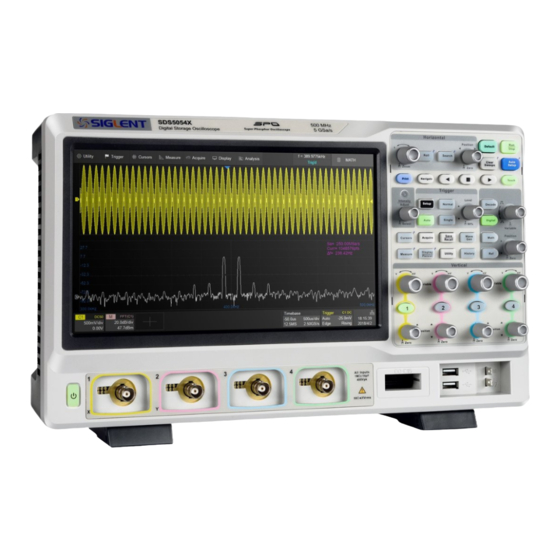
SDS5000X Series Digital Oscilloscope User Manual Quick Start 7.1 Front Panel Overview A. Touch Screen Display: The display and major functions area. See "Touch Screen Display" chapter for more details. B. Front Panel: Includes knobs and buttons. See "Front Panel" chapter for more details. -
Page 22: Rear Panel Overview
SDS5000X Series Digital Oscilloscope User Manual G. Power Switch H. Supporting Legs: Adjust the supporting legs properly to use them as stands to tilt the oscilloscope for stable positioning of the oscilloscope. 7.2 Rear Panel Overview A. Auxiliary Out: Outputs the trigger indicator. When Pass / Fail is enabled, outputs the pass / fail signal. - Page 23 SDS5000X Series Digital Oscilloscope User Manual F. USB Ports: One USB device to connect with a PC for remote control and one USB host to connect with a USB storage device or USB mouse / keyboard. G. AC Power Input H.
-
Page 24: Connecting To External Devices/Systems
SDS5000X Series Digital Oscilloscope User Manual 7.3 Connecting to External Devices/Systems 7.3.1 Power Supply The standard power supply for the instrument is 100~240 V, 50/60 Hz or 100~120 V, 400 Hz. Please use the power cord provided with the instrument to connect it to AC power. -
Page 25: Auxiliary Output
Press the WaveGen button on the front panel or touch the screen Utility AWG Menu to set the waveform. 7.3.7 Probes The SDS5000X series oscilloscope supports active probe and passive probes. The specifications and documents of the probe can be obtained at www.siglent.com. -
Page 26: Logic Probe
SDS5000X Series Digital Oscilloscope User Manual 7.3.8 Logic Probe To connect the logic probe: Insert the probe, with the correct side facing up, until you hear a “click”. To remove the logic probe: Depress the buttons on each side of the probe, then pull out it. -
Page 27: Touch Screen Display
SDS5000X Series Digital Oscilloscope User Manual Touch Screen Display 8.1 Overview The entire SDS5000X display is a capacitive touch screen. Use your fingers to touch, drag, pinch, spread, or draw a selection box. Many controls that display information also work as “buttons” to access other functions. If you using any mouse, you can click anywhere –... -
Page 28: Menu Bar
SDS5000X Series Digital Oscilloscope User Manual F. Trigger Delay Indicator G. Timebase and Trigger descriptor box H. Dialog Box Trigger Level Line (Vertical) and Trigger Delay Indicator (Horizontal) show the trigger position of the waveform. Cursors show where measurement points have been set. Move the cursors to quickly reposition the measurement point. -
Page 29: Grid Area
SDS5000X Series Digital Oscilloscope User Manual Utility>Help Acquire>Sequence Acquire>XY Mode Analysis>Pass/Fail 8.3 Grid Area The grid area displays the waveform traces. Traces can be moved by dragging, and re-scaled by pinch and spread. The area is divided into 8 (vertical) * 10 (horizontal) grids. The best display effect can be obtained by adjusting the waveform intensity and graticule. -
Page 30: Channel Descriptor Box
SDS5000X Series Digital Oscilloscope User Manual Channel Offset Indicator with a channel number shows the offset position of the corresponding channel. 8.4 Channel Descriptor Box A. Channel Index Bandwidth Limit indicator C. Coupling and Input Impedance D. Vertical Scale Vertical Offset... - Page 31 SDS5000X Series Digital Oscilloscope User Manual Coupling and Input Impedance: :DC coupling, 1MΩ impedance :DC coupling, 50Ω impedance :AC coupling, 1MΩ impedance :AC coupling, 50Ω impedance :Ground Vertical Scale: The scale of each grid in the vertical direction. For example, when the vertical scale is 1.00 V/div, the full scale of the oscilloscope is 1.00...
-
Page 32: Timebase And Trigger Descriptor Boxes
SDS5000X Series Digital Oscilloscope User Manual :10:1 attenuation, suitable for general passive probes or active probes with 10X attenuation :100:1 attenuation, suitable for some high-voltage probes :Custom attenuation factor 8.5 Timebase and Trigger Descriptor Boxes A. Trigger delay Horizontal scale (... - Page 33 SDS5000X Series Digital Oscilloscope User Manual A. Trigger source Trigger coupling C. Trigger mode D. Trigger level Trigger type Trigger slope Trigger source C1~C4: Analog channels EXT: External trigger channel EXT/5: 5x attenuation of external trigger channel ...
- Page 34 SDS5000X Series Digital Oscilloscope User Manual on medium to high frequency signals. See the datasheet for details of the cut-off frequency. Trigger mode Auto: The oscilloscope will sweep without a set trigger. An internal timer triggers the sweep after a preset timeout period so that the display refreshes continuously.
-
Page 35: Dialog Box
SDS5000X Series Digital Oscilloscope User Manual 8.6 Dialog Box Dialog box on the right side of the screen is the main area for setting the parameters of the selected function. A. Title bar. Touching the bar can hide the dialog box, and touching again can open the dialog box. - Page 36 SDS5000X Series Digital Oscilloscope User Manual List: Sets parameters with more than two options, such as coupling mode of channels. Touch the parameter region, and then select the expected option from the pop-up list. Virtual Keypad: Sets parameters with numerical value. Touch the parameter region, and the parameter can be adjusted by the universal knob on the front panel;...
-
Page 37: Touch Gestures
SDS5000X Series Digital Oscilloscope User Manual minimum and default values. Hide Dialog Box When the dialog box is opened, the grid area will be compressed horizontally to display the complete waveform. After setting the parameters, in order to achieve the best waveform display effect, you can touch the title bar in the upper right corner to hide the dialog box. - Page 38 SDS5000X Series Digital Oscilloscope User Manual Drag the waveform left and right to move it Pinch and spread the waveform on the horizontal axis horizontally to re-scale the timebase Drag the waveform up and down to move it Pinch and spread the waveform vertically to...
-
Page 39: Mouse And Keyboard Operation
SDS5000X Series Digital Oscilloscope User Manual 8.8 Mouse and Keyboard Operation The SDS5000X user interface features mouse control as well as the touch screen. . If the oscilloscope is connected to a USB mouse, you can click on the object with the mouse instead of touching the object. Similarly, if a USB keyboard is connected, you can use the keyboard to input characters instead of using the virtual keyboard. -
Page 40: Front Panel
SDS5000X Series Digital Oscilloscope User Manual Front Panel 9.1 Overview The front panel is designed to operate the basic functions without having to open the software menu. Most of the front panel controls duplicate functionality available through the touch screen display but the operation is more quickly achieved. -
Page 41: Vertical Control
SDS5000X Series Digital Oscilloscope User Manual 9.2 Vertical Control A. When a channel is disabled, push channel button to turn it on. When the channel is turned on and activated, push the button to disable it. B. Rotate the knob to adjust the DC offset or vertical position of the channel. -
Page 42: Horizontal Control
SDS5000X Series Digital Oscilloscope User Manual 9.3 Horizontal Control A. Rotate to adjust horizontal scale (time/div); push to enable Zoom; push again to exit Zoom mode. B. Rotate to adjust trigger delay; push to set trigger delay to zero. C. Push to enable horizontal Roll; push again to exit Roll mode. At... -
Page 43: Trigger Control
SDS5000X Series Digital Oscilloscope User Manual 9.4 Trigger Control A. Opens trigger setup dialog box B. Single mode: Triggers once when all conditions are met C. Normal mode: Triggers repeatedly when all conditions are met D. Auto mode: Triggers after preset period if no valid trigger occurs E. -
Page 44: Autosetup Button
SDS5000X Series Digital Oscilloscope User Manual 9.6 AutoSetup Button The oscilloscope will automatically set the vertical scale, horizontal scale and trigger level according to the input signal to get optimum waveform display. You can also perform an AutoSetup operation following the steps Trigger ->Auto Setup. -
Page 45: Navigate Control
SDS5000X Series Digital Oscilloscope User Manual dialog box. Press again to turn off math function. D. Press the button to turn on the reference function and open REFERENCE dialog box. Press again to turn off the reference function. E. Rotate the knob to adjust the vertical scale (Volt/div) of Math or Ref. It can also be used to change the selected digital channel. -
Page 46: Cursors Control
SDS5000X Series Digital Oscilloscope User Manual 9.9 Cursors Control A. Push the button to open the cursors setup dialog box B. Rotate the knob to move selected cursor; push to select different cursor 9.10 Universal Knob When the parameter setting area is highlighted, you can use the Universal Knob to adjust or set the parameter. -
Page 47: Other Buttons
SDS5000X Series Digital Oscilloscope User Manual 9.11 Other Buttons Performs a screenshot save to an external storage device. The supported format includes .bmp\.jpg\.png. Clears the data or display in multiple sweeps, including display persistence, measurement statistics, average sweeps and Pass/Fail statistics. -
Page 48: Multiple Approaches To Recall Functions
SDS5000X Series Digital Oscilloscope User Manual 10 Multiple Approaches to Recall Functions The oscilloscope can recall functions through different approaches. 10.1 Menu Bar If you are familiar with common current computer programs, you may first choose to access a function by the drop-down menu from the menu bar at the top of the display. -
Page 49: Descriptor Box
SDS5000X Series Digital Oscilloscope User Manual 10.2 Descriptor Box For setup of channels, math, ref, timebase and trigger, there are dialog boxes at the bottom of the display. For the introduction of the descriptor box, see sections "Channel Descriptor Box" and "Timebase and Trigger Descriptor Box". -
Page 50: Quickly Capture The Signal
SDS5000X Series Digital Oscilloscope User Manual 11 Quickly Capture the Signal This is an example about how to acquire a signal quickly. In this example we assume the signal is connected to channel 1 and channel 1 is turned off. -
Page 51: Vertical Setup
SDS5000X Series Digital Oscilloscope User Manual 12 Vertical Setup 12.1 Turn on/off a Channel From the Front Panel Push the channel button(1-4)to turn on the corresponding channel. Its channel descriptor box and dialog box will appear on the display. Push the same button again to disable the channel. - Page 52 SDS5000X Series Digital Oscilloscope User Manual offset can also be set from this dialog box. A. Touch the region to set the vertical scale with universal knob or virtual keypad B. ▲ to increase the vertical scale and ▼ to decrease C.
- Page 53 SDS5000X Series Digital Oscilloscope User Manual A. Turn channel on/off B. Coupling (DC, AC or GND) C. Bandwidth limit (Full, 200 MHz or 20 MHz) D. Probe attenuation (1X, 10X, 100X or custom) E. Impedance F. Units for the channel G.
- Page 54 SDS5000X Series Digital Oscilloscope User Manual Bandwidth Limit Full bandwidth can pass through signals with high frequency components, but it also means that noise with high frequency components can pass through. When the frequency component of the interested signal is very low, better signal-to-noise ratios (SNR) can be obtained by turning on a bandwidth limit.
- Page 55 SDS5000X Series Digital Oscilloscope User Manual Voltage unit "V" or current unit "A”. When using the current probe, the unit should be set to "A". Deskew Due to the skew between channels, cables or probes, the delay of signals passing through different measurement paths may be inconsistent. For example, two coaxial cables with a 1 inch difference in length could introduce a skew of more than 100 ps.
- Page 56 SDS5000X Series Digital Oscilloscope User Manual When invert is enabled, the waveform is 180 degrees opposite to the earth potential. Before invert After invert W W W. S I G L E N T. C O M 5 6 / 2 3 6...
-
Page 57: Digital Channels
SDS5000X Series Digital Oscilloscope User Manual 13 Digital Channels 13.1 Overview SPL2016 Probe The SPL2016 is a logic probe designed to monitor up to 16 digital signals at once. The 16 digital channels are separated into two groups and each group has its own threshold, making it possible to simultaneously view data from different logic families. - Page 58 The equipment shall be used only for the purposes specified by the manufacturer. The SPL2016 probe is used only for SIGLENT's special series of oscilloscopes. Protection mechanisms can be compromised if the way the devices connected by the SPL2016 are not used for their intended purpose.
-
Page 59: Enable/Disable The Digital Channels
SDS5000X Series Digital Oscilloscope User Manual SDS-5000X-LA16 Option The software option adds the following functions to the oscilloscope: Digital channel acquisition and analysis - Acquire and analyze the signals connected to the digital logic probe, including waveform display, save, parameter measurement, etc. -
Page 60: Digital Channel Setup
SDS5000X Series Digital Oscilloscope User Manual A. Digital channel waveform display, which shares the same grid area with the analog channels. B. Digital channel descriptor box C. Dialog box D. Digital channel indicators. Up to 16 digital channels are organized in two groups with different thresholds: D15~D8 and D7~D0. - Page 61 SDS5000X Series Digital Oscilloscope User Manual A. Upper position limit of the digital channel display area. You can use the universal knob or virtual keypad to set it. Decrease the height to provide more adjustment area. B. ▲ to increase position and ▼ to decrease the channel location.
- Page 62 SDS5000X Series Digital Oscilloscope User Manual The quick menu only covers the height range and position of the digital channels display area. More setting can be found in the dialog box. A. Turn on/off the digital channels B. Labels, can be set to data, address or custom characters.
- Page 63 SDS5000X Series Digital Oscilloscope User Manual The configurable logical level includes TTL, CMOS, LVCMOS 3.3 V, LVCMOS 2.5 V and Custom. The setting range of custom threshold is -10.0 V to + 10.0 W W W. S I G L E N T. C O M...
-
Page 64: Horizontal And Acquisition Setup
SDS5000X Series Digital Oscilloscope User Manual 14 Horizontal and Acquisition Setup 14.1 Timebase Setup The timebase setup is used to adjust the scale and offset of the X (horizontal) axis. This setting applies to all analog, digital channels and all math traces except FFT. -
Page 65: Acquisition Setup
SDS5000X Series Digital Oscilloscope User Manual 14.2 Acquisition Setup 14.2.1 Overview Touch Acquire Menu on the quick menu of the timebase settings, or press the Acquire button on the front panel, or touch the menu bar Acquire>Menu to recall the Acquire dialog box on the right side. - Page 66 SDS5000X Series Digital Oscilloscope User Manual and may be less than memory depth. The actual sample points information can be obtained in the timebase descriptor box (see the section "Timebase and Trigger " for details). The maximum memory depth in single channel mode is 2 times that of the dual...
-
Page 67: Acquisition
SDS5000X Series Digital Oscilloscope User Manual X: Linear interpolation, the simplest way of interpolation, connects two original points with a straight line. Sinc: Sin(x)/x interpolation, the original point is interpolated according to the Nyquist reconstruction formula, which has a good time-domain recovery effect for sine wave. - Page 68 SDS5000X Series Digital Oscilloscope User Manual Peak: Peak detect mode. The oscilloscope acquires the maximum and minimum values of the signal within the sample interval so the peak (maximum – minimum) in the interval is obtained. This mode is effective to observe occasional narrow pulses or spurs with low sample rate, but the noise displayed is larger.
- Page 69 SDS5000X Series Digital Oscilloscope User Manual You can reset the accumulated average by pushing the Clear Sweeps button on the front panel. Normal mode Average mode(32) Note: Average acquisition is only valid for periodic signals, and it is important to ensure that the waveform is triggering in a stable way when using average mode.
- Page 70 SDS5000X Series Digital Oscilloscope User Manual stable triggering, but due to the digital filtering, the system bandwidth of the oscilloscope will degrade in Eres mode. The higher the enhanced bits, the lower the bandwidth. The following table shows the relationship between Eres bits...
-
Page 71: Roll Mode
SDS5000X Series Digital Oscilloscope User Manual 14.2.3 Roll Mode Press the Roll button on the front panel to enter roll mode. In this mode, the waveform moves across the screen from right to left, similar to a strip chart recorder. The horizontal delay control of the waveform will be disabled when roll mode is active. - Page 72 SDS5000X Series Digital Oscilloscope User Manual to a waveform update rate of 500,000 wfm/s. After the acquisition is finished, the oscilloscope will map all the segments together to the screen. If you need to view and analyze each frame separately, history mode will help (see the section "History"...
- Page 73 SDS5000X Series Digital Oscilloscope User Manual Set the coupling mode of C1 to DC50Ω, and vertical scale to 500 mv/div, vertical offset to 0. Set the trigger level to 0. In normal mode, 5 pulses can be obtained on the screen with the sample rate of 1.25GSa/s at the maximum memory depth.
- Page 74 SDS5000X Series Digital Oscilloscope User Manual In Sequence mode, there is no waveform displayed on the screen until the acquisition is completed. During acquisition, there is a counter on the screen indicating the number of segments that have been acquired.
-
Page 75: History
SDS5000X Series Digital Oscilloscope User Manual 14.3 History Press the History button on the front panel or touch Analysis > History to recall history dialog box. A. Turn on or off history mode B. Specify the frame index C. Play backward automatically D. - Page 76 SDS5000X Series Digital Oscilloscope User Manual timebase settings. Turn on history mode, then the stored frames can be recalled and measured. Continue with the example in the section above. In Sequence mode, all waveforms that satisfy the trigger conditions are mapped to the display. If you need to observe a single frame, you can use history mode.
- Page 77 SDS5000X Series Digital Oscilloscope User Manual ms in the following diagram, which is consistent with the period of the actual waveform. Acq Time label Delta T label In addition to manually specifying a frame, history mode supports auto play: Press the softkey to replay the waveform from the current frame to the first.
-
Page 78: Zoom
SDS5000X Series Digital Oscilloscope User Manual 14.4 Zoom The SDS5000X supports waveform zoom in the horizontal direction. Press down the horizontal knob on the front panel to turn on the zoom function. When Zoom function is on, the waveform area is divided into upper and lower parts. - Page 79 SDS5000X Series Digital Oscilloscope User Manual by different gestures, as follows: Adjust the horizontal position of the zoom area by dragging left and right in the zoom area of the main window or waveform in Zoom window Adjust the horizontal position of the waveform by dragging left and right in the gray area...
-
Page 80: Trigger
SDS5000X Series Digital Oscilloscope User Manual 15 Trigger 15.1 Overview The oscilloscope only acquires waveforms of interest (i.e. the ones that satisfy the trigger condition) and aligns all trigger events at the trigger position to form a stable waveform display. The trigger is one of the most important features of any oscilloscope, since we can only analyze a signal that we are able to trigger in a reliable and stable manner. -
Page 81: Trigger Setup
SDS5000X Series Digital Oscilloscope User Manual Ready: The pre-trigger buffer is full, and the oscilloscope is waiting for the trigger event. Trig’d: A trigger event is detected and the oscilloscope starts to fill the post- trigger buffer. Trigger settings should be based on the features of the input signal. For example, a sine wave with repeatable period can be triggered on the rising edge;... - Page 82 SDS5000X Series Digital Oscilloscope User Manual button on the front panel E. Set the trigger mode to "Single", which is equivalent to pressing the Single button on the front panel F. Set the trigger mode to "Normal", which is equivalent to pressing the Normal button on the front panel A.
-
Page 83: Trigger Level
SDS5000X Series Digital Oscilloscope User Manual Trigger level Indicator Horizontal 0 position Horizontal 0 position(out of Indicator screen) Indicator 15.3 Trigger Level Both analog and digital triggers must have a correct trigger level value. The oscilloscope judges whether a waveform satisfies the trigger condition when it crosses the trigger level. -
Page 84: Trigger Mode
SDS5000X Series Digital Oscilloscope User Manual 15.4 Trigger Mode The trigger mode determines how the oscilloscope acquires waveforms. Auto:An internal timer triggers the sweep after a preset timeout period if no trigger has been found, so that the oscilloscope continuously updates the display whether a trigger happens or not. -
Page 85: Trigger Type
SDS5000X Series Digital Oscilloscope User Manual 15.5 Trigger Type 15.5.1 Overview The trigger modes of the SDS5000X are digital designs. Compared with analog trigger circuits, digital triggers can not only greatly optimize trigger precision, trigger jitter, but also support multiple trigger types and complex trigger conditions. - Page 86 SDS5000X Series Digital Oscilloscope User Manual W W W. S I G L E N T. C O M 8 6 / 2 3 6...
-
Page 87: Edge Trigger
SDS5000X Series Digital Oscilloscope User Manual 15.5.2 Edge Trigger Edge trigger distinguishes the trigger points by seeking the specified edge (rising, falling, rising & falling) and trigger level. Trigger source and slope can be set in the trigger dialog box. - Page 88 SDS5000X Series Digital Oscilloscope User Manual with the positive edge as shown in the figure below. Touch the Source area to select trigger source, and touch the Slope area to select rising or falling. Rising -- Only trigger on the positive slope...
- Page 89 SDS5000X Series Digital Oscilloscope User Manual Press the knob to switch between upper and lower level, and rotate it to set the value. The lower level should always be less than or equal to the upper level. In the trigger descriptor box, the lower level is displayed.
-
Page 90: Pulse Trigger
SDS5000X Series Digital Oscilloscope User Manual 15.5.4 Pulse Trigger Trigger on a positive or negative pulse with a specified width. Trigger source, polarity (positive, negative), limit range and time value can be set in the trigger dialog box. Less than a time value(≤)-- Trigger when the positive or negative pulse time of the input signal is lower than the specified time value. -
Page 91: Video Trigger
SDS5000X Series Digital Oscilloscope User Manual Outside a range of time value(--][--)-- trigger when the positive or negative pulse time of the input signal is greater than the specified upper limit of time and lower than the specified lower limit of the time value. - Page 92 SDS5000X Series Digital Oscilloscope User Manual TV Standard Scan Type Sync Pulse NTSC Interlaced Bi-level Interlaced Bi-level HDTV 720P/50 Progressive Tri-level HDTV 720P/60 Progressive Tri-level HDTV 1080P/50 Progressive Tri-level HDTV 1080P/60 Progressive Tri-level HDTV 1080i/50 Interlaced Tri-level HDTV 1080i/60 Interlaced...
- Page 93 SDS5000X Series Digital Oscilloscope User Manual Lines" is set to 800, the correct relationship between them is as follows: Of Lines Interlace Of Fields Trigger Line Trigger Field 1/2/4/8 1/1~2/1~4/1~8 1/2/4/8 1/1~2/1~4/1~8 1/2/4/8 1/1~2/1~4/1~8 Set the video trigger for video signal Touch Sync for trigger mode selection, video trigger mode has "Any"...
- Page 94 SDS5000X Series Digital Oscilloscope User Manual 1 to 313 1 to 312 HDTV 720P/50、720P/60 1 to 750 HDTV 1080P/50、1080P/60 1 to 1125 HDTV 1080i/50、1080i/60 1 to 563 1 to 562 To gain familiarization with the video trigger, try these two examples: ...
- Page 95 SDS5000X Series Digital Oscilloscope User Manual Trigger on a Specific Line of Video (NTSC) Use "Custom" to Trigger Video Signals Custom video trigger supports video signals with frame rates of 25, 30, 50 and 60 Hz respectively, and the specified row is within the range of 300 to 2000.
-
Page 96: Window Trigger
SDS5000X Series Digital Oscilloscope User Manual b) Select the "Select" mode, then set the specified line and the specified field to trigger the signal. Assuming that the "Field" is set to 8, you can select any field from 1 to 8, and each field can choose any line from 1 to 100. - Page 97 SDS5000X Series Digital Oscilloscope User Manual If the upper trigger level is within the waveform amplitude range while the lower trigger level is out of the waveform amplitude range, the oscilloscope will trigger on the rising edge only. ...
-
Page 98: Interval Trigger
SDS5000X Series Digital Oscilloscope User Manual Note: "Level +/-Delta” represents half of the actual window area. For example, when the value is 200 mV, it actually represents a range of ± 200 mV, which is a 400 mV window. Coupling and noise reject can be set when using the window trigger, see the sections "Coupling”, “Noise"... - Page 99 SDS5000X Series Digital Oscilloscope User Manual Edge Trigger when the time interval (△T) from when the rising edge (or falling edge) of the input signal passes through the trigger level to when the neighboring rising edge (or falling edge) passes through the trigger level is greater than the...
-
Page 100: Runt Trigger
SDS5000X Series Digital Oscilloscope User Manual 15.5.9 Runt Trigger Runt trigger looks for pulses that cross one threshold but not another as shown in the figure below: A positive runt pulse across through the low level but not the high level. -
Page 101: Pattern Trigger
SDS5000X Series Digital Oscilloscope User Manual 15.5.10 Pattern Trigger The Pattern trigger identifies a trigger condition by looking for a specified pattern. The SDS5000X provides 4 patterns: logical AND, OR, NAND and NOR combination of the channels. Each channel can set to "Low", "High" or "Don't Care". -
Page 102: Qualified Trigger
SDS5000X Series Digital Oscilloscope User Manual Logical setting of analog channel Logical setting of digital channel Limit Range When the logic is "AND" or "NOR", the time limit condition is available. This setting is particularly useful to filter the hazard signals of combinational logic. - Page 103 SDS5000X Series Digital Oscilloscope User Manual Qualified Source Edge Trigger Source Trigger Qualified State = High Edge = Rising Position When the type is “Edge”, the oscilloscope triggers at the first edge after the specified edge (Rising or Falling) of the qualified source; when the type is “Edge with Delay”, time limit condition is available.
-
Page 104: Trigger Source
SDS5000X Series Digital Oscilloscope User Manual 15.6 Trigger Source The trigger sources supported by each trigger type are different. See the table below for details: Trigger Type C1~C4 EXT, EXT/5 AC Line D0~D15 √ √ √ √ Edge √ ×... -
Page 105: Holdoff
SDS5000X Series Digital Oscilloscope User Manual 15.7 Holdoff Holdoff is an additional condition for triggers and can be used to stabilize the triggering of complex waveforms (such as a pulse series). It can be set to a time or number of events. - Page 106 SDS5000X Series Digital Oscilloscope User Manual Parameter Start Holdoff On defines the initial position of holdoff. Acq Start -- The initial position of holdoff is the first time point satisfying the trigger condition. In the example above, each holdoff starts from the first rising edge of the pulse sequence.
-
Page 107: Trigger Coupling
SDS5000X Series Digital Oscilloscope User Manual 15.8 Trigger Coupling The coupling setting of trigger is only valid when the trigger source is C1~C4, EXT or EXT/5. DC: All of the signal’s frequency components are coupled to the trigger circuit for high frequency bursts or where the use of AC coupling would shift the effective trigger level. - Page 108 SDS5000X Series Digital Oscilloscope User Manual Noise Reject = Off Noise Reject = On W W W. S I G L E N T. C O M 1 0 8 / 2 3 6...
-
Page 109: Serial Trigger And Decode
SDS5000X Series Digital Oscilloscope User Manual 16 Serial Trigger and Decode 16.1 Overview The SDS5000X supports serial bus trigger and decode on the following serial bus protocols: I2C, SPI, UART, CAN, and LIN. Press the Setup button on the front panel or touch the trigger descriptor box, and then select the Type as Serial in the trigger dialog box to set serial trigger: A. -
Page 110: I2C Trigger And Serial Decode
SDS5000X Series Digital Oscilloscope User Manual A. Turn on/off serial decode function B. Select the bus to set, Decode1 and Decode2 C. Select the serial bus protocol D. Touch to set the signal, including the mapping relation between channels and bus signals, and the thresholds. -
Page 111: I2C Signal Settings
SDS5000X Series Digital Oscilloscope User Manual 16.2 I2C Trigger and Serial Decode This section covers triggering and decoding I2C signals. Please read the following for more details: "I2C Signal Settings", "I2C Trigger" and "I2C Serial Decode". 16.2.1 I2C Signal Settings... -
Page 112: I2C Trigger
SDS5000X Series Digital Oscilloscope User Manual E. Return to previous menu. F. Threshold level line. It only appears when adjusting the threshold level. Copy Setting Touch the Copy Setting in the decode dialog box to synchronize the settings between trigger and decode. - Page 113 SDS5000X Series Digital Oscilloscope User Manual Touch Trigger Setting in the I2C trigger dialog box to select the trigger condition: Start — The oscilloscope will be triggered when the SDA line transitions from high to low while the SCL is high.
- Page 114 SDS5000X Series Digital Oscilloscope User Manual EEPROM — The trigger searches for EEPROM control byte value 1010xxx on the SDA bus. And there is a Read bit and an ACK bit behind EEPROM. Set the data value and compare type according to Data1 and Limit Range.
- Page 115 SDS5000X Series Digital Oscilloscope User Manual 10 Address&Data — If all bits match, then trigger on the Ack bit followed by the Data. Frame (Start: Address 1st byte: R/W: Ack: Address 2nd byte: Ack: Data) W W W. S I G L E N T. C O M...
- Page 116 SDS5000X Series Digital Oscilloscope User Manual If you set the trigger condition to 7 address&data or 10 address&data: Address can be selected in the hexadecimal range of 0x00 to 0x7F (7-bit) or 0x3FF (10-bit). If the address is selected as "0xXX (7-bit address)"...
-
Page 117: I2C Serial Decode
SDS5000X Series Digital Oscilloscope User Manual 16.2.3 I2C Serial Decode Layout of the touchscreen display when I2C decode enabled is as follows: A. Waveform display area, shows the original waveforms of the bus signals B. Bus display, shows the decode result of the bus. At most two buses can be decoded at the same time. -
Page 118: Contents
SDS5000X Series Digital Oscilloscope User Manual The address value is displayed at the beginning of a frame. The write address is displayed in green, and read address in yellow. W/R bit is represented by (W) and (R), following the address value. - Page 119 SDS5000X Series Digital Oscilloscope User Manual Configuration There is only one item Include R/W Bit in the configuration of the I2C decode. When it is disabled, the address is represented separately from the R/W bit, and when it is enabled, the R/W bit is represented together with the address.
-
Page 120: Spi Trigger And Serial Decode
SDS5000X Series Digital Oscilloscope User Manual 16.3 SPI Trigger and Serial Decode The following sections describe SPI trigger and decode: "SPI Signal Settings", "SPI Trigger" and "SPI Serial Decode". 16.3.1 SPI Signal Settings Connect the CLK, MOSI, MISO and CS signals to the oscilloscope and set the mapping relation between channels and signals. - Page 121 SDS5000X Series Digital Oscilloscope User Manual The CS signal should be set to correct CS Type, including CS, ~CS and Clock Timeout. CS – Active high. ~CS – Active low. Clock Timeout– It is not necessary to specify the source and threshold level for the CS signal.
-
Page 122: Spi Trigger
SDS5000X Series Digital Oscilloscope User Manual 16.3.2 SPI Trigger The trigger condition for SPI trigger is mainly about data. Touch Trigger Setting in the dialog box to set data: A. Trigger Type: MISO or MOSI B. Data Length: 4~96 bits C. -
Page 123: Uart Trigger And Serial Decode
SDS5000X Series Digital Oscilloscope User Manual 16.4 UART Trigger and Serial Decode The following sections cover trigger and decoding UART signals: "UART Signal Settings", "UART Trigger" and "UART Serial Decode". 16.4.1 UART Signal Settings Connect the RX and TX signals to the oscilloscope, set the mapping relation between channels and signals, and then set the threshold level of each signal. -
Page 124: Uart Trigger
SDS5000X Series Digital Oscilloscope User Manual A. Touch select baud rate: 600,1200,2400,4800,9600,19200,38400,5760 0,115200 or Custom B. Data Length: 5~8bit C. Parity Check: Odd Even or None D. Select the number of stop bits E. Set the idle level F. Set the bit order G. -
Page 125: Uart Serial Decode
SDS5000X Series Digital Oscilloscope User Manual A. Source Type: RX or TX B. Trigger Condition: Start, Stop, Data or Error C. When the "trigger condition" is Data, set the compare type to: =, >, < D. When the "trigger condition" is Data, set the data value E. -
Page 126: Can Trigger And Serial Decode
SDS5000X Series Digital Oscilloscope User Manual 16.5 CAN Trigger and Serial Decode The following section covers triggering and decoding CAN signals: "CAN Signal Settings", "CAN Trigger" and "CAN Serial Decode". 16.5.1 CAN Signal Settings Connect the CAN_H and CAN_L signals to the oscilloscope, set the mapping relation between channels and signals, and then set the threshold level of each signal. -
Page 127: Can Trigger
SDS5000X Series Digital Oscilloscope User Manual 16.5.2 CAN Trigger Touch Trigger Setting in the CAN trigger dialog box to set the trigger condition: Start — The oscilloscope triggers at the beginning of the frame. Remote — The oscilloscope triggers on a remote frame with a specified ... - Page 128 SDS5000X Series Digital Oscilloscope User Manual ID, LEN (data length), DATA and CRC are all displayed in white. indicates there is not enough space on the display to show complete content of a frame and some content is hidden.
-
Page 129: Lin Trigger And Serial Decode
SDS5000X Series Digital Oscilloscope User Manual 16.6 LIN Trigger and Serial Decode Please trigger and decode the LIN signals in the order of "LIN Signal Settings", "LIN Trigger" and "LIN Serial Decode". 16.6.1 LIN Signal Settings Connect the LIN signals to the oscilloscope, set correctly the mapping relation between channels and signals, and then set the threshold level of each signal. -
Page 130: Lin Trigger
SDS5000X Series Digital Oscilloscope User Manual 16.6.2 LIN Trigger Touch Trigger Setting in the LIN trigger dialog box to set the trigger conditions: Break — The oscilloscope triggers at the beginning of the frame. ID — The oscilloscope triggers on the frame that matches the specified ID, ... - Page 131 SDS5000X Series Digital Oscilloscope User Manual In the list: Time — The horizontal offset of the current data frame head relative to the trigger position. ID — ID of the frame. Data length — Data length. ID Parity — ID parity check.
-
Page 132: Cursors
SDS5000X Series Digital Oscilloscope User Manual 17 Cursors 17.1 Overview Cursors are important tools when measuring signals. Rapid measurements can be performed using cursors in both horizontal and vertical directions. The cursor types includes X1, X2, X1-X2, Y1, Y2 and Y1-Y2, used to indicate X-axis values (time or frequency) and Y-axis values (amplitude) on a selected waveform (CH1/CH2/CH3/CH4/MATH/REFA/REFB/REFC/REFD). - Page 133 SDS5000X Series Digital Oscilloscope User Manual A. Turn on or off cursors function B. Cursors Mode. The vertical cursors will automatically track the waveform in Trace mode. C. Specify the cursor and set the position (by gestures, universal knob, or virtual keypad) D.
- Page 134 SDS5000X Series Digital Oscilloscope User Manual Manual Mode Track Mode W W W. S I G L E N T. C O M 1 3 4 / 2 3 6...
- Page 135 SDS5000X Series Digital Oscilloscope User Manual Cursors Type X (horizontal) -- Vertical dotted lines that measure horizontal time (when the source is an FFT waveform, X cursors measure frequency). X cursors (time) X cursors (frequency) X1 — The left (default) vertical dotted line. It can be manually moved to any horizontal position on the screen.
- Page 136 SDS5000X Series Digital Oscilloscope User Manual Y1 — The upper (default) horizontal dotted line. It can be manually moved to any vertical position on the screen. Y2 — The lower (default) horizontal dotted line. It can be manually moved to any vertical position on the screen.
-
Page 137: Select And Move Cursors
SDS5000X Series Digital Oscilloscope User Manual Display Mode Display Mode M1 Display Mode M2 M1 – The position information of each cursor is attached to the cursor, and the difference information is between the two cursors with arrows connected to the cursors. This mode is more intuitive. - Page 138 SDS5000X Series Digital Oscilloscope User Manual Touch the display area of △X (or△Y) in M1 mode and drag it to move the two cursors simultaneously, as shown in the figure below. This is equivalent to the operation on the cursor type X1-X2 or Y1-Y2.
- Page 139 SDS5000X Series Digital Oscilloscope User Manual Gestures move the cursor quickly but not precisely, while the knob moves the cursor precisely but not as quickly. You can use both in combination to suit your needs: First, a rough adjustment is achieved by using gestures and then fine adjustment is achieved by using the universal knob.
-
Page 140: Measurement
SDS5000X Series Digital Oscilloscope User Manual 18 Measurement 18.1 Overview The SDS5000X features a strong automatic measurement list. These parameters can be automatically measured without cursors. Included are common measurements such as rise time, fall time, peak-peak, and period. The SDS5000X can also measure multiple channels at the same time, showing up to 5 parameter measurements with and statistics at one time. - Page 141 SDS5000X Series Digital Oscilloscope User Manual A. Waveform display area, automatically compresses when the other windows are displayed B. “All Meas” parameter display area C. Measurement parameters and statistics display area D. Measure dialog box Press the Measure button on the front panel or touch Measure>Menu to open the dialog box.
-
Page 142: Set Parameters
SDS5000X Series Digital Oscilloscope User Manual A. Turn on or off measure B. Turn on or off the statistics C. Turn on or off all measure. It will show all measurements of the specified channel. D. Select the source of the measurement E. - Page 143 SDS5000X Series Digital Oscilloscope User Manual A. Indicates the source of the current setting. B. Measurement parameter classification tabs, including vertical measurement, horizontal measurement and channel delay (CH Delay) measurement. Touch a tab and in the area will display the corresponding parameters C.
- Page 144 SDS5000X Series Digital Oscilloscope User Manual For the channel delay (CH Delay) measurement, because the number of sources involved is greater than 1, the steps to specify the source is different: In the parameter selection area, the channel corresponding to Source A is specified first, and then the channel corresponding to Source B.
-
Page 145: Type Of Measurement
SDS5000X Series Digital Oscilloscope User Manual 18.3 Type of Measurement 18.3.1 Vertical Measurement Vertical measurement includes 17 parameters: Max: Highest value in the input waveform Min: Lowest value in the input waveform Pk-Pk: Difference between maximum and minimum data values ... - Page 146 SDS5000X Series Digital Oscilloscope User Manual Stdev: Standard deviation of the data Cycle Stdev: Standard deviation of the data in the first cycle RMS: Root mean square of the data Cycle RMS: Root mean square of the data in the first cycle ...
-
Page 147: Horizontal Measurement
SDS5000X Series Digital Oscilloscope User Manual L@T: Level measured at trigger position 18.3.2 Horizontal Measurement Horizontal measurement includes 11 parameters: W W W. S I G L E N T. C O M 1 4 7 / 2 3 6... -
Page 148: Delay Measurement
SDS5000X Series Digital Oscilloscope User Manual Period: Time between the middle threshold points of two consecutive like-polarity edges. Freq: Reciprocal of period +Width: Time difference between the 50% threshold of a rising edge to the 50% threshold of the next falling edge of the pulse ... - Page 149 SDS5000X Series Digital Oscilloscope User Manual Phase: Phase difference between two edges FRFR:The time between the first rising edge of source A and the following first rising edge of source B at the 50% crossing FRFF:The time between the first rising edge of source A and the following first falling edge of source B at the 50% crossing ...
-
Page 150: Measurement Statistics
SDS5000X Series Digital Oscilloscope User Manual 18.4 Measurement Statistics Enable the Statistics function to observe distribution of the measured values of every selected parameter. Value – The current measurement Mean – Average of all historical measurements Min – The minimum of all historical measurements Max –... -
Page 151: All Measurement
SDS5000X Series Digital Oscilloscope User Manual 18.5 All Measurement Enabling All Measurement displays all vertical and horizontal measurement parameters of the specified channel at the same. The font color of the measurement parameters is consistent with the color of the specified source. - Page 152 SDS5000X Series Digital Oscilloscope User Manual The figure below shows a scenario in which the gate function is used to measure the peak-peak parameter of the trough of an amplitude modulated waveform: W W W. S I G L E N T. C O M...
-
Page 153: Math
SDS5000X Series Digital Oscilloscope User Manual 19 Math 19.1 Overview The SDS5000X supports multiple math operations on the analog channels, including addition (+), subtraction (-), multiplication (x), division (/), FFT, differential (d/dt), integral (∫dt), square root (√) and FFT. The math trace is displayed in white and labeled with an “M”... - Page 154 SDS5000X Series Digital Oscilloscope User Manual A. Turn on or off math operation B. Select the operation C. Select the source. The number of sources corresponding to different operators is different. Addition, subtraction, multiplication division have sources, while others have only one.
-
Page 155: Addition/Subtraction/Multiplication/Division
SDS5000X Series Digital Oscilloscope User Manual ∫dt VS (Volt*Second)0 or AS (A*Second) ∧ ∧ √ 0.5 or A 19.2 Addition/Subtraction/Multiplication/Division The SDS5000X can perform arithmetic operations including addition, subtraction, multiplication or division on any two analog input channels. The values of Source A and Source B are computed point-by-point. - Page 156 SDS5000X Series Digital Oscilloscope User Manual y(i) di Where: d = Differential result y = Values of source data i = Data point index dx = Differential interval The range of “dx” in the d/dt menu is1~20. The measurement units are point and the corresponding time difference range is 0.01~0.20 div.
-
Page 157: Integral
SDS5000X Series Digital Oscilloscope User Manual to “Average” or “Eres” to help minimize the visible effects of additional noise. 19.4 Integral Integral operation integrates the waveforms on the screen or within the specified gate. Setting Offset in the integral menu provides an approach to correct the DC offset of the source. - Page 158 SDS5000X Series Digital Oscilloscope User Manual W W W. S I G L E N T. C O M 1 5 8 / 2 3 6...
-
Page 159: Square Root
SDS5000X Series Digital Oscilloscope User Manual 19.5 Square Root Square root (√) calculates the square root of selected source. If the waveform value is negative (the waveform is below the ground level), the result is displayed as zero. W W W. S I G L E N T. C O M... -
Page 160: Fft
SDS5000X Series Digital Oscilloscope User Manual 19.6 FFT The result of FFT (Fast Fourier Transform) calculations is the frequency spectrum of the source signal. The horizontal axis of the FFT display is labeled using frequency (Hz) units instead of time (second). In addition, the vertical axis provides the option of logarithmic scaling (dBVrms/dBArms or dBm). - Page 161 SDS5000X Series Digital Oscilloscope User Manual FFT sample rate (Sa): FFT operation results present the first Nyquist zone (DC ~ Sa/2) of the frequency spectrum. Be aware that the FFT sample rate may be inconsistent with the sample rate in the time domain.
- Page 162 SDS5000X Series Digital Oscilloscope User Manual Select Operation as FFT in the math dialog box and set the parameters of FFT: A. Set the window type (Rectangle, Blackman, Hanning, Hamming and Flattop) B. Select the display mode (Split, Full Screen and Exclusive) C.
- Page 163 SDS5000X Series Digital Oscilloscope User Manual Windows Spectral leakage in FFT can be considerably decreased when a window is used. SDS5000X provides five windows which have different characteristics and are applicable to different scenarios. For example, for a two-tone signal with very close frequency interval, it is suitable to use Rectangle window with the best frequency resolution.
- Page 164 SDS5000X Series Digital Oscilloscope User Manual Window Characteristics Main lobe Side lobe Maximum width suppression amplitude error The best amplitude resolution Display Mode Split: Time domain waveform and frequency domain waveform are displayed separately. The time domain waveform is on the upper half screen, while the frequency domain waveform is located within the lower half of the display.
- Page 165 SDS5000X Series Digital Oscilloscope User Manual Normal: Displays the FFT result of each frame directly. Max-Hold: Holds the maximum value in the historic frame on the display. This mode is suitable for detecting discontinuous waves, such as sporadic pulse signals, or frequency hopping signals.
- Page 166 SDS5000X Series Digital Oscilloscope User Manual scaling is the reference level. Horizontal Control Touch Center Freq to set the center frequency of FFT waveform by the universal knob or the virtual keypad. Touch Hz/div to set the horizontal scale of FFT waveform by the universal knob or the virtual keypad.
-
Page 167: Reference
SDS5000X Series Digital Oscilloscope User Manual 20 Reference Data from analog channels or math can be saved to the reference locations (REFA/REFB/REFC/REFD) in the built-in nonvolatile memory. The saved reference waveform can be recalled to be compared with current waveform. - Page 168 SDS5000X Series Digital Oscilloscope User Manual A. Select the location of the reference (REFA/REFB/REFC/REFD) B. Select the source (C1~C4 and MATH) C. Enable/disable Display of the reference waveform D. Save the specified waveform in to the specified location in Adjust the Reference Waveform...
-
Page 169: Search
SDS5000X Series Digital Oscilloscope User Manual 21 Search The SDS5000X can search for the specified events in a frame. Location of the events are displayed with white triangle indicators. In YT mode or Roll mode with the acquisition stopped, up to 1000 events is supported. In Roll mode with acquisition in run, the number of search events is unlimited. - Page 170 SDS5000X Series Digital Oscilloscope User Manual Press the Search button on the front panel or touch the menu Analysis>Search to recall the search dialog box and turn on it. Setup Menu Select and set the search type in the Setup Menu. The SDS5000X provides five search conditions: Edge, Slope, Pulse, Interval and Runt.
- Page 171 SDS5000X Series Digital Oscilloscope User Manual Limit Range setting is available Pulse Polarity: Positive, Negative Limit Range setting is available Interval Slope: Rising, Falling Limit Range setting is available Runt Polarity: Positive, Negative Limit Range setting is available Search setup is similar to the corresponding trigger type. See the sections “Edge Trigger”, “Slope Trigger”, ”Pulse Trigger”, ”Interval Trigger”...
-
Page 172: Navigate
SDS5000X Series Digital Oscilloscope User Manual 22 Navigate Press the Navigate button on the front panel or touch the menu Analysis>Navigate to recall the navigate dialog box. The SDS5000X provides three navigate types: Search Event, Time and History Frame. Navigate by Time... - Page 173 SDS5000X Series Digital Oscilloscope User Manual Navigate by Search Event When the Search function is turned on and the acquisition is stopped, Navigate is usable to find search events (see the chapter "Search" for search function). Touch Type in the navigate dialog box to select the navigate type as “Search Event”.
- Page 174 SDS5000X Series Digital Oscilloscope User Manual W W W. S I G L E N T. C O M 1 7 4 / 2 3 6...
- Page 175 SDS5000X Series Digital Oscilloscope User Manual Navigate by History Frame When the history function is turned on, Navigate can be used to play history frames (see the chapter "History" for details of history function). Touch Type in the navigate dialog box to select the navigate type as “History Frame”.
- Page 176 SDS5000X Series Digital Oscilloscope User Manual First, set the trigger type to Runt to trigger on the dwarf pulse. See the section “Runt Trigger” for details. Then turn on Search function and operate Copy from Trigger in the search dialog box so that the oscilloscope searches for the dwarf pulses according to the same setting as the trigger.
- Page 177 SDS5000X Series Digital Oscilloscope User Manual Turn on Zoom function to observe the full view of the frame and the detail of the third dwarf pulse at the same time: Press the Run/Stop button on the front panel to stop the acquisition, and then follow the steps Navigate>Type to select “Search Event”.
- Page 178 SDS5000X Series Digital Oscilloscope User Manual shows the first dwarf pulse. In this example the list is enabled and time labels of each event are shown in the list. W W W. S I G L E N T. C O M...
-
Page 179: Pass/Fail
SDS5000X Series Digital Oscilloscope User Manual 23 Pass/Fail 23.1 Overview Users can create masks and define the rule used to evaluate Pass/Fail operations. An event violating the rule is defined as a failure and a pulse can be generated from the "Aux Out" port on the back panel. This is very useful to find and quantify anomalies in production tests or similar batch measurements. - Page 180 SDS5000X Series Digital Oscilloscope User Manual Perform Analysis>Pass/Fail to open the Pass/Fail dialog box: A. Turn on/off the test B. Select the source(C1~C4) C. Select the rule(All In, All Out, Any In and Any Out) D. Turn on/off the Pass/Fail operation.
-
Page 181: Mask Setup
SDS5000X Series Digital Oscilloscope User Manual 23.2 Mask Setup Touch Mask Setup in the Pass/Fail dialog box to set the mask: A. Create mask automatically according to the waveform B. Create custom mask using the Mask Editor tool C. Specify the location of the mask to be loaded D. -
Page 182: Create Mask
SDS5000X Series Digital Oscilloscope User Manual 23.2.1 Create Mask The mask can be created based on an existed waveform trace. A. Set the spacing of the mask to the trace in horizontal, with unit of division B. Set the spacing of the mask to the trace in vertical, with unit of division C. - Page 183 SDS5000X Series Digital Oscilloscope User Manual X=0.2 div, Y=0.2 div X=1 div, Y=1 div Saving and recalling mask files (*.msk) is similar to the operation of setup files, see the chapter "Save/Recall" for details. Only one mask file is supported to save when the location is "Internal".
-
Page 184: Mask Editor
SDS5000X Series Digital Oscilloscope User Manual virtual keypad and then touch the “Input” button the perform the ordinate update F. Display or hide coordinate of polygon vertices on the display G. Exit the tool Menu bar There are 2 menus on the menu bar. The File menu includes ordinary file operations such as: ... -
Page 185: Pass/Fail Rule
SDS5000X Series Digital Oscilloscope User Manual Insert Point: Inserts a vertex on a selected side Edit Polygon: Edits a polygon. Vertices, sides and the polygon are all editable object Delete Polygon: Deletes selected polygon To edit a vertex, side or polygon object, firstly select it, and then move it by a dragging gesture or by entering the desired value in coordinate edit area. -
Page 186: Operation
SDS5000X Series Digital Oscilloscope User Manual single point outside the mask will cause a failure. All Out: All data points must be outside the mask to pass the test. Even a single point inside the mask will cause a failure. -
Page 187: Display
SDS5000X Series Digital Oscilloscope User Manual 24 Display Display settings include display type of waveform, color, persistence, grid type, trace brightness, graticule brightness etc. Press the Display/Persist button, or touch the menu Display>Menu to recall the display dialog box. A. Switch the waveform display type to Vectors (line display) or Dots B. - Page 188 SDS5000X Series Digital Oscilloscope User Manual Display Type There is no difference between the vector and dot display types when the number of samples of a frame is greater than 1000. When the sample number is below 1000, there are some differences.
- Page 189 SDS5000X Series Digital Oscilloscope User Manual Dot Display Note: In the Run state, due to the high waveform update rate of the oscilloscope, the waveform displayed is the superposition of multiple frames. Therefore, what is seen using the dots display is not the discrete sampling points, but the display effect similar to equivalent sampling.
- Page 190 SDS5000X Series Digital Oscilloscope User Manual Color Grade Color grade uses color temperature to map the probability of the waveforms. The greater the probability that the waveform appears in a pixel, the warmer the color of the pixel. The smaller probability, the colder the color temperature of that pixel.
- Page 191 SDS5000X Series Digital Oscilloscope User Manual anomalies in the waveform can be found in short time without complex trigger settings to improve test efficiency. Below is an example to display glitches in a data sequence with infinite persistence. When the display dialog box and persist are off, double pressing the Display/Persist button on the front panel can quickly turn on persist.
- Page 192 SDS5000X Series Digital Oscilloscope User Manual Set Grid M1: Display 8*10 grid M2: Display 2*2 grid M3: Display without grid M1 Mode M2 Mode W W W. S I G L E N T. C O M...
- Page 193 SDS5000X Series Digital Oscilloscope User Manual M3 Mode W W W. S I G L E N T. C O M 1 9 3 / 2 3 6...
-
Page 194: Arbitrary Waveform Generator
SDS5000X Series Digital Oscilloscope User Manual 25 Arbitrary Waveform Generator 25.1 Overview The SDS5000X supports arbitrary waveform/function generation by incorporating an external USB Arbitrary Waveform Generator accessary combined with the software activation using option SDS-5000X-FG. The AWG functions include: ... - Page 195 SDS5000X Series Digital Oscilloscope User Manual SAG1021 Function/Arbitrary Waveform Generator Module The SAG1021 function/arbitrary wave generator module is capable of generating variant waveforms with frequency up to 25 MHz and amplitude up to ±3 V. Users can edit and import arbitrary waveforms...
-
Page 196: Output
SDS5000X Series Digital Oscilloscope User Manual A. Turn on/off the output of AWG B. Select the waveform type (Sine, Square, Ramp, Pulse, Noise, DC and Arb) C. Set the frequency D. Set the amplitude E. Set the offset F. Other AWG settings: output load, overvoltage protection and so on. - Page 197 SDS5000X Series Digital Oscilloscope User Manual and DC. The following table shows all waveform types and corresponding parameters. Parameters Wave Type Sine Frequency, Amplitude, Offset Square Frequency, Amplitude, Offset, Duty Ramp Frequency, Amplitude, Offset, Symmetry Pulse Frequency, Amplitude, Offset, Duty...
-
Page 198: Other Setting
Built-in waveforms are stored in Common, Math, Engine, Window, and Trigo. Stored waveforms are located in the Stored menu. Users can edit arbitrary waveforms using SIGLENT EasyWave PC software, and send the stored waveforms to the instrument through the remote interface, or import the stored waveforms through a U disk. - Page 199 SDS5000X Series Digital Oscilloscope User Manual When OVP is enabled, the output will be turned off automatically once the protection condition is met. The protection condition is when the absolute value on the output port is higher than 4 V ± 0.5 V). At the same time, a warning message is displayed.
-
Page 200: System
SDS5000X Series Digital Oscilloscope User Manual 2. Set the vertical scale of CH2 to a small scale such as 1 mV/div. Turn on measure and set the parameter to Mean of CH2. 3. Press Manual and rotate the universal knob to adjust the compensation value, until the mean value of CH2 is within ±... - Page 201 SDS5000X Series Digital Oscilloscope User Manual 1. Copy the upgrade file (*.ADS) to the U disk. 2. Insert the U disk to one of the USB host ports of the oscilloscope. 3. Touch Browse… to select the path of the upgrade file. See the chapter "Save/Recall"...
-
Page 202: Save/Recall
SDS5000X Series Digital Oscilloscope User Manual 26 Save/Recall The SDS5000X supports saving setups, reference waveforms, screen shots, and waveform data files to internal storage or external USB storage devices (e.g. U disk). Saved setups and reference waveforms can be recalled as needed. - Page 203 SDS5000X Series Digital Oscilloscope User Manual Saves the screen shot to external memory in *.jpg format. Saves the screen shot to external memory in *.png format. Binary Data Saves the waveform data to external memory in binary (*.bin) format. CSV Data Saves the waveform data to the external memory in ".csv"...
- Page 204 SDS5000X Series Digital Oscilloscope User Manual the last setting saved by the “To Default Key” operation will be recalled by pressing the Default button on the front panel. Cal File Save the calibration file to external memory in *.cal format.
-
Page 205: Internal Save And Recall
SDS5000X Series Digital Oscilloscope User Manual 26.2 Internal Save and Recall "Setup" can be saved/recalled to/from the internal memory. In this section the save/recall operations of Setup is introduced. Save oscilloscope setup to internal memory Follow the steps below: A. Select Mode as "Save"... - Page 206 SDS5000X Series Digital Oscilloscope User Manual Recall oscilloscope setup from internal memory Follow the steps below: A. Select Mode as "Recall" B. Select Type as "Setup" C. Select Recall Path as "Internal" D. Select No. of internal storage locations, 1~10 optional E.
-
Page 207: External Save And Recall
SDS5000X Series Digital Oscilloscope User Manual 26.3 External Save and Recall Before performing an external save or recall, make sure the USB storage device is connected correctly. A. Select Save Path as "External" B. Touch the File Manager and open the file manager. - Page 208 SDS5000X Series Digital Oscilloscope User Manual A. Left window B. Right window C. Tool bar D. Save/Recall command bar E. Close the file manager Left window: Displays a list of available drives and internal folders. The selected folder has an icon with blue background.
-
Page 209: External Save And Recall Instance
SDS5000X Series Digital Oscilloscope User Manual File Type: Specify the file type to display, including All (all types), *.xml,*.ref,*.bmp,*.jpg,*.png,*.csv,*.dat,*.bin, and*.cal View Type: Contains two modes of "Detail" and "Icon Detail View Type Icon View Type Root Dir: Jump to root directory quickly ... - Page 210 SDS5000X Series Digital Oscilloscope User Manual Save the screen shot to the path “Udisk0\sds5kx\” in the format of BMP First, Insert the U disk. Secondly, set the parameters of the Save operation: Select Mode as "Save" Select Type as "BMP"...
- Page 211 SDS5000X Series Digital Oscilloscope User Manual Once saved, the new BMP file is visible in the file manager: In step 4, if Save is selected instead of Save As, the system saves the file as the default file name sds5000x_n.bmp, where n is an integer incrementing from 1.
- Page 212 SDS5000X Series Digital Oscilloscope User Manual Recall the setup file "uart_decode.xml" stored in path “Udisk0\sds5kx\” First, insert the U disk with the file "uart_decode.xml" stored folder “\sds5kx\”. Second, set the parameters of the Recall operation: Select Mode as "Recall"...
-
Page 213: System Setting
SDS5000X Series Digital Oscilloscope User Manual 27 System Setting Most of the system setting can be found in the Utility dialog box, such as system status, language, sound, self-calibration, firmware upgrading. 27.1 System Status Operate Utility>System Setting>System Status to check the system status. -
Page 214: Upgrade Software
SDS5000X Series Digital Oscilloscope User Manual :Indicates the buzzer is off. 27.3 Upgrade Software The firmware is upgradeable through external USB memory devices/U disk. Make sure the U disk contains the correct upgrade file (*.ads) is connected to the oscilloscope before performing the upgrade. - Page 215 SDS5000X Series Digital Oscilloscope User Manual Click Upgrade in the upgrade dialog box to start the upgrade. The oscilloscope first copies the upgrade file (*.ads) to the local memory and parses it. If the parse succeeds, it will show the following dialog. Users can choose Cancel to cancel the upgrade, or Reboot to restart the oscilloscope immediately and continue the upgrade.
-
Page 216: Language
SDS5000X Series Digital Oscilloscope User Manual Warning: Do Not turn off the power during upgrading. Otherwise, the oscilloscope may not boot up any more! 27.4 Language The SDS5000X supports multiple languages, including: Simplified Chinese, Traditional Chinese, English, French, Japanese, German, Spanish, Russian, Italian, Portuguese, and so on. -
Page 217: I/O Setting
SDS5000X Series Digital Oscilloscope User Manual 27.6 I/O Setting 27.6.1 LAN Operate the following steps to set the LAN port: Perform Utility>System Setting>I/O Setting> LAN Config to open the LAN Config dialog box. A. Check Automatic (DHCP) to enable dynamic IP. In... -
Page 218: Clock Source
SDS5000X Series Digital Oscilloscope User Manual 27.6.2 Clock Source The SDS5000X supports internal and external clock sources. When an external clock source is used, the 10 MHz reference clock output of another instrument can be used to achieve clock synchronization between two instruments. -
Page 219: Install Options
Touch the Modify button to perform the change. 27.8 Install Options The SDS5000X provides a few options to enhance its functionality. Contact your local SIGLENT sales representative or SIGLENT technical support to get the corresponding option key. Perform the following steps to install the option: Utility>Options W W W. - Page 220 SDS5000X Series Digital Oscilloscope User Manual A. Option information display area. When the option is not activated, the license type is displayed as "Temporary" and can be tried up to 30 times. B. Select the option to install. C. The option key input area, touch or click the text box and enter the key by the virtual keyboard.
-
Page 221: Reference Position Setting
SDS5000X Series Digital Oscilloscope User Manual 27.9 Reference Position Setting The reference position is used to set the strategy of scaling on the horizontal and vertical axes, adapting different requirements. Operate Utility>Reference Pos to open the dialog box, and choose the strategy for the offset value change in the vertical (or horizontal) direction when the vertical (or horizontal) scale is changed. - Page 222 SDS5000X Series Digital Oscilloscope User Manual Take Horizontal Ref as an example to demonstrate the scaling effect of different settings: Timebase=10 ns/div,Horizontal Delay=-20 ns=-2 div Fixed position, timebase is changed to 5 ns/div, the grid number of delay (-2 div) remains fixed, while the horizontal delay changes to -10 ns W W W.
- Page 223 SDS5000X Series Digital Oscilloscope User Manual Fixed delay, timebase is changed to 5 ns/div, the horizontal delay value remains fixed, while the grid number of delay changes to -4 div W W W. S I G L E N T. C O M...
-
Page 224: Perform Self Test
SDS5000X Series Digital Oscilloscope User Manual 27.10 Perform Self Test The Self tests includes screen test, keyboard test and LED test. It is used to check whether the oscilloscope has any electrical or mechanical problems on the user interface such as color distortion, sensitivity of buttons and knobs. - Page 225 SDS5000X Series Digital Oscilloscope User Manual Keyboard Test The keyboard test is used to check whether the oscilloscope front panel buttons or knobs are responsive or sensitive. Perform Utility>Do Self Test>Keyboard Test to recall the following interface: Knob test: Turn each knob clockwise, counter-clockwise, and press down.
- Page 226 SDS5000X Series Digital Oscilloscope User Manual LED Test The LED test is used to check whether the button backlight on the front panel is functional. Operate Utility>Do Self Test >LED Test to recall the following interface: Press the "Single" button and the first LED on the front panel will light. The corresponding position of the key on the screen will also change color.
-
Page 227: Do Self Cal
SDS5000X Series Digital Oscilloscope User Manual 27.11 Do Self Cal The self-calibration program can quickly calibrate the oscilloscope to reach the best working state and the most precise measurement. It is recommended to perform a self-calibration if the change of ambient temperature is more than 5 ℃. -
Page 228: Power On Line
Operate Utility> Power on Line to set. See the chapter "Power on" for details. 27.13 Debug This function is used for internal development of SIGLENT. W W W. S I G L E N T. C O M 2 2 8 / 2 3 6... -
Page 229: Remote Control
28 Remote Control The SDS5000X provides a LAN port and a USB Device port which can be used for remote control in multiple ways. 28.1 Web Brower A built-in web server provides an approach to visit the oscilloscope by web browser. - Page 230 SDS5000X Series Digital Oscilloscope User Manual A. Input the IP address of the instrument B. Information of the instrument C. Click here to recall the instrument control interface Below is the instrument control interface: A. Display and control area of the instrument. The display in this area is a copy from the instrument display.
-
Page 231: Other Connectivity
SDS5000X Series Digital Oscilloscope User Manual 28.2 Other Connectivity The SDS5000X also supports remote control of the instrument by sending SCPI commands via NI-VISA, Telnet, or Socket. For more information, refer to the programming guide of this product. W W W. S I G L E N T. C O M... -
Page 232: Troubleshooting
The commonly encountered failures and their solutions are listed below. When you encounter those problems, please solve them following the corresponding steps. If the problem remains still, please contact SIGLENT as soon as possible. 1. The screen is still dark (no display) after power on: 1) Check whether the power is correctly connected. - Page 233 SDS5000X Series Digital Oscilloscope User Manual 3. The tested voltage amplitude is greater or lower than the actual value (Note that this problem usually occurs when probe is used): 1) Check whether the attenuation coefficient of the channel complies with the attenuation ratio of the physical probe.
-
Page 234: Contact Siglent
SDS5000X Series Digital Oscilloscope User Manual 1) Check whether the Touch button backlight on the front panel is lighted up. If not, the touch screen is not turned on. Press the button to enable the touch screen 2) Restart the instrument. - Page 235 SDS5000X Series Digital Oscilloscope User Manual 30 Contact SIGLENT America SIGLENT Technologies NA, Inc 6557 Cochran Rd Solon, Ohio 44139 Tel: 440-398-5800 Toll Free:877-515-5551 Fax: 440-399-1211 info@siglent.com www.siglentamerica.com Headquarters SIGLENT TECHNOLOGIES CO., LTD. Blog No.4 & No.5, Antongda Industrial Zone, 3rd Liuxian Road, Bao’an District, Shenzhen, 518101, China.
- Page 236 SDS5000X Series Digital Oscilloscope User Manual W W W. S I G L E N T. C O M 2 3 6 / 2 3 6...
Need help?
Do you have a question about the SDS5000X Series and is the answer not in the manual?
Questions and answers