Sign In
Upload
Download
Table of Contents
Contents
Add to my manuals
Delete from my manuals
Share
URL of this page:
HTML Link:
Bookmark this page
Add
Manual will be automatically added to "My Manuals"
Print this page
×
Bookmark added
×
Added to my manuals
Manuals
Brands
Modern Forms Manuals
Fan
AXIS
Installation instructions manual
Modern Forms AXIS Installation Instructions Manual
Smart fans
Hide thumbs
1
2
Table Of Contents
3
4
5
6
7
8
9
10
11
12
13
14
15
16
17
18
19
20
21
22
23
24
25
26
27
28
page
of
28
Go
/
28
Contents
Table of Contents
Troubleshooting
Bookmarks
Table of Contents
Table of Contents
Safety Rules
Ftc Energy Guide & Specifications
Tools and Materials Required
Package Contents
Mounting Options
Hanging the Fan
Making the Electrical Connections
Installing the Wall Control
Finishing the Installation
Attaching the Fan Blades
Installing the Adapter Plate
Installing the Led Luminaire Module
Wall Control Operating Instructions
Application
Troubleshooting
Accessories
Advertisement
Quick Links
1
Package Contents
2
Mounting Options
3
Hanging the Fan
4
Making the Electrical Connections
5
Installing the Wall Control
6
Wall Control Operating Instructions
7
Troubleshooting
Download this manual
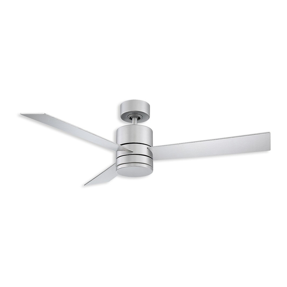
A X IS
F R- W1 8 0 3- 52 L
s
INSTALLATION INSTRUCTIONS
DC
SMART
MOTOR
WET
works with the
modernforms.com
Google Assistant
Table of
Contents
Previous
Page
Next
Page
1
2
3
4
5
Advertisement
Table of Contents
Need help?
Do you have a question about the AXIS and is the answer not in the manual?
Ask a question
Questions and answers
Subscribe to Our Youtube Channel
Related Manuals for Modern Forms AXIS
Fan Modern Forms Osprey Installation Instructions Manual
(36 pages)
Fan Modern Forms OSPREY Installation Instructions Manual
(32 pages)
Fan Modern Forms Aviator Flush Installation Instructions Manual
(30 pages)
Fan Modern Forms Aviator 5 Flush Installation Instructions Manual
(36 pages)
Fan Modern Forms Axis 44 Flush Installation Instructions Manual
(38 pages)
Fan Modern Forms FH-W1803-44L-BZ Installation Instructions Manual
(38 pages)
Fan Modern Forms Aviator Installation Instructions Manual
(34 pages)
Modern Forms Aviator FR-W1811 Manual
(article)
Fan Modern Forms Aviator 5 Installation Instructions Manual
(30 pages)
Fan Modern Forms FH-W1811-5-GH/WG Installation Instructions Manual
(36 pages)
Fan Modern Forms Aviator 70 Installation Instructions Manual
(30 pages)
Fan Modern Forms Axis 52 Flush Installation Instructions Manual
(38 pages)
Fan Modern Forms Aura Installation Instructions Manual
(40 pages)
Modern Forms Aura FR-W2303 Manual
(article)
Fan Modern Forms Axis 52 Installation Instructions Manual
(36 pages)
Modern Forms Axis 44 (FR-W1803-44) Manual
(article)
This manual is also suitable for:
Fr-w1803-52l
Osprey
Fr-w1817-56l
Table of Contents
Print
Rename the bookmark
Delete bookmark?
Delete from my manuals?
Login
Sign In
OR
Sign in with Facebook
Sign in with Google
Upload manual
Upload from disk
Upload from URL


Need help?
Do you have a question about the AXIS and is the answer not in the manual?
Questions and answers