SDC 1511S Installation Instructions Manual
Hide thumbs
Also See for 1511S:
- Nstallation instructions (11 pages) ,
- Installation instructions manual (13 pages) ,
- Installation instructions manual (14 pages)
Table of Contents
Advertisement
Quick Links
801 Avenida Acaso, Camarillo, Ca. 93012 • (805) 494-0622 •
www.sdcsecurity.com • E-mail: service@sdcsecurity.com
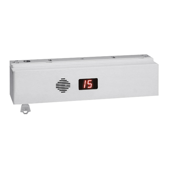
Application
When unauthorized egress is initiated, the Exit Check
An integral digital countdown display and voice commands inform the person intending to exit of the seconds remaining
to unlock. Meanwhile, the person exiting must wait allowing personnel or security respond. The door unlocks after the
15 or 30 second delay period has elapsed, permitting egress. A signal from the fire/life safety system will release the
lock immediately for uninhibited egress in an emergency.
®
Exit Check
applications include:
Restricting the egress of patients for their own safety.
Restricting the egress of commercial center patrons for security application needs.
Controlling pedestrian traffic in transportation facilities, including airport jetways and tarmacs
Standard Features
1650 lbs. Holding Force
15 or 30 Second Exit Delay when activated.
1 or 2 Second Nuisance Delay
75dB Alarm Tone with Digital Display & Selectable Voice
Instruction
Choice of Activation Trigger:
- Door Movement
- Exit Device w/ REX Switch
- Touch Sense Bar w/REX Switch
Auto Power-Up – Occurs when power is restored and/or
the fire panel is restored. (When Allowed by Code)
Manual Power-Up – This is a UBC & California Building
Code Compliant Feature – Only after power restoration
and fire panel reset may the lock be reset manually at the
opening. Lock can be reset with the built-in reset key
switch or, a key switch or keypad adjacent to the door.
Vandal resistant Proximity Sensor Trigger
Auto Sensing 12/24VDC input power
Connection for Tandem Option (Pairs of Doors)
P:\INSTALLATION INST\Delayed Egress\INST-1511ST\INST-1511ST.vsd
INSTALLATION INSTRUCTIONS
®
EXIT CHECK
DELAYED EGRESS EMLOCK
1511S / 1511T
®
delays egress through the door for a period of 15 or 30 seconds.
Rev G7
PUSH UNTIL ALARM
SOUNDS. DOOR CAN BE
OPENED IN 15 SECONDS.
KEEP PUSHING. THIS DOOR
WILL OPEN IN 15 SECONDS.
ALARM WILL SOUND.
Optional Features
D = DPS Door Position Switch
B = BAS Bond Alert Sensor
A = ATS Anti Tamper Switch
E = Energy Saver Option (1200 lb. Holding Force)
Building & Fire Life Safety Code Compliant
IBC International Building Code
IFC International Fire Code
NFPA 101 Life Safety Code
NFPA 1, UFC, Uniform Fire Code
UBC Uniform Building Code
CBC California Building Code
SBC Standard Building Code
BOCA National Building Code compliant
Chicago Building Code compliant
Only the 1511S and the 1511T
have been UL listed as Special
Locking Arrangements to UL
Standard 294, and NFPA 101.
GWXT, GWXT7 - Auxiliary Locks - UL,cUL Listed
FWAX - Special Locking Arrangements - UL Listed
02-19
Page 1
®
California Building
Code Compliant
California State
Fire Marshal Listed
CSFM #3774-0324:103
Advertisement
Table of Contents

Related Manuals for SDC 1511S


Summary of Contents for SDC 1511S
- Page 1 Lock can be reset with the built-in reset key Chicago Building Code compliant switch or, a key switch or keypad adjacent to the door. Only the 1511S and the 1511T Vandal resistant Proximity Sensor Trigger have been UL listed as Special...
- Page 2 Activation / Alarmed Release : Activation of the 1511S Exit Check’s 15 or 30 second unlock cycle is started by releasing the door latch and applying up to 15 lbs. of pressure to the door causing slight door movement. A short nuisance delay period is then initiated, a pre- activation warning tone is sounded and the integral display will start counting down.
-
Page 3: Specifications
TEMPLATE Power Consumption: TEMP-1511 1511S EMLOCK Standard Model (1650 lbs.) - 1511S – 820/500 mA@ 12/24 VDC HOUSING ASSY. & MOUNTING PLATE 1511T – 1500/850 mA @ 12/24 VDC Energy Saver (1200 lbs., “E” Option) – 1511S – 452/274 mA@ 12/24 VDC 1511T –... - Page 4 1/4” DIA GUIDE PIN HOLE 9/16” DEEP PLACE AGAINST DOOR Center punch on mark STEP 3. Drill and tap the two 1511S mounting holes as indicated on the paper template. (NOTE: READ NOTE ON TEMPLATE WITH REGARD TO SELECTING THE PROPER HOLE PAPER TEMPLATE SIZE FOR ARMATURE MOUNTING BOLT.)
- Page 5 ARMATURE MOUNTING INSTRUCTIONS 1–3/8" DOOR STEP 1. Mount armature to door. (See figures 2A, 2B & 2C.) ARMATURE 5/16 – 18 ARMATURE MOUNTING SCREW SEX NUT STEP 2. Install the mounting plate (filler plate and/or angle bracket if needed – see figures 1A, 1B &...
-
Page 6: Display Modes
Typical System Wiring – AC Mains 2 conductors Single Door (Model 1511S) To Smoke Power To Fire Panel Detection System Supply 2 conductors Display Modes 8 or 10 3 or 5 Door armed and locked. conductors conductors Alarm countdown has ended, PUSH UNTIL ALARM SOUNDS. - Page 7 AC Mains 2 conductors Typical System Wiring – To Smoke Power Pair of Doors (Model 1511T) Detection System Supply To Fire Panel 2 conductors 8 or 10 4 conductors (1511T only) conductors Display Modes Door armed and locked. PUSH UNTIL ALARM PUSH UNTIL ALARM SOUNDS.
- Page 8 Wiring to Infant & Patient Protection Systems System Operation 2 conductors AC Mains 1. Close and hold REX input. The 1511S will be To Smoke Power To Fire Panel in the Bypass mode and will be unlocked. Detection System Supply 2 conductors 2.
-
Page 9: Jumper Settings
ALARM (OPTIONAL) SYSTEM Dry, INPUT EXTERNAL (OPTIONAL) (OPTIONAL) TRIGGER SWITCH SMOKE DETECTION SYSTEM INPUT SDC REX PUSH BAR (OPTIONAL) (OPTIONAL) MONITORING OPTIONS MONITOR RELAY OUTPUT TERMINAL BOARD CONNECTIONS CONFIGURATIONS DOOR POSITION SWITCH [DPS] POWER IN - LOCK STATUS RELAY STATE... -
Page 10: Dip Switch Settings
DIP SWITCH SETTINGS RELEASE NUISANCE J u m p e r O F F (Door Prop Alarm Active) I n s t a l l e d REQ TO EXIT J u m p e r (Door Prop Alarm Inactive) R e m o v e d TRIG TYPE SWITCH... - Page 11 Dip Switch Settings By Model Option Code RELEASE NUISANCE J u m p e r O F F (Door Prop Alarm Active) I n s t a l l e d REQ TO EXIT J u m p e r (Door Prop Alarm Inactive) R e m o v e d TRIG TYPE...
- Page 12 1/8" to 1/4” of door movement and start the delay process. STEP 5. Activation of the 1511S can be made by door movement or an external trigger. When using the door movement method, activation is achieved through the way the armature hardware is designed. When someone unlatches the door and applies up to 15 lbs.
- Page 13 Systems Applications Reference Activation by applying pressure to doors with latching hardware: Power Power PUSH UNTIL ALARM SOUNDS. PUSH UNTIL ALARM SOUNDS. DOOR CAN BE DOOR CAN BE OPENED IN 15 OPENED IN 15 SECONDS. SECONDS. TCC / RCC 728L 101-1A 702RU 101-4AM...
Need help?
Do you have a question about the 1511S and is the answer not in the manual?
Questions and answers