Advertisement
SECURITY DOOR CONTROLS ■ WWW.SDCSECURITY.COM
[t] 800.413.8783 ■ 805.494.0622 ■ E-mail: service@sdcsecurity.com ■ 801 Avenida Acaso, Camarillo, CA 93012 ■ PO Box 3670, Camarillo, CA 93011
Application:
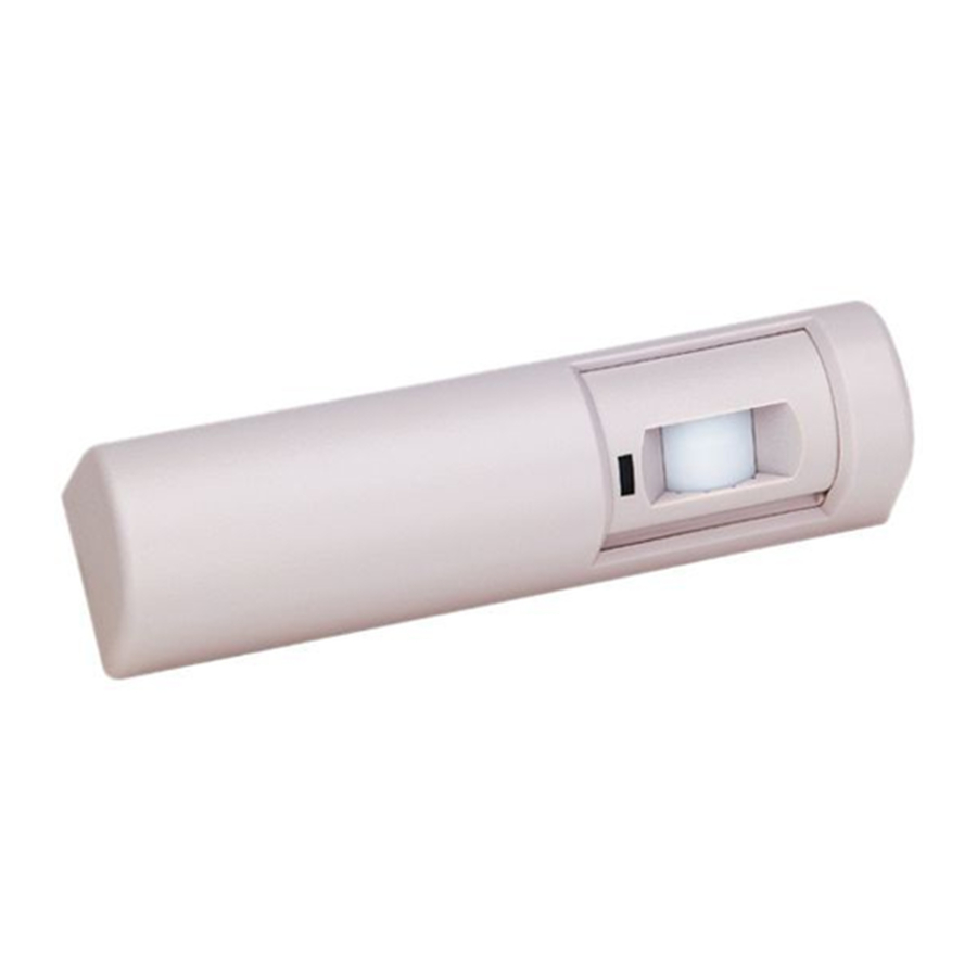
The MD-31DOW combines a passive-infrared detector with relay
output to allow control of door ingress and egress in request-to-exit
(REX) applications. It is UL Listed as an access control device under
the UL 294 standard. It is for indoor use only. MD-31DOW is not
designed for use as the primary means of exit for emergency egress.
MD-31DOW can be ceiling or wall mounted over the door and the
detection pattern can be tailored via vertical aim adjustment and/or
masking of the detection pattern.
The relay outputs consist of two Form "C" contacts that can be
adjusted to latch from 0.5 second to 64 seconds. Resettable or non-
resettable can be selected for the latch time. The relay can also be
programmed to fail safe (doors unlocked) or fail secure (doors
locked) mode in the event of a power loss.
Product specifications:
• Voltage input: 12 VDC or VAC; 24 VDC or 24VAC
• Current draw: 16mA @ 12VDC (see Current Ratings on page 4)
• NO INTERNAL BATTERY. Budget 38mAh per hour standby
• REX detector output: 2 Form C relay contacts rated 2A 30VDC/VAC
maximum for DC resistive loads
• Indicator: Green LED for PIR detection
• Relay latch duration: Adjustable from 0.5 second to 64 seconds
• Timer modes: Selectable for resettable (cumulative) or non-resettable
(counting)
• Power loss operation modes: Selectable for fail safe (doors unlocked)
or fail secure (doors locked)
• Mounting locations: Above controlled door(s), on door frame, wall or
ceiling
• Mounting height: 7' to 15'
• Housing: High impact ABS plastic
• Dimensions: 7"W X 1.75"H X 1.88"D (178W X 44H X 48D mm)
• Operating temperature: -20°F to 120°F (-29°C to 49°C); RH: 0-85%
• RFI immunity: 26MHz to 1000 MHz @ 50 V/m (FCC)
Wiring:
P:\INST INSTRUCTIONS\Accessories\INST-MD-31DOW
Installation INSTRUCTIONS
MD-31DOW
REV A
09-20
All wiring connections should be made and verified before any
power is connected to the detector. All power, including
standby battery if used, should be disconnected.
Connect wires to terminals as follows:
(-) COMMON
+12 OR 24 VDC/VAC
Use EMF (voltage) spike-protected relay
when connecting inductive loads to the detector
to protect against possible harmful EMF spikes.
Use Non EMF (voltage) spike-protected relay
for non-inductive loads. When connecting an
inductive load to this relay that is not spike
Non EMF
EMF
protected, use either a 1KV 1A diode or 100V
(voltage)
(voltage)
4A bridge rectifier (See illustration below).
spike
spike
Otherwise relay life may be shortened.
protected
protected
relay
relay
NON EMFSPIKE-PROTECTED RELAY
Most UL 1034 listed magnetic locks are already EMF spike-protected
and therefore do NOT require a diode or bridge rectifier, and adding
either could cause response delays. Check magnetic lock specifications.
Choose either Fail Safe or Fail Secure operation and wire to
either EMF or Non EMF contacts as follows:
FAIL SAFE
(Switch 2 On)
Power OFF
FAIL SECURE
(Switch 2 OFF)
Power OFF
Page 1
NON EMF SPIKE-PROTECTED RELAY
FAIL SAFE
FAIL SAFE
(Switch 2 On)
(Switch 2 On)
No Motion
Motion Detected
FAIL SECURE
FAIL SECURE
(Switch 2 OFF)
(Switch 2 OFF)
No Motion
Motion Detected
,
Advertisement
Table of Contents

Related Manuals for SDC MD-31DOW


Summary of Contents for SDC MD-31DOW
- Page 1 (REX) applications. It is UL Listed as an access control device under Connect wires to terminals as follows: the UL 294 standard. It is for indoor use only. MD-31DOW is not designed for use as the primary means of exit for emergency egress.
- Page 2 In addition, ensure there is no interference with functioning detector positioning. of any panic devices associated with the system MD-31DOW is To mask the PIR detection pattern, insert masking wedges using connected to. small holes at top and bottom of PIR lens on outside surface of DIP SWITCH 3-LED Enable/LED Disable selection detector.
- Page 3 The body heat (IR energy) of a person moving through a zone triggers the detector. When wall mounted at a height of 7’ with the detector aimed downward by 14°, the MD-31DOW produces approximately the following coverage pattern on the floor as seen from...
- Page 4 Important Note: MD-31DOW is designed for installation by properly trained, experienced and qualified low-voltage technicians. It should be installed in compliance with all applicable local, regional and ACCESS CONTROL national electrical and safety codes.
Need help?
Do you have a question about the MD-31DOW and is the answer not in the manual?
Questions and answers