Table of Contents
Advertisement
Quick Links
Advertisement
Table of Contents

Subscribe to Our Youtube Channel
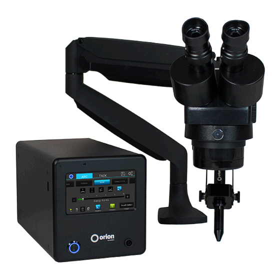
Summary of Contents for Orion c Series
- Page 1 Orion c Series Welding System User Manual...
-
Page 2: Table Of Contents
Make a Tack Weld . . . . . . . . . . . . . . . . . . . . . . . . . . . . p . 1 8 Orion 100c Pulse Arc and Resistance Welder Weld Modes... - Page 3 OrionWelders.com...
-
Page 4: What Is In The Box
Power Supply Setup SET UP THE BACK SIDE OF THE POWER SUPPLY The Orion has an internal switching power supply that can accept both 120 and 240VAC . • Plug the female end of the power cable into the “90-240 VAC” Power port . -
Page 5: Microscope Arm Setup
SET UP THE FRONT SIDE OF THE POWER SUPPLY Look to the front on the Orion to power on the welder and control the touch screen . • Plug the pulse arc welding alligator clip in the port at the bottom right of the welder . - Page 6 Ensure the microscope cable is plugged into the “Shutter” port on the back of the power supply . *Orion RJ45 ports are not compatible with any other RJ45 ports . Connecting them to other devices may damage the welder and/or the other devices .
-
Page 7: Microscope Lcd Filter Shutter
The microscope LCD filter shutter allows an unobstructed working view before welding and completely protects the user’s eyes during the welding process . The Orion’s internal computer verifies the microscope LCD filter shutter has been closed before allowing the weld to take place . In the case that the shutter does not close, the microscope lens is equipped with >UV 16 and >IR 16 for maximum eye protection . -
Page 8: Become Familiar With The Microscope
Become Familiar with the Microscope The Orion Microscope has been designed to provide maximum visual clarity, eye protection and ease of use . One challenge using the microscope is getting used to bringing the work piece to the welding electrode while looking through the microscope . -
Page 9: Electrode Setup
Electrode Setup The Orion welder comes standard with a 0 .5mm electrode collet and (5) 0 .5mm electrodes; and a 1 .0mm electrode collet and (5) 1 .0mm electrodes . The 1 .0mm electrodes are a good all around electrode while the 0 .5mm electrode is more for very small applications (less than 5ws of energy) . -
Page 10: Shielding Gas Setup
Series User Manual • Pinch the electrode between the thumb and index and/or middle finger with the shaft going perpendicular to the fingers . • Power on the Dremel or flex shaft then hold it with the opposite hand . *Place the electrode tip in the diamond disc in such a way that the grit of the disk is moving parallel with the electrode shaft and moving towards the tip . - Page 11 the tank could become rocket-like, expelling the high pressure shielding gas as propellant . • Always turn off the shielding gas at the main valve when finished . This will help your shielding gas supply last longer in case there is a small leak in the tubing . This is also a good safety practice .
-
Page 12: Arc Screen
Series User Manual Chapter 2: The Touch Screen Interface Below is an explanation of all the various buttons and options found on the Orion user interface . Arc Screen 1 . Top Navigation Bar: Allows the user to change screens . -
Page 13: Tack Screen
Tack Screen 1 . Top Navigation Bar: Allows the user to change screens . 1 . Arc Button: Switches the Main Screen to the Arc Screen 2 . Tack Button: Switches the Main Screen to the Tack Screen 3 . Save Load Button: Brings up the Save Load Window 4 . -
Page 14: Save/Load Screen
Series User Manual Save/Load Screen 1 . List of Saved Welds: Current list of welds that are saved on the welder . Currently the max is 30 . 1 . Number of the weld . 2 . Weld Button: Contains a short description of the saved weld . - Page 15 Turkish, Vietnamese, Finish, Russian, Armenian, Hindi, Korean, Chinese, Taiwanese 6 . Exit Button: Exits out of the settings screens and returns to the last screen the user was on . Settings: Gas Screen 1 . Top Navigation Bar: Allows the user to change screens .
- Page 16 Series User Manual 2 . Pre-Weld Delay Slider: Allows the user to adjust the time between trigger and weld . 1 . Current Value: Shows the user what the current value is . 2 . Slider Bar: Allows the user to adjust the value .
- Page 17 WELDER SOFTWARE Orion users are able to receive software and welder setting updates via email . As Orion engineers develop new software with more efficient settings and/or features to help users have the very best welding experience, they will place the update on the Orion website for user to download .
-
Page 18: Chapter 3: Make A Weld
Series User Manual Chapter 3: Make a Weld Gray Waveform • When the welder is paused the waveform screen will appear gray . Remember to push play in order to perform welds . Make An Arc Weld (using the provided weld plate) 1 . - Page 19 Electrode Shaping: Stylus Cone Stylus Cone Sharp Electrode Tip Flat Electrode Tip Electrode placement examples: Add Metal Weld Butt Weld Add Metal Weld T-Joint Weld Add Metal Weld 26 AWG wire/chain/jump ring Earring Post Metal Tip Shape Energy Length Agitation Metal Tip Shape Energy...


Need help?
Do you have a question about the c Series and is the answer not in the manual?
Questions and answers