Table of Contents
Advertisement
Advertisement
Table of Contents

Related Manuals for Orion 250i2 EV CNC


Summary of Contents for Orion 250i2 EV CNC
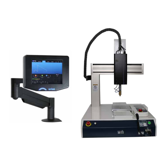
- Page 1 Orion Welder User Manual 250i2 EV CNC...
-
Page 2: Table Of Contents
Table of Contents Chapter 1: Introduction . . . . . . . . . . . . . . . . . . . . . . . . . . . p . -
Page 3: Chapter 1: Introduction
Thank you for choosing Orion Welders and congratulations on your purchase! You are now the proud owner of a Orion 250i2 EV CNC System. This manual was designed to have you welding safely within minutes of unpacking your new welder. Please read and follow all safety precautions before proceeding with the welding process. -
Page 4: Chapter 2: Welder And Cnc Setup
• Connect power cord . Step 2: Determine how to mount the Orion 250i2 welder There are two options . One option is to mount the welder next to the CNC table . This option is best when planning to make hand-held welds in addition to making automated welds . The second option does not involve the use of the microscope or hand held stylus . - Page 5 STEP 3: CONNECT THE WELDER TO THE ARM Insert the welder into the top of the arm . Then use an Allen wrench to secure the welder in place on the arm . *If you purchased the microscope version follow steps 4 - 5 STEP 4: INSERT RUBBER EYEPIECE SHIELDS Place the rubber eyepiece shields over the microscope eyepieces .
- Page 6 OPTION 2: MOUNT THE WELDER TO THE SIDE OF THE CNC TABLE STEP 1: CONNECT THE WELDER TO THE SIDE BRACKET ON THE CNC TABLE Step 3: Connect the power cable and AC power 1 . Plug the power cable into the back of the welder .
- Page 7 2 . Turn the regulator dial COUNTER CLOCKWISE (closed) until it is fully backed out to prevent over-pressurization of the line . 3 . Screw the gas regulator onto the shielding gas tank . 4 . Connect one end of the gas tubing into the gas regulator . It will stop when it is fully connected .
- Page 8 Step 5: Connect the Janome to the welder Use the provided cable that contains a 3 PIN and RJ-45 connector on one end and a 25 PIN parallel connector on the other end to connect the Jonomi to the welder . Plug the 3 DIN connector into the “Trigger”...
- Page 9 Step 7: Connect the EV weld head to the welder using the RJ-11 cable Plug the RJ-11 jack from the cable chain wire harness into the “Acc . Port” on the back of the welder then to the port on the weld head that reads “to welder”...
-
Page 10: Chapter 3: Electrode Setup
Step 10: Power the welder and the EV weld head Power the welder with the button on the bottom of the welder, then turn on the weld head with the switch found on the side . Once both are powered the welder interface should display the EV mode screen . -
Page 11: Chapter 4: User Interface
Chapter 4: User Interface The Orion i2 automatically detects when an EV weld head is connected to the “Acc . Port” and is powered on . If the 250i2 fails to detect the weld head, refer to the FAQ page in this user manual for common solutions . - Page 12 The Triangle waveform is similar to the classic waveform’s ability to make smooth and uniform TRIANGLE - weld results . One key advantage of the triangle waveform is the ability to set the peak and the length independently . Meaning, a weld could have a very high peak and a very short time, or a very low peak with a very long time, or any other combination of these two parameters .
- Page 13 AGITATION During the weld, a high frequency agitation feature can be used to improve weld formation and strength . Additional energy is added to the weld in the form of micro energy bursts . These energy bursts occur at a rate of up to 600 times per second .
- Page 14 PLAY/PAUSE, UNDO, AND RESET OPTIONS Pressing the Play/Pause icon, toggles between Play and pause . If the Play icon is green, the PLAY/PAUSE - welder is capable of making welds anytime a work-piece (connected to the positive alligator clip) makes contact with the electrode .
- Page 15 WELD INDICATORS Power on the Orion 250i2 . Once powered on, there are two indicator dots in the top left corner of the screen . The top dot indicates the Weld Ready signal . The bottom dot indicates the Weld Good signal .
-
Page 16: Chapter 5: Welding With Pendant
1 . Plug in the power cord on the back of the CNC table . 2 . Power on the CNC table using the power switch on the back of the CNC table . 3 . If not already on, turn on the Orion 250i2 and the weld head . - Page 17 Step 3: Initialize the robot by pressing the “F4” button on the pendant . You will notice the text right above the “F4” key indicating “INIT” on the screen . The text above each of the “F” keys will always display their function . Step 4: Make sure the pendant is set in the ‘Teaching Mode .
- Page 18 Step 6: 1 . Press the word “Ignition” to open the advanced settings menu for the ignition settings . 1 . Set the Lift-off Delay between 100-110 uS . 2 . Set the Minimum Time Between Welds to 50ms . 3 .
- Page 19 Step 9: 1 . Press “F2” to select the “JOG” mode . 1 . Next, pressing the XYZ arrow buttons will move the robot in each respective direction . The X buttons will slide the plate forward (-) and backward (+) relative to the front of the CNC table .
- Page 20 Step 13: The screen should now show a “P2” in the top right corner . The robot is still at the “P1” coordinates . To move to the next weld spot, make sure the “JOG” state is selected by pressing “F2 . ” Step 14: To move the robot to the next point: 1 .
- Page 21 Step 18: The next step is to press the “MENU” button to make additional changes . Choose “Individual Program Settings” and press “ENTR . ” Choose “Weld Settings” and press “ENTR” button . (Use the up/down cursor buttons to navigate) . Step 19: These next settings will apply to each weld point coordinate in the program .
- Page 22 Step 22: Nothing that has been done so far has been saved to memory, so press the “SAVE” button at this point . You will see the screen display “Saving Data . ” Wait a moment and it will return to your previous screen . Step 23: At this point we have two weld points saved .
- Page 23 Step 25: PLC inputs and outputs Next we will experiment with the PLC inputs and outputs . 1 . If not already set, pick a weld point and press “GO” to move the robot to one of the already configured weld points . 2 .
- Page 24 “Program 1” is displayed in the top left of the screen . Step 29: In the top left of the Orion 250i2 screen, the PLC weld ready and weld good signals are displayed for your convenience . These two dots will display the same information we just looked at on the I/O Test screen on the pendant .
-
Page 25: Chapter 6: Welding With Computer
Chapter 6: Welding with Computer Step 1: To use the Janome with a PC computer, it must be connected through a local area network (LAN) . First, hook up the Ethernet RJ45 cable from your network or router . The second step requires us to find the IP address of the Janome . - Page 26 Step 5: Once you have the IP address, you will need to disconnect the hand held pendant and connect the Bypass Connector into the TPU connector on the Janome before proceeding with setup . Step 6: 2 . The next few steps will focus on setting up the welding parameters .
- Page 27 Step 8: Setup your fixture to the table . M4 screws can be used to mount directly to plate . Step 9: Install the JR-C-Points (Sunstone) software . Next, open the software . Click on “Robot” in the menu bar, and then drop down and click on “Ethernet Settings .
- Page 28 Step 12: Click on “Robot” in the menu bar again . Drop down and then click on “Receive C&T Data . ” Step 13: A popup windown will appear . Click the “Receive” button to initiate communication between your PC and the Janome . Step 14: Once the PC and Janome finish communicating, another popup window will appear .
- Page 29 Step 16: This is home position . Step 17: Click on “Edit” in the menu bar . Drop down and click on “Add Point . ” Step 18: Under the point that was just created, click the drop down for “Type”...
- Page 30 Step 20: 1 . These cursors are used to move the robot head around . Click on the buttons to move the robot . For this particular robot the “X” controls the plate movement . The “Y” and “Z” controls the head movement .
- Page 31 Step 24: In order to get the x, y, and z coordinates from the JOG window to the point window, you will need to copy them by highlighting the number in the JOG window and right clicking with the mouse and clicking “Copy .
- Page 32 Step 29: Click on “Program” in the menu bar . Drop down and click on “Individual Program Settings . ” Step 30: On the “Individual Data” tab, click on the “Weld Settings” button . Step 31: Click each of the values above and change them to the following: Weld Timeout = 6 seconds .
- Page 33 To move the weld head to one of the programmed weld points, click on the point, and then click the “Go Move” icon . The robot will move to that location, but will not yet send a signal to Orion i2 CNC EV to weld .
- Page 34 • The electrode stuck to the surface . • If this happens you will want to increase the lift off delay in the ignition settings screen on the Orion 250i2 screen . • The electrode was too far from the surface, so you will want to decrease the lift off delay in the ignition settings screen on the Orion 250i2 screen .
-
Page 35: Chapter 7: Operation
Step 37: If you click the “Point Playback” icon the robot will go to the currently selected point and make a weld . In this case you will not need to trigger the weld, because the robot will automatically do this for you . Step 38: You can have the robot automatically run though each point and weld and then return to home by clicking on the “Test Run”... - Page 36 Typical applications will be performed in “Triangle Weld Mode” on the i2 screen . Note: Usually, it is a good idea to set the length to max and start with a low power setting (refer to the Orion 250i2 user interface section for more information on each setting) .
- Page 37 • Press the triangle button in the lower left corner of the i2 screen (the button and waveform graph will change colors and the word “Play” will appear below the triangle) . • Use the Pendant to jog the head to a desired weld location . •...
-
Page 38: Chapter 8: Welding Tips And Tricks
CNC EV Compression Force Table COMPRESSION 1/8” 1/4” 3/8” 1/2” 5/8” 3/4” DISTANCE RESULTING SPRING 1 . 5 4 . 5 7 . 5 FORCE Chapter 8: Welding Tips and Tricks Electrode MAINTENANCE The condition of the electrode tip can greatly affect weld quality . As weld slag and oxidation builds up on the electrode, the weld spots can become erratic in size and shape and the arc generation can be affected . - Page 39 GRINDING • The electrode should be sharpened using the included diamond grinding wheel in a high speed rotary tool . • Hold the electrode at about a 15° angle off horizontal and spin the electrode between the thumb and forefinger as it grinds . •...
- Page 40 . Orion 250i2 EV CNC Settings Experimenting with weld parameters can be very educational and lead to a better understanding of welding applications .
- Page 41 The following parameters can be set on the Orion 250i2 EV CNC: MODE The Orion 250i2 EV CNC can discharge energy following three different “Modes . ” • Triangle mode is used for the majority of the applications . The initial peak voltage is high and tapers off in a straight, angled line .
- Page 42 . Take note of the resulting welds . IGNITION TIMING PRESETS Timing can be important for proper arc formation and weld discharge . The Orion 250i2 EV CNC comes with four timing presets .
- Page 43 • Standard mode is useful when using the Orion 250i2 EV CNC in Arc Mode (no weld head plugged in) and welding small wires that can’t withstand the focus arc present in the other modes . • Standard+ ignition mode should be used for most applications and includes a focusing “pre- arc”...
-
Page 44: Chapter 9: Safety
Chapter 9: Safety Read Before Welding ONLY PERSONNEL TRAINED AND CERTIFIED BY THE MANUFACTURER SHOULD SERVICE THE UNIT. Use only genuine replacement parts from the manufacturer . **Contact Sunstone Engineering before opening the unit for any reason** SAFETY PRECAUTIONS The below safety advice is generalized advice for the welding industry . These safety precautions are not all inclusive . - Page 45 • Do not exceed the equipment’s rated capacity . • Use only correct fuses or circuit breakers . Do not oversize or bypass them . SAFETY PRECAUTIONS FOR ELECTRICAL SHOCK Touching live electrical parts can cause fatal shocks or severe burns . Incorrectly installed or improperly grounded equipment is a hazard .
- Page 46 PERSONAL PROTECTIVE EQUIPMENT RECOMMENDATIONS FOR FLYING SPARKS AND ARC RAYS It is essential for every person in the immediate work area to wear/utilize proper personal protection equipment . There is a possibility that sparks can fly off from the weld joint area;...
- Page 47 for metals, consumables, coatings, cleaners, and degreasers . • Do not weld in locations near degreasing, cleaning, or spraying operations . The heat and rays of the weld can react with vapors to form highly toxic and irritating gases . •...
- Page 48 Superintendent of Documents, P . O . Box 371954, Pittsburgh, PA 5250-7954 (phone: 1-866-512-1800) (there are 10 Regional Offices—phone for Region 5, Chicago, is 312-353-2220, website: www . o sha . g ov) . National Electrical Code, NFPA Standard 70, from National Fire Protection Association, P . O . Box 9101, Quincy, MA 02269-9101 (phone: 617-770-3000, website: www .
- Page 49 •Check Weld Timing on the Orion250i2 EV CNC . If the values are not correct, an arc may not be able to initiate . •Make sure the Orion 250i2 EV CNC is in “Play” mode (button on the lower left corner of the screen) . •Make sure the weld energy levels are set high enough for the material being welded .
- Page 50 •Make sure the RJ11 communication cable is firmly plugged into the “Acc . Port” on the back of the Orion 250i2 EV CNC welder and that the opposite side of the cable is plugged in to the weld head correctly . If the cable is damaged, call Sunstone for replacement (normal RJ11 cables should not be used) .
- Page 51 •Check the Tip Retract Delay in the “Ignition menu . ” Decrease this time a little to increase successful welds . Q. WHAT IS THE THICKEST SHEETING THAT CAN BE WELDED? •Weldable sheet thickness varies depending on the type of material . •Highly conductive materials like copper can generally be welded up to 0 .
- Page 52 ORION WELDERS 1693 American Way Suite #5 Payson, UT 84651 1 . 8 77 . 7 86 . 9 353 (toll free) +1 . 8 01 . 6 58 . 0 015 (international) OrionWelders . c om...
Need help?
Do you have a question about the 250i2 EV CNC and is the answer not in the manual?
Questions and answers