
Related Manuals for SEW-Eurodrive CMP ELVCD


Summary of Contents for SEW-Eurodrive CMP ELVCD
- Page 1 *22759468_1117* Drive Technology \ Drive Automation \ System Integration \ Services Operating Instructions Decentralized Extra-Low Voltage Servo Drive CMP ELVCD Edition 11/2017 22759468/EN...
- Page 2 SEW-EURODRIVE—Driving the world...
-
Page 3: Table Of Contents
Electrical installation...................... 22 Installation notes ...................... 22 Installation planning taking EMC aspects into account.......... 22 Installation instructions.................... 23 Installation topology (example) .................. 24 Notes on the supply ...................... 26 CAN bus........................ 27 Positions of the plug connectors ................... 30 Electrical connections .................... 31 Operating Instructions – CMP ELVCD... - Page 4 Parameter description.................... 59 Operation.......................... 73 Operating notes ...................... 73 ELVCD DriveManager .................... 73 Parameter tree ...................... 76 Manual mode ........................ 78 CMP ELVCD status list .................... 81 Service ............................. 83 Malfunctions........................ 83 Evaluating error messages using MultiMotion .............. 84 Function block error messages.................. 84 Fault list......................... 85 Resetting fault messages.................... 88 Unit replacement...................... 88...
-
Page 5: General Information
SEW‑EURODRIVE. Other applicable documentation Observe the manual "Decentralized extra-low voltage servo drive CMP ELVCD – Functional safety". Always use the latest edition of documentations and software. -
Page 6: Structure Of The Instructions
Here you can see the formal structure of instructions and their meaning: ü Prerequisite which must be fulfilled before starting instructions. 1. Step ð Intermediate result of one or more previous steps. ð Final result of all instructions. Operating Instructions – CMP ELVCD... -
Page 7: Rights To Claim Under Limited Warranty
The brands and product names in this documentation are trademarks or registered trademarks of their respective titleholders. Copyright notice © 2017 SEW‑EURODRIVE. All rights reserved. Unauthorized reproduction, modifica- tion, distribution or any other use of the whole or any part of this documentation is strictly prohibited. Operating Instructions – CMP ELVCD... -
Page 8: Safety Notes
• Qualification in the field of mechanics according to applicable national regulation. • They are familiar with this documentation Operating Instructions – CMP ELVCD... -
Page 9: Designated Use
Observe the following notes when transporting the device: • Ensure that the product is not subject to mechanical impact during transportation. If necessary, use suitable, sufficiently dimensioned handling equipment. Operating Instructions – CMP ELVCD... -
Page 10: Installation/Assembly
Make sure that all required covers are installed correctly after electrical installation. Make sure that preventive measures and protection devices comply with the applic- able regulations (e.g. EN 60204-1 or EN 61800-5-1). 2.8.1 Required preventive measure Make sure that the product is correctly attached to the ground connection. Operating Instructions – CMP ELVCD... -
Page 11: Protective Separation
Risk of burns: The surface temperature of the product can exceed 60 °C during opera- tion. Do not touch the product during operation. Let the product cool down before touching it. Operating Instructions – CMP ELVCD... -
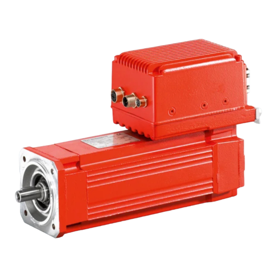
Page 12: Device Structure
Device structure Overview The decentralized extra-low voltage servo drive CMP ELVCD (ELVCD drive) is used in a system that consists of a DC 48 V voltage source and the ELVCD drive. The ELVCD drive is a combination of the following components: •... - Page 13 The ELVCD drive is available with the following ELVCD inverter positions: Standard position 270° (T) (R) 0° 180° (L) 90° (B) 20785610379 Depending on the gear unit design, there may be restrictions regarding the ELVCD in- verter position. Operating Instructions – CMP ELVCD...
-
Page 14: Elvcd Inverter Mounted Close To The Motor
Power plug positions The ELVCD drive with the ELVCD inverter mounted close to the motor can be sup- plied with the following power plug positions: Power plug position 1 Power plug position 3 (default) KKL1 KKL3 20897326859 Operating Instructions – CMP ELVCD... -
Page 15: Elvcd Inverter
The alignment of the plug connectors can be changed if necessary. ELVCD inverter NOTICE If you loosen the 3 screws [6], components may become loose within the ELVCD in- verter. Damage to the ELVCD inverter. • Never loosen the 3 screws [6]. Operating Instructions – CMP ELVCD... -
Page 16: Nameplate
2 0 6 4 9 5 3 3 D E 1 7 . 4 9 0...40 A M B ° C M a d e i n G e r m a n y 20929219211 ID number of ELVCD drive Ambient temperature FS logo Operating Instructions – CMP ELVCD... -
Page 17: Type Designation
ELVCD-EC = drive with mounting close to the motor The ELVCD drive is available as stand-alone motor or gearmotor. Nearly all gear unit designs that can be combined with the CMP50S and CMP50M motors can be realized with the ELVCD drive. Operating Instructions – CMP ELVCD... -
Page 18: Mechanical Installation
The following tables shows the permitted tolerances of the shaft ends and flanges of the ELVCD drive. Shaft end Flanges Diameter tolerance according to EN 50347 Centering shoulder tolerance in ac- cordance with EN 50347 • ISO k6 • ISO j6 • Center hole in accordance with DIN 332, shape DR.. Operating Instructions – CMP ELVCD... -
Page 19: Permitted Mounting Position
• If the corrosion protection coating is damaged, restore the coating. • Check whether the degree of protection specified in the operating instructions and on the nameplate is permitted in the ambient conditions on site. Operating Instructions – CMP ELVCD... - Page 20 Clean the surface of the ELVCD drive and make sure it is free from grease. • Thoroughly cover the breather valves and sealing lip of the oil seals with strips prior to painting. • Remove the strips after painting. Operating Instructions – CMP ELVCD...
-
Page 21: Mounting Close To The Motor
The following figure shows the mounting dimensions for mounting the ELVCD inverter close to the motor: 17823801739 For installation, use 2 M6 screws (preferably hexagon socket head screws or TORX screws) and thread locking compound. Operating Instructions – CMP ELVCD... -
Page 22: Electrical Installation
With respect to the EMC regulation, frequency inverters and ELVCD drives cannot be seen as stand-alone units. Regarding EMC, they can only be evaluated when they are integrated in a drive system. Conformity is declared for a described, CE-typical drive system. These operating instructions contain further information. Operating Instructions – CMP ELVCD... -
Page 23: Installation Instructions
If the contactor is installed in the DC 48 V supply cable, use only a contactor of utilization category DC-3 (EN 60947-4-1). 5.3.3 UL-compliant installation INFORMATION Due to UL requirements, the following chapters are always printed in English inde- pendent of the language of the publication: Operating Instructions – CMP ELVCD... -
Page 24: Installation Topology (Example)
Common reference potential (GND) Diode (optional) External brake chopper and braking resistor (optional) The 24 V electronics supply and the 48 V inverter DC link supply are provided by 1 shared connection cable or by 2 separate supply cables. Operating Instructions – CMP ELVCD... - Page 25 The following figure shows a switching example with digital outputs DO01 and DO02: ® MOVI-PLC DHP11B ELVCD 18077066763 Supply of ELVCD drive Relay Signal lamp The ELVCD drive has 2 parameterizable digital outputs. These can be set using the ELVCD DriveManager. Operating Instructions – CMP ELVCD...
-
Page 26: Notes On The Supply
The ELVCD drive is no longer supplied with 48 V and signals a failure. Further operation is only possible after a reset. Operating Instructions – CMP ELVCD... -
Page 27: Can Bus
No potential shift may occur between the stations of system bus CAN 1. Suitable measures must be taken to ensure that no potential shift occurs between the system bus stations. For example, jumper the CAN_GND reference potential of the stations with a separate cable. Operating Instructions – CMP ELVCD... - Page 28 Length/installation Component type 1 m: Part number 13237748 2 m: Part number 13237756 3 m: Part number 13286315 5 m: Part number 13286331 10 m: Part number 13286358 Fixed length 15 m: Part number 13286366 ELVCD M12, male, A-coded ↔ M12, female, A-coded Operating Instructions – CMP ELVCD...
- Page 29 However, if this is necessary, please con- tact SEW‑EURODRIVE. 5.6.4 Connection cables with right-angle connectors Connection cables with right-angle connectors can be purchased from specialist elec- trical retailers (e.g. PHOENIX CONTACT). Operating Instructions – CMP ELVCD...
-
Page 30: Positions Of The Plug Connectors
Cable bushing of the motor and encoder cables (only for mounting close to the motor) DC 24 V input, DC 48 V input and digital inputs/outputs (→ 2 32) Diagnostic interface (→ 2 41) X40A STO connection (→ 2 38) X401 CAN interface – input (→ 2 39) X402 CAN interface – output (→ 2 40) Operating Instructions – CMP ELVCD... -
Page 31: Electrical Connections
This is why you do not need all listed cables. Cable types The table below shows the depiction and what they mean: Depiction Meaning Set length Variable length Suitable for cable carriers Not suitable for cable carriers Operating Instructions – CMP ELVCD... - Page 32 8 7 6 5 4 3 2 1 Name Function DI01 Digital input DI01, no function/transparent DO02 Digital output DO02, parameterizable (Parameter de- scription) res. Reserved Reference potential for binary signals DI00 Digital input DI00, no function/transparent Operating Instructions – CMP ELVCD...
- Page 33 In order to switch the digital inputs with the DC 24 V electronic supply, pin B4 and pin C1 must be jumpered. In order to switch the digital inputs with the DC 24 V ex- ternal voltage, pin B4 must be jumpered with the reference potential of the external voltage. Operating Instructions – CMP ELVCD...
- Page 34 Permitted connection cross section and current carrying capacity of the terminals Module Contact insert 8‑pin Contact insert 2‑pin Connection cross section 0.14 – 1.5 mm 0.2 – 4 mm Current carrying capacity 10 A 20 A (max. continuous current) Single conductor stripping 6 mm 10 mm length Operating Instructions – CMP ELVCD...
- Page 35 Cable with plug connector M23, 8-pin, female, type: BSTA 078 Connection image Name Function Motor phase U output PE connection Motor phase W output Motor phase V output n.c. Not connected n.c. Not connected Brake + Brake - Operating Instructions – CMP ELVCD...
- Page 36 Signal input, cosine + Signal input, cosine - Signal input, sine + Signal input, sine - n.c. Not connected n.c. Not connected PK/KTY+ Temperature sensor connection PK/KTY+ PK/KTY- Temperature sensor connection PK/KTY- n.c. Not connected n.c. Not connected Operating Instructions – CMP ELVCD...
- Page 37 Signal input, cosine + Signal input, cosine - Signal input, sine + Signal input, sine - RS485 connection - RS485 connection + PK/KTY+ Temperature sensor connection PK/KTY+ PK/KTY- Temperature sensor connection PK/KTY- Reference potential Supply voltage Operating Instructions – CMP ELVCD...
- Page 38 Connection image Name Function +24V DC 24 V output +24V DC 24 V output STO1 DC 24 V input for safe disconnection STO2 DC 24 V input for safe disconnection 0V24 reference potential for safe disconnection Operating Instructions – CMP ELVCD...
- Page 39 CAN interface – input Connection type M12, 5-pin, male, A-coded Connection image Name Function Drain Shield/equipotential bonding CAN bus res. Reserved CAN_GND Reference potential CAN bus CAN_H CAN data line (high) CAN_L CAN data line (low) Operating Instructions – CMP ELVCD...
- Page 40 The following table shows information about this connection: Function CAN interface – output Connection type M12, 5-pin, female, A‑coded Connection image Name Function CAN_SHLD Shield/equipotential bonding res. Reserved Reference potential CAN_H CAN data line (high) CAN_L CAN data line (low) Operating Instructions – CMP ELVCD...
- Page 41 Electrical installation Electrical connections 5.8.10 X5: Diagnostic interface INFORMATION Diagnostic interface X5 may only be used by SEW‑EURODRIVE Service. Never remove the screw plug from diagnostic interface X5. Operating Instructions – CMP ELVCD...
-
Page 42: Startup
• Only use settings that are correct for the function. INFORMATION Observe the safety notes in chapter "Safety notes" > "Startup/Operation". INFORMATION To ensure fault-free operation, do not disconnect or connect signal cables during operation. Operating Instructions – CMP ELVCD... -
Page 43: Requirements
All motor protection equipment is active and set for the rated motor current. • There are no other sources of danger. • The surface of the drive is not covered by heat-sensitive or thermally insulating materials. Operating Instructions – CMP ELVCD... -
Page 44: Additional Information
The description of the application modules can be found in the "Application Configur- ator for CCU" manual. Additional information Further information can be found in the following documents: • Application Configurator • MultiMotion ® • MOVI-PLC libraries Operating Instructions – CMP ELVCD... -
Page 45: Startup With Ccu
ü You know the ID numbers of all ELVCD drives to be started up. The ID numbers can be found on the "motor nameplates" (→ 2 16). ü The "ELVCD-DriveManager" plug-in is installed in MOVITOOLS ® MotionStudio. You can obtain this plug-in from SEW‑EURODRIVE. Operating Instructions – CMP ELVCD... -
Page 46: Startup With Movi-Plc
MotionStudio always has to take place via the "ELVCD DriveManager" plug-in. 1. Select connection type "Ethernet" under "Select connection mode and create net- work". 2. Make sure that you are in Online mode. 3. Right-click on the network icon in the bottom window. Operating Instructions – CMP ELVCD... - Page 47 14. Log in by clicking on menu item [Online] > [Log in]. Confirm the load request by clicking on the [OK] button. 15. Load the PLC project as a boot project by clicking on the [Online] > [Generate boot project] menu item. Operating Instructions – CMP ELVCD...
-
Page 48: Reference Travel
New actual position = current modulo position + offset 12501096203 6.6.2 Zero pulse negative direction Reference travel takes place without motion, by setting the encoder offset to zero pulse in negative direction. New actual position = current modulo position + offset 12501099403 Operating Instructions – CMP ELVCD... - Page 49 Set parameter P303.0 Maximum current as follows: Nominal motor current < Para- meter P303.0 Maximum current < 32 A. 12502413835 6.6.7 Fixed stop negative Reference travel takes place by approaching the stop in negative direction. New actual position = offset Operating Instructions – CMP ELVCD...
-
Page 50: Parameter List
3: On 4: Enabled 5: Rapid stop active 6: Fault 7: STO active 012.0 32780 Fault status Fault number and fault text 013.0 50 Warning status 0: No warning Bit 16 1: Warning active STO status Operating Instructions – CMP ELVCD... - Page 51 Digital output DO02 Inactive/Active Bit 2 (Status of the function that is defined in parameter P621.0) 053.0 32818 Digital output DO03 Inactive/Active Bit 3 (Brake output) Device data 070.0 23 Firmware version (Main e.g.: 3.1 version/subversion) Operating Instructions – CMP ELVCD...
- Page 52 Yes/no Bit 5 nication error 080.4 112 SINCOS track signal fault Yes/no Bit 6 080.5 112 Resolver track signal fault Yes/no Bit 7 or carrier failure 080.6 112 5 V electronics supply Yes/no Bit 8 fault Operating Instructions – CMP ELVCD...
- Page 53 082.8 113 Position data set fault Yes/no Bit 24 082.9 113 Faulty operating mode Yes/no Bit 25 change 083.0 113 Fault in precalculation po- Yes/no Bit 27 sitioning 083.1 113 Stack_Overflow Yes/no Bit 29 Operating Instructions – CMP ELVCD...
- Page 54 Current control 290.0 208 Current controller gain 0.1 – 64 1 Digit = 2 CMP 50S: 2.2 CMP 50M: 2.1 291.0 209 Current controller time constant 0.2 – 100 ms 1 Digit = 0.0001 ms CMP 50S: 1.20 ms CMP 50M: 1.00 ms Operating Instructions – CMP ELVCD...
- Page 55 Limit switch option lock direction 0: Yes (direction of rota- Bit 4 of rotation tion locked) 1: No (direction of rota- tion not locked) 610.1 148 Limit switch type 0: NC contact Bit 2 1: NO contact Digital outputs Operating Instructions – CMP ELVCD...
- Page 56 Bit 4, 5, 6, 7 uration 1 – 2: Reserved 3: PT1000 4: KTY83-1 5: KTY82-1 6: KTY82-2 7: KTY84-1_(SEW) 805.1 37 KTY temperature sensor switch- -40 – 145 – 150 °C 1 Digit = 2 °C off threshold Operating Instructions – CMP ELVCD...
- Page 57 0: No response Bit 25 1: Display warning 2: Rapid stop 3: Immediate stop 836.0 114/ Motor temperature 5 °C below 0: No response Bit 26 maximum limit 1: Display warning 2: Rapid stop 3: Immediate stop Operating Instructions – CMP ELVCD...
- Page 58 1: On Position monitoring 923.0 282 Lag error window (MultiMotion) 0 – 1 –32767 revolutions 1 Digit = 2 rev. 925.0 281 Response delay of lag error 0 – 200 –26214 ms 1 Digit = 0.0001 ms Operating Instructions – CMP ELVCD...
-
Page 59: Parameter Description
DC link voltage The parameter indicates the voltage in %, measured in the DC link of the inverter. Parameter 009.0 Motor temperature The parameter indicates the temperature of the motor in °C. Parameter 009.1 Power section temperature Operating Instructions – CMP ELVCD... - Page 60 STO 1 feedback (PWM power driver off) The parameter indicates that the power driver is switched off. Parameter 024.0 STO 2 feedback (driver supply off) The parameter indicates that the driver supply is switched off. Operating Instructions – CMP ELVCD...
- Page 61 Parameter 051.0 Digital output DO01 The parameter indicates the state of the digital output DO01. The parameter indicates whether the function set in parameter P620.0 is active. Parameter 052.0 Digital output DO02 Operating Instructions – CMP ELVCD...
- Page 62 The parameter indicates the resistance of the motor stator. Parameter 076.0 Torque constant The parameter indicates the torque constant of the motor. Parameter 077.0 Angular encoder type The parameter indicates the encoder type (resolver/sine-cosine encoder). Operating Instructions – CMP ELVCD...
- Page 63 • or the encoder is configured incorrectly. Parameter 080.3 Signal: SINCOS-RS485 communication error The parameter indicates whether • the communication of the sine-cosine encoder is not present • or the encoder is configured incorrectly. Operating Instructions – CMP ELVCD...
- Page 64 The parameter indicates whether • the power supply is not present • or whether the value is set too high. Parameter 081.2 Signal: DC link overvoltage The parameter indicates whether the DC link voltage is > 70 V. Operating Instructions – CMP ELVCD...
- Page 65 The parameter indicates whether both limit switches are active at the same time. Parameter 082.1 Signal: Timeout at rapid stop The parameter indicates whether rapid stop ramp is configured incorrectly. Parameter 082.2 Signal: Reference travel fault Operating Instructions – CMP ELVCD...
- Page 66 The parameter indicates whether the output stage was switched on during operating mode change. Parameter 083.0 Signal: Fault during positioning precalculation Contact SEW‑EURODRIVE Service. Parameter 083.1 Signal: Stack overflow Contact SEW‑EURODRIVE Service. Parameter 083.2 Signal: Checksum error Operating Instructions – CMP ELVCD...
- Page 67 (ramp inactive, default setting, since profile is defined by MOVI-PLC • or whether the speed setpoint of the position controller is changed via the internal ramp times. (Ramp active) Parameter 201.0 Speed controller gain This parameter defines the gain factor of the speed controller. Operating Instructions – CMP ELVCD...
- Page 68 The drive does not exceed this speed value even with a setpoint input that is greater than the maximum speed. Parameter 303.0 Maximum current This parameter specifies the maximum current in case of overload. Parameter 305.0 t-time constant This parameter defines the time constant for the motor protection model. Operating Instructions – CMP ELVCD...
- Page 69 Parameter P620.0 defines the function of digital output DO01. Parameter P621.0 defines the function of digital output DO02. You can set the following functions: 0: No function 1: Output stage active 2: I t signal 3: Warning Operating Instructions – CMP ELVCD...
- Page 70 Brake chopper switch-on threshold This parameter determines the switch-on threshold of the brake chopper. Parameter 823.0 Brake chopper switch-off threshold This parameter determines the switch-off threshold of the brake chopper. Parameters 830.0 – 840.0 Fault responses Operating Instructions – CMP ELVCD...
- Page 71 1) The response is set by parameter indexes "114" – "117". Parameter 886.0 CAN address This parameter indicates the current CAN address of the drive. The address is set in MultiMotion. Parameter 887.0 CAN active The parameter defines whether CAN bus is set to active. Operating Instructions – CMP ELVCD...
- Page 72 Parameter 925.0 Response delay of lag error This parameter defines how long the actual position may be outside the tolerance win- dow before the "lag error" message is displayed. Operating Instructions – CMP ELVCD...
-
Page 73: Operation
ELVCD DriveManager The following figure provides an overview of the "ELVCD DriveManager" plug-in: [14] [13] [12] [11] [10] 9007220173594763 [A] "All ELVCD inverters" area The buttons in this area are used on all listed ELVCD drives. Operating Instructions – CMP ELVCD... - Page 74 [9] [Open parameter tree] button Use this button to switch to the parameter tree display. Access to the parameters is possible during operation of the ELVCD drives, and changes become effective imme- diately. Operating Instructions – CMP ELVCD...
- Page 75 In order to execute diagnostic and control functions, the "Online" status must be signaled. This is shown in the form of a continuous green bar. If the "Offline" status is displayed, check the Ethernet connection and its settings. Operating Instructions – CMP ELVCD...
-
Page 76: Parameter Tree
If the "Offline" status is displayed, check the Ethernet connection and its settings. [4] "SBus communication" status display Green: The drives communicate with the controller via the SBus. Initialization can take several seconds after starting the controller. Gray: No communication via the SBus takes place. Operating Instructions – CMP ELVCD... - Page 77 [10] "Parameter" choice box Choice boxes have a white background. You can change the value of the parameter. [11] "Parameter" display field Display fields have a gray background. You cannot change the value of the para- meter. Operating Instructions – CMP ELVCD...
-
Page 78: Manual Mode
The motor axes have been configured. 7.4.2 Start manual mode To start manual mode, proceed as follows: 1. Switch on the 24 V and the 48 V voltage supply of the ELVCD drive. 2. Connect the PC/laptop to the controller via Ethernet. Operating Instructions – CMP ELVCD... - Page 79 Manual mode is activated using this button. Actuation by the controller is prevented. [2] "Setpoint speed" edit box Enter the setpoint speed in user units in the edit box. [3] "Ramp" edit box Enter the ramp in user units in the edit box. Operating Instructions – CMP ELVCD...
- Page 80 Green: The axis is enabled and supplied with current. If a brake is present, it is re- leased. Gray: The axis is not enabled and not supplied with current. If a brake is present, it is applied. Operating Instructions – CMP ELVCD...
-
Page 81: Cmp Elvcd Status List
QUICKSTOP_ The Quick Stop Function is executed. ACTIVE The motor is connected to the voltage supply. The motor is controlled according to the Quick Stop func- tion. Operating Instructions – CMP ELVCD... - Page 82 Operation CMP ELVCD status list Code Operating status Meaning FAULT A fault occurred. The motor is de-energized. STO_SAFESTOP STO has been activated. The inverter safely switches off the motor torque. Brake is applied. Operating Instructions – CMP ELVCD...
-
Page 83: Service
Have brake and brake control replaced by SEW‑EURODRIVE Service. • Contact SEW-EURODRIVE Service. Motor does not brake. Brake lining is worn. • Have brake and motor replaced by SEW‑EURODRIVE Service. Braking torque is wrong. • Contact SEW-EURODRIVE Service. Operating Instructions – CMP ELVCD... -
Page 84: Evaluating Error Messages Using Multimotion
The reference travel search • Adapt the configuration. speed is not within the SPEED_OUT_OF_BOU range of values. 16461833 E_ELVCD_CLEARSPE • The reference travel retrac- • Adapt the configuration. tion speed is not within the ED_OUT_OF_BOUND range of values. Operating Instructions – CMP ELVCD... -
Page 85: Fault List
16 – 32 V. Conflict between • Firmware does not match • Contact SEW-EURODRIVE hardware. Service. hardware and firmware 21008 Current measure- • Internal fault • Contact SEW-EURODRIVE Service. ment offset error Operating Instructions – CMP ELVCD... - Page 86 STO 1 & 2 (STO puts STO 1 & STO 2 are 1 ≠ STO 2) not activated at the same time. 9088 I²t at 80% • The load threshold of 80% • Remove motor blockage. is reached. Operating Instructions – CMP ELVCD...
- Page 87 Check MOVI-PLC for proper time. functioning. • A CAN communication • Check the CAN cable. 33024 CAN communica- error (SBus) has occurred. tion error • Check the shielding. • Switch the drive off and on again. Operating Instructions – CMP ELVCD...
-
Page 88: Resetting Fault Messages
Unit replacement If the device is defective, send it to SEW-EURODRIVE Service or replace it. All com- ponents must be replaced when doing this: Servomotor, inverter and gear unit (if present). Operating Instructions – CMP ELVCD... -
Page 89: Electronics Service By Sew-Eurodrive
Observe the notes on storage temperature in the "Technical data" chapter. 8.10 Extended storage In case of extended storage, connect the unit to the supply voltage for at least 5 minutes every 2 years. Otherwise, the device's service life may be reduced. Operating Instructions – CMP ELVCD... -
Page 90: Waste Disposal
Observe the applicable national regulations. Dispose of materials separately in ac- cordance with the nature of the materials and the regulations in force, for example: • Electronics scrap (circuit boards) • Plastics • Sheet metal • Copper • Aluminum Operating Instructions – CMP ELVCD... -
Page 91: Inspection And Maintenance
Connection cables Check all connection cables for damage or signs of fatigue at regular intervals. Re- place if necessary. Operating Instructions – CMP ELVCD... -
Page 92: Inspection And Maintenance Intervals
You cannot measure the working air gap directly, since the brake is integrated in the motor. • If the permissible total brake work W that was determined during configuration insp been reached, must have brake replaced. Contact SEW‑EURODRIVE. • The BK brake may only be replaced by SEW‑EURODRIVE. Operating Instructions – CMP ELVCD... - Page 93 If braking work of 1000 kJ (brake BP04) and 350 kJ (brake BK02) is reached, you must have the motor and the brake replaced by SEW‑EURODRIVE Service. More information can be found in the "CMP Synchronous Servomotors" catalog. Operating Instructions – CMP ELVCD...
-
Page 94: Technical Data
1.15 Nm 1.5 Nm PWM frequency 10 kHz Interference immunity accord- Category C3 ing to EN 61800-3 Interference emission accord- Category C3 ing to EN 61800-3 Ambient temperature of stand- ϑ -20 °C – +50 °C ard version according to EN 60721-3-3 without derating Operating Instructions – CMP ELVCD... -
Page 95: Mass Moments Of Inertia
CMP50S ELVCD CMP50M ELVCD −4 −4 Without brake 0.42 × 10 kgm 0.67 × 10 kgm −4 −4 With BK02 brake 0.53 × 10 kgm 0.78 × 10 kgm −4 −4 With BP04 brake 0.48 × 10 kgm 0.73 × 10 kgm Operating Instructions – CMP ELVCD... -
Page 96: Masses
When doing this, take a safety addition of at least 15% of the direct current supply into consideration during configuration. CMP50S ELVCD and ELVCD‑DC − − 1 9949 10 1 7266 1 994 10 × × × × × × Operating Instructions – CMP ELVCD... - Page 97 − − 2 35686 10 7 23949 10 2 36917 10 × × × × × × × 10.5.2 Torque-current characteristic curve for CMP50S ELVCD and CMP50S ELVCD-EC M = f(I I / A 9007213050150795 Operating Instructions – CMP ELVCD...
- Page 98 Torque-current characteristic curve for CMP50M ELVCD and CMP50M ELVCD-EC M = f(I I / A 18014411017118475 10.5.4 Dynamic characteristic curve, CMP50S ELVCD and CMP50S ELVCD-EC 1000 1500 2000 2500 3000 3500 n / min 9007213050267787 Operating Instructions – CMP ELVCD...
- Page 99 The following diagrams show the possible thermal capacity utilization of the drives in operation with regenerative sequences. If an external brake chopper and braking res- istor are used, the chopper power loss can be reduced to 0 W (→ 2 26). Operating Instructions – CMP ELVCD...
- Page 100 Technical data Characteristic curves Thermal capacity utilization of CMP50S ELVCD P / W 17437928203 Average chopper power loss Thermal capacity utilization of CMP50M ELVCD P / W 17437930891 Average chopper power loss Operating Instructions – CMP ELVCD...
- Page 101 Thermal capacity utilization of CMP50S ELVCD-EC (mounting close to the motor) P / W 17493675275 Average chopper power loss Thermal capacity utilization of CMP50M ELVCD-EC (mounting close to the motor) P / W 9007216748413579 Average chopper power loss Operating Instructions – CMP ELVCD...
-
Page 102: Brake
Minimum static braking torque (holding torque) at 100 °C 2.4 Nm 4, 100 °C Minimal averaged dynamic braking torque in case of emergency off at 1.9 Nm 1m, 100 °C 100 °C Maximum dynamic braking torque in case of emergency off 5.3 Nm 1max Permitted braking work per braking operation 0.175 kJ Operating Instructions – CMP ELVCD... -
Page 103: Can Connection Cables
TC – tinned copper 10.7.3 Mechanical properties (in total) Mechanical properties (in total) Operating temperature -30 °C to +80 °C Nominal UL operating temperature 80 °C Weight of raw cable 36 lbs/1000 ft. Max. recommended tensile stress 72.3 lbs. Operating Instructions – CMP ELVCD... - Page 104 Nominal value of the direct current resistance of the outer shield Nominal DC resistance at 20 °C (ohm/1000 ft) Nominal attenuation 0.6 (at 1 MHz) Attenuation (dB/100ft) Max. operating voltage – UL 300 V RMS Voltage 20 V RMS (UL AWM Style 2919) Operating Instructions – CMP ELVCD...
- Page 105 Technical data CAN connection cables Electrical properties (in total) Max. recommended amperage 2.1 A per conductor at 25 °C Amperage Operating Instructions – CMP ELVCD...
-
Page 106: Dimension Drawings
Dimension drawing of CMP50S ELVCD 08 472 00 14 CMP50S ELVCD /RH1M /KKL 3 150.5 87.5 ø5.5 173.5 /AK0H /KKL 3 DIN 332 DR M4 49.5 150.5 /RH1M /KKL 1 /AK0H /KKL 1 150.5 21.5 150.5 9007212942147851 Operating Instructions – CMP ELVCD... - Page 107 Dimension drawing of CMP50S BK/BP ELVCD 08 470 00 14 CMP50S BK/BP ELVCD /RH1M /KKL 3 87.5 ø5.5 /AK0H /KKL 3 DIN 332 DIN 332 DR M4 DR M4 49.5 /RH1M /KKL 1 /AK0H /KKL 1 21.5 9007212942154251 Operating Instructions – CMP ELVCD...
- Page 108 Dimension drawing of CMP50M ELVCD 08 473 00 14 CMP50M ELVCD /RH1M /KKL 3 189.5 87.5 ø5.5 212.5 /AK0H /KKL 3 DIN 332 DR M4 49.5 189.5 /RH1M /KKL 1 /AK0H /KKL 1 189.5 21.5 189.5 18014411017120651 Operating Instructions – CMP ELVCD...
- Page 109 Dimension drawing of CMP50M BK/BP ELVCD 08 471 00 14 CMP50M BK/BP ELVCD /RH1M /KKL 3 87.5 ø5.5 ø5.5 /AK0K /KKL 3 DIN 332 DR M4 49.5 /RH1M /KKL 1 /AK0H /KKL 1 21.5 18014411017122827 Operating Instructions – CMP ELVCD...
- Page 110 Technical data Dimension drawings 10.8.5 Dimension drawing of CMP50S ELVCD-EC 08 811 00 16 CMP50S ELVCD EC /SB1 /RH1M ø26.5 40.5 17.5 ø5.5 150.5 173.5 /AK0H /AK1H /EK1H 150.5 DIN 332 DR M4 17926327819 Operating Instructions – CMP ELVCD...
- Page 111 Technical data Dimension drawings 10.8.6 Dimension drawing of CMP50S BK/BP ELVCD-EC 08 812 00 16 CMP50S BK/BP ELVCD EC /SB1 /RH1M ø26.5 40.5 17.5 ø5.5 /AK0H /AK1H /EK1H DIN 332 DR M4 17931296907 Operating Instructions – CMP ELVCD...
- Page 112 Technical data Dimension drawings 10.8.7 Dimension drawing of CMP50M ELVCD-EC 08 813 00 16 CMP50M ELVCD EC /SB1 /RH1M ø26.5 40.5 17.5 ø5.5 189.5 212.5 /AK0H /AK1H /EK1H 189.5 DIN 332 DR M4 17931299595 Operating Instructions – CMP ELVCD...
- Page 113 Technical data Dimension drawings 10.8.8 Dimension drawing of CMP50M BK/BP ELVCD-EC 08 814 00 16 CMP50M BK/BP ELVCD EC /SB1 /RH1M ø26.5 40.5 17.5 ø5.5 /AK0H /AK1H /EK1H DIN 332 DR M4 17931302283 Operating Instructions – CMP ELVCD...
-
Page 114: Declaration Of Conformity
For the assessment, the product was installed in a typical plant configuration. Bruchsal 19.07.2017 Place Date Johann Soder Managing Director Technology a) b) a) Authorized representative for issuing this declaration on behalf of the manufacturer b) Authorized representative for compiling the technical documents Operating Instructions – CMP ELVCD... -
Page 115: Address List
Tel. +55 47 3027-6886 Rua Dona Francisca, 12.346 – Pirabeiraba Fax +55 47 3027-6888 89239-270 – Joinville / SC filial.sc@sew.com.br Bulgaria Sales Sofia BEVER-DRIVE GmbH Tel. +359 2 9151160 Bogdanovetz Str.1 Fax +359 2 9151166 1606 Sofia bever@bever.bg Operating Instructions – CMP ELVCD... - Page 116 Xi'An High-Technology Industrial Development xian@sew-eurodrive.cn Zone Xi'An 710065 Sales Hong Kong SEW-EURODRIVE LTD. Tel. +852 36902200 Service Unit No. 801-806, 8th Floor Fax +852 36902211 Hong Leong Industrial Complex contact@sew-eurodrive.hk No. 4, Wang Kwong Road Kowloon, Hong Kong Operating Instructions – CMP ELVCD...
- Page 117 67670 Mommenheim Cedex Assembly Bordeaux SEW-USOCOME Tel. +33 5 57 26 39 00 Sales Parc d'activités de Magellan Fax +33 5 57 26 39 09 Service 62 avenue de Magellan – B. P. 182 33607 Pessac Cedex Operating Instructions – CMP ELVCD...
- Page 118 Tel. +49 6831 48946 10 Gottlieb-Daimler-Straße 4 Fax +49 6831 48946 13 66773 Schwalbach Saar – Hülzweiler dc-saarland@sew-eurodrive.de SEW-EURODRIVE GmbH & Co KG Tel. +49 7348 9885-0 Dieselstraße 18 Fax +49 7348 9885-90 89160 Dornstadt dc-ulm@sew-eurodrive.de Operating Instructions – CMP ELVCD...
- Page 119 Jakarta 14350 Jakarta PT. Agrindo Putra Lestari Tel. +62 21 2921-8899 JL.Pantai Indah Selatan, Komplek Sentra In- Fax +62 21 2921-8988 dustri Terpadu, Pantai indah Kapuk Tahap III, aplindo@indosat.net.id Blok E No. 27 http://www.aplindo.com Jakarta 14470 Operating Instructions – CMP ELVCD...
- Page 120 Tel. +254 791 398840 Transnational Plaza, 5th Floor http://www.sew-eurodrive.co.tz Mama Ngina Street info@sew.co.tz P.O. Box 8998-00100 Nairobi Latvia Sales Riga SIA Alas-Kuul Tel. +371 6 7139253 Katlakalna 11C Fax +371 6 7139386 1073 Riga http://www.alas-kuul.lv info@alas-kuul.com Operating Instructions – CMP ELVCD...
- Page 121 Fax +264 64 462 734 Strauss Industrial Park anton@dbminingnam.com Unit1 Swakopmund Netherlands Assembly Rotterdam SEW-EURODRIVE B.V. Tel. +31 10 4463-700 Sales Industrieweg 175 Fax +31 10 4155-552 Service 3044 AS Rotterdam Service: 0800-SEWHELP Postbus 10085 http://www.sew-eurodrive.nl 3004 AB Rotterdam info@sew-eurodrive.nl Operating Instructions – CMP ELVCD...
- Page 122 Brazilia nr. 36 Fax +40 21 230-7170 011783 Bucuresti sialco@sialco.ro Russia Assembly St. Petersburg ЗАО «СЕВ-ЕВРОДРАЙФ» Tel. +7 812 3332522 / +7 812 5357142 Sales а. я. 36 Fax +7 812 3332523 Service 195220 Санкт-Петербург http://www.sew-eurodrive.ru sew@sew-eurodrive.ru Operating Instructions – CMP ELVCD...
- Page 123 Fax +27 13 752-8008 Vintonia robermeyer@sew.co.za P.O.Box 1942 Nelspruit 1200 South Korea Assembly Ansan SEW-EURODRIVE KOREA CO., LTD. Tel. +82 31 492-8051 Sales 7, Dangjaengi-ro, Fax +82 31 492-8056 Service Danwon-gu, http://www.sew-eurodrive.kr Ansan-si, Gyeonggi-do, Zip 425-839 master.korea@sew-eurodrive.com Operating Instructions – CMP ELVCD...
- Page 124 Turkey Assembly Kocaeli-Gebze SEW-EURODRİVE Hareket Tel. +90 262 9991000 04 Sales Sistemleri San. Ve TIC. Ltd. Sti Fax +90 262 9991009 Service Gebze Organize Sanayi Böl. 400 Sok No. 401 http://www.sew-eurodrive.com.tr 41480 Gebze Kocaeli sew@sew-eurodrive.com.tr Operating Instructions – CMP ELVCD...
- Page 125 Tel. +84 4 39386666 Quảng Trị - North Vietnam / All sectors except Fax +84 4 3938 6888 Construction Materials nam_ph@micogroup.com.vn 8th Floor, Ocean Park Building, 01 Dao Duy http://www.micogroup.com.vn Anh St, Ha Noi, Viet Nam Operating Instructions – CMP ELVCD...
-
Page 126: Index
Dynamic characteristic curve BW.... 100, 101 Checksum error, P083.2 ........ 66 Clearance during installation ....... 20 Configuring digital output DO01, P620.0 ..... 69 Electrical connection ........... 10 Configuring digital output DO02, P621.0 ..... 69 Electrical installation .......... 22 Operating Instructions – CMP ELVCD... - Page 127 Input STO 1, P025.0.......... 61 Malfunctions on the ELVCD drive ....... 83 Input STO 2, P026.0.......... 61 Maximum current, P303.0 ........ 68 Inspection Maximum speed, P302.0........ 68 Inspection intervals......... 92 Mechanical installation ........ 18 Permitted mounting position...... 19 Operating Instructions – CMP ELVCD...
- Page 128 Protective separation........... 11 Preparation.......... 45, 46 Requirements for startup........ 43 With CCU ............ 45 Rapid stop delay SINCOS, P136.0 ..... 67 Stator inductance, P075.0 ........ 62 Reference travel fault, P082.2 ...... 65 Stator resistance, P075.1 ........ 62 Operating Instructions – CMP ELVCD...
- Page 129 Travel program, invalid jump destination, P082.5 66 Assignment............. 40 Travel program: unknown fault, P082.4 .... 66 Connection cables, available...... 28 Type designation .......... 17 X40A.............. 38 UL compliant installation ........ 23 Zero position after reference travel, P907.0 .. 72 Operating Instructions – CMP ELVCD...
- Page 132 SEW-EURODRIVE—Driving the world SEW-EURODRIVE GmbH & Co KG Ernst-Blickle-Str. 42 76646 BRUCHSAL GERMANY Tel. +49 7251 75-0 Fax +49 7251 75-1970 sew@sew-eurodrive.com www.sew-eurodrive.com...
Need help?
Do you have a question about the CMP ELVCD and is the answer not in the manual?
Questions and answers