Table of Contents
Advertisement
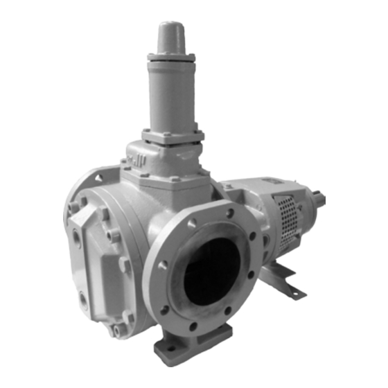
TopGear GP
I N T E R N A L G E A R P U M P S
A . 0 5 0 0 . 4 5 1 – I M - TG G P / 0 7 . 0 2 E N ( 0 3 / 2 0 1 6 )
O R I G I N A L I N S T R U CT I O N S
R E A D A N D U N D E R S TA N D T H I S M A N UA L P R I O R TO O P E R AT I N G O R S E R V I C I N G T H I S P R O D U CT.
I N S T R U CT I O N M A N UA L
Advertisement
Table of Contents

Related Manuals for SPX FLOW TopGear GP Series


Summary of Contents for SPX FLOW TopGear GP Series
- Page 1 I N S T R U CT I O N M A N UA L TopGear GP I N T E R N A L G E A R P U M P S O R I G I N A L I N S T R U CT I O N S A .
- Page 2 EC-Declaration of conformity Machinery Directive 2006/42/EC, Annex IIA Manufacturer SPX Flow Technology Belgium NV Evenbroekveld 2-6 BE-9420 Erpe-Mere Belgium Herewith we declare that TopGear GP-range Gear Pumps Types: TG GP2-25 TG GP3-32 TG GP6-40 TG GP15-50 TG GP23-65 TG GP58-80...
-
Page 3: Table Of Contents
Contents Introduction ________________________________________________7 1.1 General ____________________________________________________7 1.2 Reception, handling and storage _______________________________7 1.2.1 Reception _________________________________________________ 7 1.2.2 Handling __________________________________________________ 7 1.2.3 Storage ___________________________________________________ 7 1.3 Safety _____________________________________________________8 1.3.1 General ___________________________________________________ 8 1.3.2 Pump units ________________________________________________ 9 1.3.2.1 Pump unit handling ______________________________________9 1.3.2.2 Installation _____________________________________________9 1.3.2.3... - Page 4 3.17 Shaft sealing _____________________________________________ 24 3.17.1 Packed gland (no lantern ring) _______________________________24 3.17.2 Packing ring materials ______________________________________24 3.18 Safety relief valve __________________________________________ 25 3.18.1 Pressure _________________________________________________26 3.18.2 Heating __________________________________________________26 3.18.3 Safety relief valve – Relative adjustment _______________________26 3.18.4 Sectional drawings and part lists _____________________________28 3.18.4.1 Single safety relief valve ________________________________ 28 3.18.4.2...
- Page 5 3.21 Trouble shooting ___________________________________________ 43 3.21.1 Instructions for re-using and disposal _________________________45 3.21.1.1 Re-use ______________________________________________ 45 3.21.1.2 Disposal _____________________________________________ 45 3.22 Maintenance instructions ___________________________________ 46 3.22.1 General __________________________________________________46 3.22.2 Preparation _______________________________________________46 3.22.2.1 Surroundings (on site) __________________________________ 46 3.22.2.2 Tools ________________________________________________ 46 3.22.2.3 Shut-down ___________________________________________ 46 3.22.2.4...
- Page 6 4.7 Electrical heating __________________________________________ 57 4.7.1 General __________________________________________________57 4.7.2 Electrical heating on the pump cover (in the idler pin) ____________57 4.7.2.1 Disassembly __________________________________________ 57 4.7.2.2 Assembly ____________________________________________ 57 4.7.3 Electrical heating around shaft seal (in the intermediate casing) ___58 4.7.3.1 Disassembly __________________________________________ 58 4.7.3.2 Assembly ____________________________________________ 58...
-
Page 7: Introduction
The first digits of the serial number indicate the year of production. SPX Flow Technology Belgium NV Evenbroekveld 2-6, BE-9420 Erpe-Mere www.johnson-pump.com / www.spxflow.com 1.2.2 Handling Check the mass (weight) of the pump unit. All parts weighing more than 20 kg must be lifted using lifting slings and suitable lifting devices, e.g. -
Page 8: Safety
Safety 1.3.1 General Important! The pump must not be used for other purposes than recommended and quoted for without consulting your local supplier. A pump must always be installed and used in accordance with existing national and local sanitary and safety regulations and laws. When ATEX pump/pump unit is supplied, the separate ATEX manual must be considered •... -
Page 9: Pump Units
1.3.2 Pump units 1.3.2.1 Pump unit handling Use an overhead crane, forklift or other suitable lifting device. Secure lifting slings around the If there are lifting rings on both Warning front part of the pump and the the pump and the motor the slings Never lift the pump unit with back part of the motor. -
Page 10: Before Commissioning The Pump Unit
When changing the operating conditions of the pump please contact your supplier to ensure a safe and reliable working pump. This also applies to modifications on a larger scale, such as a change of motor or pump on an existing pump unit. SPX Flow Technology Belgium NV Evenbroekveld 2-6 BE-9420 Erpe-Mere www.johnson-pump.com / www.spxflow.com... -
Page 11: Technical Conventions
Technical conventions Quantity Symbol Unit Dynamic viscosity µ mPa.s = cP (Centipoise) ρ = density dm³ µ ν = Kinematic viscosity ρ mm² ν = kinematic viscosity = cSt (Centistokes) Note! In this manual only dynamic viscosity is used. [bar] ∆p Pressure Differential pressure = [bar]... -
Page 12: Pump Description
2.0 Pump description TopGear/GP pumps are rotary positive displacement pumps with internal gear. They are made of cast iron. TG GP pumps: heating/cooling jackets (steam), several sleeve bearings, gear and shaft materials and mounted relief valve and electrical heating. Type designation The pump properties are encoded in the following type indication, which is to be found on the name plate. - Page 13 Examples: TG GP 58-80 G 2 S S SG 2 B G2 TC 10 11 TG GP 15-50 FD G 3 O S UG 6 U G6 AW 10 11 7. Jacket options for pump cover Pump cover without jackets Pump cover with jacket and thread connection Electrical heating idler pin –...
- Page 14 Examples: TG GP 58-80 G 2 S S SG 2 B G2 TC 10 11 TG GP 15-50 FD G 3 O S UG 6 U G6 AW 10 11 11. Bush on shaft materials Bush in hardened steel Bush in carbon Bush in ceramic Bush in hard metal Bush in bronze...
-
Page 15: General Technical Information
3.0 General technical information Pump standard parts Top cover Intermediate casing Pump shaft Bearing bracket Idler pin Rotor Pump cover Idler gear Pump casing Operating principle As the rotor and idler gear unmesh, an underpressure is created and the liquid enters the new created cavities. Liquid is transported in sealed pockets to the discharge side. -
Page 16: Self-Priming Operation
3.2.1 Self-priming operation TopGear pumps are self-priming when sufficient liquid is present in the pump to fill up the clearances and the dead spaces between the teeth. (For self-priming operation see also section 3.19.6.2 Piping). 3.2.2 Safety relief valve – Working principle The positive displacement principle requires the installation of a safety relief valve protecting the pump against overpressure. -
Page 17: Main Characteristics
Main characteristics The pump size is designated by the displacement volume of 100 revolutions expressed in litres (or dm ) but rounded followed by the nominal port diameter expressed in millimetres. ∆p Vs-100 n.max n.mot Q.th Q.th p.test TG GP pump size (mm) (mm) (mm) -
Page 18: Pressure
Pressure Differential pressure or working pressure (p) is the pressure on which the pump normally operates. TopGear GP-line has the maximum differential pressure at 16 bar. The hydrostatic test pressure is 1.5 times the differential pressure i.e.: TopGear GP-line has the hydrostatic test pressure at 24 bar. Following figure gives a graphical presentation of the several kind of pressures. -
Page 19: The Sound Level Of The Pump Unit
Sound power level (L The sound power L is the power emitted by the pump as sound waves and is used to compare sound levels of machines. It is the sound pressure Lp that acts on a surrounding surface at distance of 1 meter. -
Page 20: Material Options
Material options Maximum temperature Overall temperature of TopGear GP pumps is 300°C but: 1. Maximum temperature of size GP2-25, GP3-32 and GP6-40 is limited to 200°C due to ball bearing type 2RS. Minimum temperature is -20°C. 2. Temperature limits must be considered depending on the used materials for bearing bushes and shaft sealing. -
Page 21: Maximum Temperature Of Internals
3.11.2 Maximum temperature of internals For some material combinations the general temperature performances must be limited. The maximum allowable working temperature of internals depends on the combination of used materials and their thermal expansions and the interference fit to hold the bearing bush fixed. •... -
Page 22: Maximum Torque Of Pump Shaft And Rotor Material Combination
3.11.4 Maximum torque of pump shaft and rotor material combination The maximum allowable torque is a constant independent from speed and may not be exceeded to avoid damaging the pump i.e. pump shaft, rotor/shaft fitting and rotor teeth. Mn (nominal torque) in Nm Md (starting torque in Nm N Rotor N Rotor... -
Page 23: Play Between Gear Teeth
The indicated numbers in the tables below are average values in microns (µm). Radial clearance on rotor, idler outside diameter – Axial clearance on pump cover C0 (µm) C1 (µm) C2 (µm) C3 (µm) Pump size axial clearance normal = 2.2 x C1 = 3 x C1 pumpcover set minimum Code rotor... -
Page 24: Shaft Sealing
3.17 Shaft sealing 3.17.1 Packed gland (no lantern ring) 2-25 15-50 86-100 TG GP pump size 6-40 58-80 185-125 360-150 3-32 23-65 120-100 Shaft diameter Section width Number of rings Dimensions in mm 3.17.2 Packing ring materials Most universal solution. Woven shaft packing consisting of PTFE yarns with incorporated graphite and sliding matters (yarns GORE-GFO). -
Page 25: Safety Relief Valve
3.18 Safety relief valve Example V 35 - G 10 H 1. Safety relief valve = V 2. Type indicating = inlet diameter (in mm) Safety relief valve size for TG GP2-25, TG GP3-32, TG GP6-40 Safety relief valve size for TG GP15-50, TG GP23-65 Safety relief valve size for TG GP58-80... -
Page 26: Pressure
3.18.1 Pressure Safety relief valves are divided into 4 working pressure classes i.e. 4, 6, 10 and 16 indicating the maximum working pressure for that valve. Each class has a standard set pressure at 1 bar above the indicated maximum working pressure. The set pressure can be set lower on request never higher. Working pressure class Standard set pressure (bar) Working pressure range (bar) - Page 27 Spring ratio – Safety relief valve Spring dimensions TG GP pump size ∆H [mm] in order Pressure class bar/mm to adjust by 1 bar 25.5 0.26 3.85 2-25 25.5 0.43 2.33 3-32 25.5 1.72 0.58 6-40 25.5 1.72 0.58 37.0 0.21 4.76 37.0...
-
Page 28: Sectional Drawings And Part Lists
3.18.4 Sectional drawings and part lists 3.18.4.1 Single safety relief valve 7400 7240 7030 7330 7040 7180 7100 7100 7110 7300 7310 7320 7050 7170 7010 7150 Single safety relief valve – horizontal 7360 7400 7310 7050 7180 Pos. Description V18 V27 V35 V50 V60 Preventive Overhaul 7010 Valve 7320... -
Page 29: Heated Spring Casing
3.18.4.2 Heated spring casing 7041 Pos. Description V18 V27 V35 V50 V60 Preventive Overhaul Heated spring 7041 casing 3.18.4.3 Double safety relief valve 8020 8050 8020 8050 8010 8010 8040 8060 8040 8070 8030 8070 8060 8030 Double safety relief valve – horizontal Double safety relief valve –... -
Page 30: Installation
3.19 Installation 3.19.1 General This manual gives basic instructions which are to be observed during installation of the pump. It is therefore important that this manual is read by the responsible personnel prior to assembly and afterward to be kept available at the installation site. The instructions contain useful and important information allowing the pump/pump unit to be properly installed. -
Page 31: Indoor Installation
3.19.2.4 Indoor installation Locate the pump so that the motor can be vented properly. Prepare the motor for operation according to instructions provided by the motor manufacturer. When flammable or explosive products are pumped, a proper earthing should be provided. The components of the unit should be connected with earthing bridges to reduce the danger arising from static electricity. -
Page 32: Radial Load On Shaft End
3.19.3.2 Radial load on shaft end The shaft end of the pump shaft may be loaded in radial sense with the maximum radial force (Fr). See table. TG GP pump size Fr (N) - max 2-25/3-32 6-40 15-50/23-65 1000 58-80/86-100/120-100 2000 185-125 3000... -
Page 33: Shaft Rotation For Pump With Safety Relief Valve
3.19.5 Shaft rotation for pump with safety relief valve The shaft rotation determines which port of the pump is suction and which is discharge. The relation between the shaft rotation and the suction/discharge side is indicated by the rotation arrow plate attached at the valve casing of the safety relief valve. TG 2-25 TG 23-65 TG 58-80... -
Page 34: Suction And Discharge Pipes
3.19.6 Suction and discharge pipes 3.19.6.1 Forces and moments Note! Excessive forces and moments on the nozzle flanges derived from piping can cause mechanical damage to pump or pump unit. Pipes should therefore be connected in line, limiting the forces on the pump connections. Support the pipes and make sure they remain stress-free during operation of the pump. -
Page 35: Isolating Valves
Self-priming operation At the start sufficient liquid must be available in the pump filling up the internal clearance volume and the dead spaces, allowing the pump to build up a pressure difference. Therefore, for pumping low viscosity fluids, a foot valve with the same or larger diameter than the suction pipe must be installed or the pump can be installed without foot-valve but in U-line. -
Page 36: Heating Jackets
3.19.7.2 Heating jackets 1. S-type jackets The S-jackets are designed for use with saturated steam (max 10 bar ⇒ 180°C) or with non- dangerous media (max 10 bar - max 200°C). They are provided with threaded connections Bl (see chapter 6.0 for the dimensions). The connection can be done by threaded pipes or pipe connections with sealing in the thread (conical thread applying ISO 7/1) or sealed outside the thread by means of flat gaskets (cylindrical thread applying ISO 228/1). -
Page 37: Guidelines For Assembly
3.19.8 Guidelines for assembly When a bare shaft pump is delivered, the assembly with drive is the responsibility of the user. The user also must provide all necessary devices and equipment allowing a safe installation and commissioning of the pump. 3.19.8.1 Transport of pump unit •... -
Page 38: Combustion Engines
Electrical equipment, terminals and components of control systems may still carry live current when at rest. Contact with these may be fatal, resulting in serious injury or cause irreparable material damage. Line Motor U (volt) 230/400 V 400 V U 1 V 1 W 1 U 1 V 1 W 1 delta star... -
Page 39: Guarding Of Moving Parts
Repeat this check at operating temperature and spend time achieving minimum alignment deviation. Fit the protecting guard. See the figure below and the corresponding table for the maximum allowed tolerances for aligning the coupling halves. Alignment tolerances - Va External diameter of coupling [mm] [mm] [mm]... -
Page 40: Instructions For Start-Up
3.20 Instructions for start-up 3.20.1 General The pump can be put into service when all arrangements described in chapter 3.19 Installation have been made. • Prior to commissioning, responsible operators have to be fully informed on proper operation of the pump/pump unit and the safety instructions. This instruction manual must at all times be available to the personnel. -
Page 41: Checklist - Initial Start-Up
3.20.4 Checklist – Initial start-up After thorough servicing or when the pump is to be put into service for the first time (initial start-up) the following checklist must be observed: Supply and discharge line c Suction and discharge pipes are cleaned. c Suction and discharge pipes are checked for leaks. -
Page 42: Start-Up
3.20.5 Start-up When the pump is to be put into service the following checklist and procedure must be observed: c Pump is filled with liquid. c Pump is sufficiently preheated. c Suction and discharge valves are fully open. c Start the pump for a short while and check the direction of rotation of the motor. c Start the pump and check suction of liquid (suction pressure). -
Page 43: Trouble Shooting
3.21 Trouble shooting Symptom Cause Remedy No flow Suction lift too high • Reduce difference between Pump not priming pump and suction tank level. • Increase suction pipe diameter. • Reduce length and simplify suction pipe (use as few elbows and other fittings as possible). Also see section 3.19 Installation. - Page 44 Symptom Cause Remedy Not enough capacity Viscosity too low 17 • Increase pump speed. Attention! Do not exceed maximum speed and check NPSHr. • If necessary, install a larger pump. • If pump is heated by means of heating jackets or electrical heating, reduce the heating input.
-
Page 45: Instructions For Re-Using And Disposal
3.21.1 Instructions for re-using and disposal 3.21.1.1 Re-use Re-use or putting the pump out of service should only be undertaken after complete draining and cleaning of the internal parts. Note! When doing so, observe adequate safety regulations and take environmental protection measures. -
Page 46: Maintenance Instructions
3.22 Maintenance instructions 3.22.1 General This chapter only describes operations that can be performed on-site for normal maintenance. For maintenance and repair requiring a workshop contact your local supplier. • Insufficient, wrong and/or irregular maintenance can lead to malfunctions in the pump, high repair costs and long-term inoperability. -
Page 47: External Cleaning
3.22.2.6 External cleaning • Keep the surface of the pump as clean as possible. This simplifies inspection, the attached markings remain visible and grease nipples are not forgotten. • Make sure cleaning products do not enter the ball bearing space. Cover all parts that must not come into contact with fluids. -
Page 48: Specific Components
3.22.3 Specific components 3.22.3.1 Nuts and bolts Nuts and bolts showing damage or parts with defective threading must be removed and replaced with parts belonging to the same fixation class as soon as possible. • Preferably use a torque wrench for tightening. •... -
Page 49: Sleeve Bearings
The standard “multi-purpose” grease (consistent class NLGI-2) is suitable for temperatures up to 120°C. For higher temperatures the standard grease should be replaced by a high temperature grease (consistent class NLGI-3). This grease is, depending on the make, suitable for temperatures up to 150°C or 180°C. -
Page 50: Shaft Seal
3.22.3.7 Shaft seal Gland packing PO • For pumps with gland packing, regularly check the packing for leaks. A slight leakage is normal. • Regularly check connections on the lantern ring (if applicable). • If the gland packing leaks excessively or when the pump needs serve, the old packing rings must be replaced. -
Page 51: Front Pull-Out
3.22.4 Front pull-out The TG-pumps also have a front pull-out system. To remove liquid residues or to check the idler bearing for wear, the pump cover can be pulled out from the pump housing without disconnecting suction and discharge pipes. See chapters 4.0 Disassembly/Assembly and section 6.6 Weights. -
Page 52: Designation Of Threaded Connections
3.22.7 Designation of threaded connections. To make clear what sealing type of threaded connection is provided we denominate them according to standards ISO 7/1 and ISO 228/1 as follows. 3.22.7.1 Threaded connection Rp (example Rp 1/2) If no flattened sealing face is provided we call the connection Rp accordingly ISO 7/1. This connection has to be sealed in the thread. -
Page 53: Instructions For Assembly And Disassembly
4.0 Instructions for assembly and disassembly General Insufficient or wrong assembly and disassembly can lead to the pump malfunctioning, high repair costs and long-term inoperability. Contact your local supplier for information. Disassembly and assembly may only be carried out by trained personnel. Such personnel should be familiar with the pump and follow the instructions below. -
Page 54: Anti-Friction Bearings
Anti-friction bearings 4.5.1 General • Never re-use a disassembled bearing or a disassembled lock plate! • For disassembly and assembly of the bearing (and coupling), use correct tools in order to inspect the pump without any shock loads. Shocks can damage the crisp material of bush bearings and mechanical seal. -
Page 55: Tg Gp15-50 To Tg Gp360-150 Disassembly
4.5.4 TG GP15-50 to TG GP360-150 disassembly 1. First disassemble the flexible coupling half with the aid of a coupling extractor. 2. Remove key (1570), set screws (1480), tap bolts (1540) and long screws (1530). 3. Remove the outer bearing cover (1470) and the V-seal (1490). 4. -
Page 56: Relief Valve
Relief valve • The relief valve may not be disassembled before the spring has been released completely • Before releasing the spring, measure the position of the adjusting bolt, so that the spring afterwards can be adjusted to its original opening pressure 4.6.1 Disassembly •... -
Page 57: Electrical Heating
Electrical heating 4.7.1 General When replacing a cartridge heater, make sure that the same type of cartridge heater (dimensions, voltage, power, …) is used. 4.7.2 Electrical heating on the pump cover (in the idler pin) 4.7.2.1 Disassembly • Disconnect the leads of the cartridge heater (0800) from the electronic or electrical power control device. -
Page 58: Electrical Heating Around Shaft Seal (In The Intermediate Casing)
4.7.3 Electrical heating around shaft seal (in the intermediate casing) 4.7.3.1 Disassembly • Disconnect the leads of the cartridge heater (0800) from the electronic or electrical power control device. • Disconnect the flexible conduit (0830) from the electronic or electrical power control device. •... -
Page 59: Sectional Drawings And Part Lists
5.0 Sectional drawings and part lists How to order spares When ordering spare parts, please state: 1. Pump type and serial number (see name plate) 2. Position number, quantity and description Example: 1. Pump type: TG GP58-80 G2 SS SG2 BG2 TC Serial number: 2000-101505 2. -
Page 60: Hydraulic Part
5.1.1 Hydraulic part Pos. Description GP2-25 GP3-32 GP6-40 preventive overhaul 0010 pump casing 0020 intermediate casing 0040 tap bolt 0100 top cover, complete 0600 idler + bush, complete 0700 rotor + shaft, complete 0710 bush bearing on shaft 0720 set screw 1030 plug - steel 1040... -
Page 61: Jacket Options
5.1.4 Jacket options 5.1.4.1 Jacket option on pump cover 0220 0200 0230 0210 Pos. Description GP2-25 GP3-32 GP6-40 preventive overhaul 0200 jacket cover 0210 tap bolt 0220 gasket 0230 cap head screw 5.1.4.2 Jacket option around shaft seal 1580 0260 0280 0270 1200... -
Page 62: Seal Option: Packing Rings Po
5.1.5 Seal option: Packing rings PO 2090 2040 1420 3000 2000 2060 2070 Pos. Description GP2-25 GP3-32 GP6-40 preventive overhaul 1420 deflector 2000 follower 2040 gland 2060 stud bolt 2070 nut 2090 bottom ring 3000 packing ring A.0500.451 – IM-TGGP/07.02 EN (03/2016) -
Page 63: Tg Gp15-50 To Tg Gp360-150
TG GP15-50 to TG GP360-150 1080 For food applications * 1101 For food applications * 0100 1090 1102 1050 1060 0010 1100 0600 1100 1040 1030 1230 1240 1210 1220 4000 0720 0040 0710 1570 1200 0700 1480 0020 1490 1520 1470 1560... -
Page 64: Hydraulic Part
5.2.1 Hydraulic part Pos. Description GP15-50 GP23-65 GP58-80 GP86-100 GP120-100 GP185-125 GP360-150 Preventive Overhaul 0010 pump casing 0020 Intermediate casing 0040 tap bolt 0100 top cover, complete idler + bush, 0600 complete rotor + shaft, 0700 complete bush bearing, 0710 on shaft 0720 set screw 1030 plug... -
Page 65: Jacket Options And Electrical Heating
5.2.3 Jacket options and electrical heating 5.2.3.1 Jacket on pump cover 0220 0250 0200 0230 0240 0210 Pos. Description GP15-50 GP23-65 GP58-80 GP86-100 GP120-100 GP185-125 GP360-150 preventive overhaul 0200 jacket cover 0210 tap bolt 0220 gasket 0230 cap head screw 0240 plug –... -
Page 66: Electrical Heating On The Pump Cover (In The Idler Pin)
5.2.3.3 Electrical heating on the pump cover (in the idler pin) Version E1 / E2 / E3 / E4 / E5 / E6 4000 0800 0840 0820 0830 TG GP 15-50 ⇒ 185-125 0040 0850 0850 0820 0830 0820 0840 0800 0240 0250... -
Page 67: Electrical Heating Around Shaft Seal (In The Intermediate Casing)
5.2.3.4 Electrical heating around shaft seal (in the intermediate casing) Version E1 / E2 / E3 / E4 / E5 / E6 0830 0850 0820 0840 0800 0020 0860 Pos. Description Version GP58-80 GP86-100 GP120-100 GP185-125 GP360-150 Preventive Overhaul 0020 Intermediate casing - cast iron E1 - E6 0800 Electrical heating cartridge E1 - E6 0820 Fitting type B PG9... -
Page 68: Seal Options: Packing Rings Po
5.2.4 Seal options: Packing rings PO TG GP15-50 and TG GP23-65 3000 2000 2070 2090 2040 2060 TG GP58-80 to TG GP360-150 2060 2070 2090 3000 2040 Pos. Description GP15-50 GP23-65 GP58-80 GP86-100 GP120-100 GP185-125 GP360-150 preventive overhaul 2000 follower –... -
Page 69: Dimensional Drawings
6.0 Dimensional drawings Standard pump 6.1.1 TG GP2-25 to TG GP6-40 ma ze 4xøvd ISO/R775 TG GP2-25 TG GP3-32 TG GP6-40 G 1 1/4 G 1 1/2 G 1/4 G 1/4 G 1/4 G 1/4 Rp 3/8 Rp 3/8 5 h9 6 h9 21.5 16 j6... -
Page 70: Tg Gp15-50 To Tg Gp360-150
6.1.2 TG GP15-50 to TG GP360-150 ma ze 4xØvd ISO / R775 TG GP15-50 TG GP23-65 TG GP58-80 TG GP86-100 TG GP120-100 TG GP185-125 TG GP 360-150 G 1/4 G 1/4 G 1/2 G 1/2 G 1/2 G 1/2 G 3/4 G 1/2 G 1/2 G 1/4... -
Page 71: Flange Connections
Flange connections 6.2.1 TG GP2-25 to TG GP6-40 øak TG GP2-25 TG GP3-32 TG GP6-40 ac PN16 ac PN20 79.5 98.5 ad PN16 ad PN20 ak PN16 4xd14 4xd18 4xd18 ak PN20 4xd16 4xd16 4xd16 am PN16 am PN20 6.2.2 TG GP15-50 to TG GP360-150 TG GP58-80/ TG GP15-50/... -
Page 72: Jackets - Electrical Heating
Jackets – Electrical heating 6.3.1 Jackets TG GP2-25 to TG GP6-40 Jackets (SS) with thread connections on pump cover and around shaft seal 2xBl 2xBl 2xBf 2xBf Single jacket (SO) with thread Single jacket (OS) with thread connection on pump cover connection around shaft seal TG GP2-25 TG GP3-32... -
Page 73: Jackets Tg Gp15-50 To Tg Gp360-150
6.3.2 Jackets TG GP15-50 to TG GP360-150 2xBf 2xBl Jackets (SS) with thread connections on pump cover and around shaft seal 2xBf 2xBl Single jacket (SO) with thread Single jacket (OS) with thread connection on pump cover connection around shaft seal TG GP15-50 TG GP23-65 TG GP58-80... -
Page 74: Electrical Heating
6.3.3 Electrical heating Electrical heating on the pump cover (in the idler pin) and around the shaft seal (in the intermediate casing) = E..E.. Electrical heating on the pump cover Electrical heating around the shaft seal (in the idler pin) = E..O (in the intermediate casing) = OE.. -
Page 75: Safety Relief Valves
Safety relief valves 6.4.1 Single safety relief valve TG GP2-25 TG GP3-32 TG GP6-40 TG GP15-50 TG GP23-65 TG GP pump size 2-25 3-32 202 40 145 6-40 234 40 145 TG GP58-80 15-50 290 50 200 TG GP86-100 23-65 300 50 200 TG GP120-100 58-80... -
Page 76: Heated Safety Relief Valve
6.4.3 Heated safety relief valve TG GP15-50 TG GP23-65 TG GP58-80 TG GP86-100 TG GP120-100 TG GP185-125 TG GP360-150 TG GP15-50 TG GP23-65 TG GP58-80 TG GP86-100 TG GP120-100 TG GP185-125 TG GP360-150 G 1/2 G 1/2 G 1/2 G 1/2 G 1/2 G 1/2 G 1/2... -
Page 77: Bracket Support
Bracket support 2xvt TG GP2-25 TG GP6-40 TG GP15-50 TG GP23-65 TG GP58-80 TG GP86-100 TG GP120-100 TG GP185-125 TG GP360-150 TG GP3-32 Weights – Mass Version Mass Weight GP2-25 GP3-32 GP6-40 GP15-50 Pump (without jackets) Front-Pull out (pump cover + idler) Back-Pull out (shaft + interm.casing + bracket) Screw on flanges... -
Page 78: Erpe-Mere, 1 April
Declaration of Compliance for food contact materials Manufacturer SPX Flow Technology Belgium NV Evenbroekveld 2-6 BE-9420 Erpe-Mere Belgium We hereby certify the compliance of the materials coming into contact with food during the intended use with the general requirements as of the date of this Declaration of Regulation (EC) No 1935/2004 of 27 October 2004 on materials and articles intended to come into contact with food and repealing Directives 80/590/EEC and 89/109/EEC. - Page 79 A.0500.451 – IM-TGGP/07.02 EN (03/2016)
- Page 80 20/10/2010 Antwerpen - Anvers - Antwerp Boombekelaan 3 B-2660 Hoboken België - Belgique - Belgium tel. +32-3 829 26 11 fax. +32-3 828 39 59 Conformiteitsattest EU1935/2004 voedingscontact Attestation de conformité CE 1935/2004 contact avec des denrées alimentaires Certificate of compliance with EC1935/2004 food contact Omschrijving RX FLOWTITE®...
- Page 81 A.0500.451 – IM-TGGP/07.02 EN (03/2016)
- Page 82 A.0500.451 – IM-TGGP/07.02 EN (03/2016)
- Page 83 A.0500.451 – IM-TGGP/07.02 EN (03/2016)
- Page 84 A.0500.451 – IM-TGGP/07.02 EN (03/2016)
- Page 85 NOTES A.0500.451 – IM-TGGP/07.02 EN (03/2016)
- Page 86 NOTES A.0500.451 – IM-TGGP/07.02 EN (03/2016)
- Page 88 TopGear GP I N T E R N A L G E A R P U M P S S PX F LOW T E C H N O LO GY B E LG I U M N V Evenbroekveld 2-6 BE-9420 Erpe-Mere, Belgium P: +32 (0)53 60 27 15 F: +32 (0)53 60 27 01...
Need help?
Do you have a question about the TopGear GP Series and is the answer not in the manual?
Questions and answers