Sign In
Upload
Manuals
Brands
SPX Flow Manuals
Water Pump
TG GP86-100
User Manuals: SPX Flow TG GP86-100 Internal Gear Pump
Manuals and User Guides for SPX Flow TG GP86-100 Internal Gear Pump. We have
1
SPX Flow TG GP86-100 Internal Gear Pump manual available for free PDF download: Instruction Manual
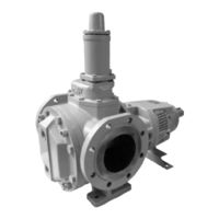
SPX Flow TG GP86-100 Instruction Manual (88 pages)
INTERNAL GEAR PUMPS
Brand:
SPX Flow
| Category:
Water Pump
| Size: 6 MB
Table of Contents
Table of Contents
3
1 Introduction
7
General
7
Reception, Handling and Storage
7
Reception
7
Handling
7
Storage
7
Safety
8
General
8
Pump Units
9
Pump Unit Handling
9
Installation
9
Before Commissioning the Pump Unit
10
Disassembly/Assembly of the Coupling Guard
10
Name Plate - CE Declaration of Conformity
10
Technical Conventions
11
2 Pump Description
12
Type Designation
12
3 General Technical Information
15
Pump Standard Parts
15
Operating Principle
15
Self-Priming Operation
16
Safety Relief Valve - Working Principle
16
Sound
16
General Performance
16
Main Characteristics
17
Pressure
18
Sound Level
18
Sound Level of a Pump Without Drive
18
The Sound Level of the Pump Unit
19
Influences
19
Material Options
20
Jacket Options
20
Electrical Heating
20
Internals
20
Bush Materials
20
Maximum Temperature of Internals
21
Operation under Hydrodynamic Lubrication Conditions
21
Maximum Torque of Pump Shaft and Rotor Material Combination
22
Mass Moment of Inertia
22
Axial and Radial Clearances
22
Extra Clearances
22
Play between Gear Teeth
23
Maximum Size of Solid Particles
23
Shaft Sealing
24
Packed Gland (no Lantern Ring)
24
Packing Ring Materials
24
Safety Relief Valve
25
Pressure
26
Heating
26
Safety Relief Valve - Relative Adjustment
26
Sectional Drawings and Part Lists
28
Single Safety Relief Valve
28
Heated Spring Casing
29
Double Safety Relief Valve
29
Installation
30
General
30
Location
30
Short Suction Line
30
Accessibility
30
Outdoor Installation
30
Indoor Installation
31
Stability
31
Drives
31
Starting Torque
31
Radial Load on Shaft End
32
Shaft Rotation for Pump Without Safety Relief Valve
32
Shaft Rotation for Pump with Safety Relief Valve
33
Suction and Discharge Pipes
34
Forces and Moments
34
Piping
34
Isolating Valves
35
Strainer
35
Secondary Piping
35
Drain Lines
35
Heating Jackets
36
Guidelines for Assembly
37
Transport of Pump Unit
37
Foundation Pump Unit
37
Variators, Gear Box, Gear Motors, Motors
37
Electric Motor Drive
37
Combustion Engines
38
Shaft Coupling
38
Guarding of Moving Parts
39
Electrical Heating
39
Instructions for Start-Up
40
General
40
Cleaning the Pump
40
Cleaning Suction Line
40
Venting and Filling
40
Tggp/
40
Checklist - Initial Start-Up
41
Start-Up
42
Shut-Down
42
Abnormal Operation
42
Trouble Shooting
43
Instructions for Re-Using and Disposal
45
Re-Use
45
Disposal
45
Maintenance Instructions
46
General
46
Preparation
46
Surroundings (on Site)
46
Tools
46
Shut-Down
46
Motor Safety
46
Conservation
46
External Cleaning
47
Electrical Installation
47
Draining of Fluid
47
Fluid Circuits
47
Electrical Heating
47
Specific Components
48
Nuts and Bolts
48
Plastic or Rubber Components
48
Flat Gaskets
48
Filter or Suction Strainer
48
Anti-Friction Bearings
48
Sleeve Bearings
49
Shaft Seal
50
Front Pull-Out
51
Back Pull-Out
51
Clearance Adjustment
51
Designation of Threaded Connections
52
Threaded Connection Rp (Example Rp 1/2)
52
Threaded Connection G (Example G 1/2)
52
4 Instructions for Assembly and Disassembly
53
General
53
Tools
53
Preparation
53
After Disassembly
53
Anti-Friction Bearings
54
General
54
TG GP2-25, TG GP3-32 and TG GP6-40 Disassembly
54
TG GP2-25, TG GP3-32 and TG GP6-40 Assembly
54
TG GP15-50 to TG GP360-150 Disassembly
55
TG GP15-50 to TG GP360-150 Assembly
55
Relief Valve
56
Disassembly
56
Assembly
56
Electrical Heating
57
General
57
Electrical Heating on the Pump Cover (in the Idler Pin)
57
Disassembly
57
Assembly
57
Electrical Heating Around Shaft Seal (in the Intermediate Casing)
58
Disassembly
58
Assembly
58
5 Sectional Drawings and Part Lists
59
TG GP2-25 to TG GP6-40
59
Hydraulic Part
60
Bearing Bracket
60
Flange Connection Options
60
Jacket Options
61
Jacket Option on Pump Cover
61
Jacket Option Around Shaft Seal
61
Seal Option: Packing Rings PO
62
TG GP15-50 to TG GP360-150
63
Hydraulic Part
64
Bearing Bracket
64
Jacket Options and Electrical Heating
65
Jacket on Pump Cover
65
Jacket Around the Shaft Seal
65
Electrical Heating on the Pump Cover (in the Idler Pin)
66
Electrical Heating Around Shaft Seal (in the Intermediate Casing)
67
Seal Options: Packing Rings PO
68
6 Dimensional Drawings
69
Standard Pump
69
TG GP2-25 to TG GP6-40
69
TG GP15-50 to TG GP360-150
70
Flange Connections
71
TG GP2-25 to TG GP6-40
71
TG GP15-50 to TG GP360-150
71
Jackets - Electrical Heating
72
Jackets TG GP2-25 to TG GP6-40
72
Jackets TG GP15-50 to TG GP360-150
73
Electrical Heating
74
Safety Relief Valves
75
Single Safety Relief Valve
75
Double Safety Relief Valve
75
Heated Safety Relief Valve
76
Bracket Support
77
Weights - Mass
77
Erpe-Mere, 1 April
78
Advertisement
Advertisement
Related Products
SPX Flow TG GP15-50
SPX Flow TG GP23-65
SPX Flow TG GP58-80
SPX Flow TG GP2-25
SPX Flow TG GP3-32
SPX Flow TG GP6-40
SPX Flow TG GM3-32
SPX Flow TG GM15-50
SPX Flow TG GM23-65
SPX Flow TG GM86-100
SPX Flow Categories
Water Pump
Control Unit
Dehumidifier
Power Tool
Water Filtration Systems
More SPX Flow Manuals
Login
Sign In
OR
Sign in with Facebook
Sign in with Google
Upload manual
Upload from disk
Upload from URL