Table of Contents
Advertisement
Thank you for purchasing HD30 series AC drives (inverter) manufactured by
Shenzhen Hpmont Technology Co., Ltd.
This User Manual describes how to use HD30 series inverters and their
installation wiring, parameter setting, troubleshooting and daily maintenance etc.
Before using the product, please read through this User Manual carefully. In
addition, please do not use this product until you have fully understood safety
precautions.
Note:
Preserve this Manual for future.
Due to product upgrade or specification change, and for the purpose of improving
the convenience and accuracy of this manual, this manual's contents may be
modified.
If you need the User Manual due to damage, loss or other reasons, please contact
the regional distributor of our company or directly contact our company Technical
Service Center.
For the first time using, the user should carefully read this manual.
If you still have some problems during use, please contact our company Technical
Service Center.
Telephone: 4008-858-959 or 189 4871 3800
The product warranty is on the last page of this Manual, please preserve it for future.
FOREWORD
Advertisement
Table of Contents

Related Manuals for hpmont HD30 Series


Summary of Contents for hpmont HD30 Series
- Page 1 Thank you for purchasing HD30 series AC drives (inverter) manufactured by Shenzhen Hpmont Technology Co., Ltd. This User Manual describes how to use HD30 series inverters and their installation wiring, parameter setting, troubleshooting and daily maintenance etc. Before using the product, please read through this User Manual carefully. In addition, please do not use this product until you have fully understood safety precautions.
- Page 2 Connection with peripheral devices Three-phase AC power supply MCCB Contactor AC input reactor EMI filter Braking resistor (optional) HD30 series inverter DC reactor (optional) Ground connection EMI filter AC output reactor Motor Ground connection...
-
Page 3: Table Of Contents
CONTENTS Chapter 1 Safety Information and Precautions ................1 1.1 Safety Definition ....................... 1 1.2 About Motor and Load ...................... 1 1.3 Installation Limitation ......................2 Chapter 2 Product Information ...................... 5 2.1 Model Code Explanation ....................5 2.2 Nameplate ........................5 2.3 Specifications ........................ - Page 4 4.5.3 SCI Communication Terminal Description ............28 4.5.4 Control Terminal Connection ................29 Chapter 5 Operation Instructions ....................35 5.1 Function Description ....................... 35 5.1.1 Inverter Run Command Source ................35 5.1.2 Inverter Frequency Setting Source ..............35 5.1.3 Inverter Status ....................36 5.1.4 Inverter Operation Mode ..................
- Page 5 6.2.19 Group F18 Display Control Parameters ............97 6.2.20 Group F19 Function-boost Parameters ............99 6.2.21 Group F20 Protection of Fault Parameters ............. 105 6.2.22 Group F21 Reserved ..................108 6.2.23 Group F22 Reserved ..................108 6.2.24 Group F23 PWM Control Parameters ............. 109 6.3 Group U User Menu Mode Display Parameters ............
- Page 7 Safety Information and Precautions Product Information Mechanical Installation Electrical Installation Operation Instructions Function Introduction Troubleshooting Maintenance Parameters User Menu Setting Table Communication Protocol...
-
Page 9: Chapter 1 Safety Information And Precautions
1.2 About Motor and Load Compared to the standard frequency operation The HD30 series inverters are voltage-type frequency inverter and their output is PWM wave with certain harmonic wave. Therefore, the temperature, noise and vibration of the motor will be a little higher than that at standard frequency operation. -
Page 10: Installation Limitation
60% rated value. Lightning surge protection The inverter internal design has lightning surge overcurrent protection circuit, and has certain self-protection capacity against the lightning. ―2― HD30 Series Inverters User Manual... - Page 11 Figure1-1 is the derating curve of the inverter rated current and the altitude. Inverter’s rated current 100% Altitude(m) 1000 4000 Figure1-1 Derating curve of inverter rated current and altitude ―3― HD30 Series Inverters User Manual...
-
Page 13: Chapter 2 Product Information
Inverter’s model MODEL: HD30-4T5P5G/7P5P POWER: 5.5/7.5kW Adaptive motor Input specification INPUT: 3PH 380-460V 15/19A 50/60Hz Output specification OUTPUT: 8.5/11kVA 0-460V 13/17A 0-400Hz Software version Version: 1.00 S/N: Serial number Barcode Shenzhen Hpmont Technology Co., Ltd ―5― HD30 Series Inverters User Manual... -
Page 14: Specifications
Internal water and wastewater applications module which should be with wastewater HD30-WIO applications Inverter built-in MODBUS communication protocol. Compatible Available options: multi-communication PROFIBUS bus module, compatible with PROFIBUS protocol; protocol DeviceNet bus module, compatible with DeviceNet protocol; ―6― HD30 Series Inverters User Manual... - Page 15 Digital output DO1, DO2 DO2 can be selectable for high-frequency output 1 output Programmable relay R1A/R1B/R1C: contact rating 250VAC/3A or 30VDC/1A output (it can be extended to 4 outputs with HD30-EIO) SCI communication RS-485 interface ―7― HD30 Series Inverters User Manual...
-
Page 16: Ratings
Power units Energy depletion feedback unit (HDRU) 2.4 Ratings Rated capacity Rated input Rated output Model HD30- Motor power(kW) (kVA) current(A) current(A) Single/three-phase power supply: 200-240V, 50/60Hz 2D0P4G 2D0P7G 10.5 0.75 2D1P5G 18.5 2D2P2G 24.1 ―8― HD30 Series Inverters User Manual... - Page 17 250/280 385/430 380/426 200/220 4T220G/250P 280/309 430/475 426/470 220/250 4T250G/280P 309/349 475/535 470/530 250/280 4T280G/315P 349/398 535/609 530/600 280/315 4T315G/355P 398/434 609/664 600/660 315/355 4T355G/400P 434/494 664/754 660/750 355/400 4T400G/450P 494/560 754/852 750/830 400/450 ―9― HD30 Series Inverters User Manual...
-
Page 18: Parts Of Inverter
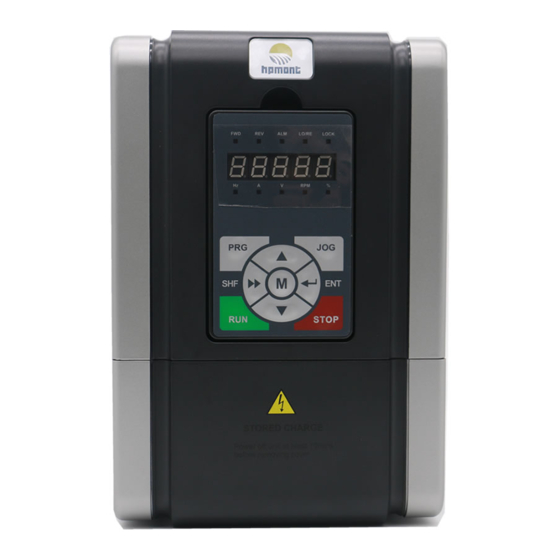
Chapter 2 Product Information Shenzhen Hpmont Technology Co., Ltd 2.5 Parts of Inverter Fan cover Mounting hole Mounting hole Upper cover Bottom enclosure LO/RE LOCK Nameplate Display panel Certification Lower cover Middle enclosure ―10― HD30 Series Inverters User Manual... -
Page 19: Chapter 3 Mechanical Installation
To achieve good cooling efficiency, install the inverter perpendicularly and always provide the following space to allow normal heat dissipation. The requirements on mounting space and clearance are shown in Figure 3-1and Table 3-1. ―11― HD30 Series Inverters User Manual... - Page 20 L O /R E L O C K R P M F W D R E V A L M L O /R E L O C K R P M Figure 3-2 Installation of several inverters ―12― HD30 Series Inverters User Manual...
-
Page 21: Dimensions And Mounting Size
Shenzhen Hpmont Technology Co., Ltd Chapter 3 Mechanical Installation 3.4 Dimensions and Mounting Size 4-Ød LO/RE LOCK Figure1 4-Ød LO/RE LOCK Figure2 ―13― HD30 Series Inverters User Manual... - Page 22 4T011G/015P 2T7P5G 4T015G/018P 4T018G/022P 2T011G 2T015G 2T018G 4T022G/030P 4T030G/037P 2T022G 2T030G 2T037G 4T037G/045P 4T045G/055P 4T055G/075P In the Table 3-2, the mm and the Kg are respectively units of the size and the gross weight. ―14― HD30 Series Inverters User Manual...
-
Page 23: Display Panel Installation And Dismantle
Second, take out of the display panel according to the direction 2. F W D R E V A L M L O /R E L O C K R P M STOP Figure 3-4 Dismantle of the display panel ―15― HD30 Series Inverters User Manual... -
Page 24: Display Panel Mounting Seat Size
The installation dimensions of the display panel are shown as following. The unit is mm. ± 0.2 Display panel seat mounting hole size LO/RE LOCK +0.1 76.5 Figure 3-5 Installation dimensions of display panel seat ―16― HD30 Series Inverters User Manual... -
Page 25: Chapter 4 Electrical Installation
The inverter DC bus terminals must not be short-circuited. 4.2 Selection of Main Circuit Peripheral Devices Please refer to the Table 4-1 for the recommended specifications. Table 4-1 HD30 series inverters I/O wiring specification Input Protection Main Circuit (mm Control... - Page 26 ≥0.5 4T280G/315P 185*2 185*2 ≥0.5 4T315G/355P 150*3 150*3 ≥0.5 4T355G/400P 150*4 150*4 ≥0.5 4T400G/455P 1000 1000 150*4 150*4 Remarks: *2, *3, *4 respectively represent “2, 3 and 4 main circuit cables are in parallel”. ―18― HD30 Series Inverters User Manual...
-
Page 27: Main Circuit Terminals And Wiring
Ensure that AC supply voltage is the same as inverter’s rated input voltage. 4.3.1 Terminals Description L1 L2 MOTOR POWER Figure 4-1 Main circuit terminal layout of 5.5kW or below model L1 L2 (+) (-) MOTOR POWER Figure 4-2 Main circuit terminal layout of 7.5-55kW model ―19― HD30 Series Inverters User Manual... -
Page 28: Wiring Terminals
During trial operation, make sure the inverter runs forward when the forward command is enabled. If not, switch any two of the output terminals (U, V, W) or modify the setting of parameter F00.17 to change the inverter’s direction. ―20― HD30 Series Inverters User Manual... -
Page 29: Meet Emc Requirement Of Installation
IEC/61800-3 (VVVF drive system part 3: EMC specifications and test methods) are identical to the national standards GB/T12668.3. HD30 Series Inverters are designed and produced according to the requirements of IEC/61800-3. Please install the inverter as per the description below so as to achieve good electromagnetic compatibility (EMC). -
Page 30: Wiring Requirement
Normally, the control cables must use the shielded cables and the shielding metal net must be connected to the metal enclosure of the inverter by cable clamps as shown in Figure 4-7. Enclosure Enclosure Figure 4-7 Correct connection of the shielded cable ―22― HD30 Series Inverters User Manual... -
Page 31: Wiring Motor
Other devices HD30 Other devices Dedicated earthing pole Sharing earthing pole (optimal) (good) Figure 4-8 Recommended earthing method Other devices HD30 Other devices HD30 Sharing earthing pole (not so good) Figure 4-9 Avoided earthing method ―23― HD30 Series Inverters User Manual... -
Page 32: Emi Filter
4.4.6 Conduction, Radiation and Radio Frequency Interference Countermeasures EMI of the inverter The inverter’s operating theory means that some EMI is unavoidable. The inverter is usually installed in a metal cabinet which normally little affects the instruments outside the metal cabinet. ―24― HD30 Series Inverters User Manual... -
Page 33: Input And Output Reactor
Generally speaking, when the length of the cable between inverter and motor is more than 100m, it will cause leakage current and inverter tripping. It suggests that the user should consider installing an AC output reactor. ―25― HD30 Series Inverters User Manual... -
Page 34: Control Terminals And Wire Connection
The positions of control terminal, wire jumper and SCI communication port in the control PCB are shown in Figure 4-12. Wire jumper Wire jumper Control terminal Wire jumper Wire jumper communication port Figure 4-12 Positions of control terminal, wire jumper and SCI communication port in the control PCB ―26― HD30 Series Inverters User Manual... -
Page 35: Control Terminal Description
It is equal to DO1 while selecting open collector output; Select pulse frequency output, max-frequency 50kHz Programmable output, contact rating: 250VAC/3A or R1A/ R1B/ Relay contact Relay output 30VDC/1A output R1B,R1C: normally closed; R1A,R1C: normally open ―27― HD30 Series Inverters User Manual... -
Page 36: Wire Jumper Description
4.5.3 SCI Communication Terminal Description 1 2 3 4 5 6 7 8 RJ45 Figure 4-14 SCI communication terminal Table 4-6 SCI communication terminal description Communication port pin Communication 485+ 485- Reserved port signal ―28― HD30 Series Inverters User Manual... -
Page 37: Control Terminal Connection
Multi-function input terminal 6 Programmable relay output Digital ground Analogue input 1 Analogue output channel 1 Analogue input 2 Analogue output channel 2 Analogue ground Analogue ground Figure 4-15 HD30 control circuit connection diagram ―29― HD30 Series Inverters User Manual... - Page 38 2.If the external power supply is used, the connection is as shown in Figure 4-17. (Note that the SEL and the P24 are not short-circuited) + 24V + 3.3V Current 12-30V DI1...DI6 Figure 4-17 Dry contact connection when using external power supply ―30― HD30 Series Inverters User Manual...
- Page 39 2. If the external power supply is used, the PNP connection is as shown in Figure 4-19. (Note that the SEL and the P24 are not short-circuited) + 24V DC 12-30V + 3.3V + 3.3V External controller Figure 4-19 PNP input connection when using external power supply ―31― HD30 Series Inverters User Manual...
- Page 40 PNP transistor in the external controller is as shown in Figure 4-21. (Note that the SEL and the P24 are not short-circuited) + 24V + 3.3V + 3.3V External controller Figure 4-21 PNP signal input connection when using internal 24V power supply ―32― HD30 Series Inverters User Manual...
- Page 41 The connections are as shown in Figure 4-23. + 24V + 24V R: 10KΩ resistor f: digital frequency counter 12-30V Using the internal 24V power supply Using the external power supply Figure 4-23 DO2 terminal connection ―33― HD30 Series Inverters User Manual...
-
Page 43: Chapter 5 Operation Instructions
5 master setting sources (set by F00.10) and 6 auxiliary setting sources (set by F19.00). Note: The frequency will be set by master setting source if the auxiliary is the same as the master setting source. ―35― HD30 Series Inverters User Manual... -
Page 44: Inverter Status
Motor parameters auto-tuning: If the inverter receives the run command by the function parameter F08.06/F13.07 set as 1 or 2, the inverter will enter motor parameters auto-tuning status. Then enters stop status if the auto-tuning process is completed. ―36― HD30 Series Inverters User Manual... -
Page 45: Inverter Operation Mode
PLC function can be disabled by a digital input multi-functional terminal (No. 30 function). Wobble operation: If the wobble operation is enabled (F07.00 = 1), the inverter will operate in the preset operating parameter mode (see explanation of Group F07) to implement wobble operation. ―37― HD30 Series Inverters User Manual... -
Page 46: Operating Instructions
Set certain function by F00.12 Increment key Increase value or parameter Decrement key Decrease value or parameter SHF shift key Selecting display parameter and shift bit ENT enter/confirm key Enter lower menu or confirm saving the data ―38― HD30 Series Inverters User Manual... - Page 47 Lightless: The unit of the current function parameter or status display parameter is not % The indicator has three statuses: Lightless, lighting, flashing statuses are shown as following: It means lightless indicator; It means lighting indicator; It means flashing indicator. ―39― HD30 Series Inverters User Manual...
-
Page 48: Display Status
Figure 5-2. Other parameters can be displayed by pressing (defined by parameter F18.08-F18.13). LO/RE LOCK Figure 5-2 Display status of the display panel ―40― HD30 Series Inverters User Manual... - Page 49 First-level menu LO/RE LOCK LO/RE LOCK Second-level menu Second-level menu LO/RE LOCK LO/RE LOCK Third-level menu Third-level menu LO/RE LOCK LO/RE LOCK LO/RE LOCK Fourth-level menu Third-level menu Third-level menu Figure 5-4 Four-level operation process ―41― HD30 Series Inverters User Manual...
- Page 50 If the inverter detects a fault signal, the display panel will enter the fault alarm status and flashing display the fault code, as shown in Figure 5-6. You can enter Group F20 (F20.21-F20.37) to check the fault history. LO/RE LOCK Figure 5-6 Fault alarm status ―42― HD30 Series Inverters User Manual...
- Page 51 LO/RE LOCK LO/RE LOCK Power on initialization Display panel self-check success Parameter auto-tuning LO/RE LOCK LO/RE LOCK LO/RE LOCK Power on initialization Display panel self-check error Restore factory setting Figure 5-7 Special display status ―43― HD30 Series Inverters User Manual...
-
Page 52: Display Panel Operation Examples
• The function parameter can’t be modified, such as the actual detected parameters or recorded parameters etc. • Only when the inverter stops can it modify the function parameter. • Only input the correct password can it edit the function parameter due to the valid password. ―44― HD30 Series Inverters User Manual... - Page 53 LO/RE LOCK LO/RE LOCK LO/RE LOCK Third-level menu Fourth-level menu Input correct password LO/RE LOCK LO/RE LOCK 1.5 seconds later Third-level menu Unlock password success Figure 5-10 Operation of unlocking user’s password ―45― HD30 Series Inverters User Manual...
- Page 54 “F01.01”, you can clear the user’s password according to Figure 5-12. LO/RE LOCK LO/RE LOCK LO/RE LOCK Third-level menu Fourth-level menu Third-level menu LO/RE LOCK LO/RE LOCK 1.5 seconds later Third-level menu Clear password success Figure 5-12 Operation of clearing user’s password ―46― HD30 Series Inverters User Manual...
- Page 55 Shenzhen Hpmont Technology Co., Ltd Chapter 5 Operation Instructions Display panel self-checking The display panel of the HD30 series Inverters has self-checking function which facilitates periodic inspection for itself and keys. In stop status, the self-checking function can be enabled by pressing simultaneously for 2-3 seconds.
-
Page 56: Initial Power On
After checking the wiring and mains supply voltage, switch on the circuit breaker and the inverter will be initialization. The display panel will display as shown in Figure 5-17. LO/RE LOCK LO/RE LOCK LO/RE LOCK Firstly displaying initialization Then displaying Finish inverter initialization Figure 5-17 Display initialing display panel ―48― HD30 Series Inverters User Manual... -
Page 57: Chapter 6 Function Introduction
Group F20 Protection of Fault Parameters (on pages 105-108) Group F21 Reserved Group F22 Reserved Group F23 PWM Control Parameters (on pages 109-109) User Setting Parameters: Group U User Menu Mode Display Parameters (on pages 109-110) Manufacturer Function Parameters (on page110) ―49― HD30 Series Inverters User Manual... -
Page 58: Group D: Display Parameters
Rated current of the inverter Display the rated current of the inverter. 【actual value】 d00.09 Extension function of the inverter Display the extension function of the inverter. 0: Standard inverter. 1: Water and wastewater applications (with HD30-WIO). ―50― HD30 Series Inverters User Manual... - Page 59 Display the sequence phase of the three-phase input. • 0: Positive sequence: L1(R) preceding L2(S) preceding L3(T). • 1: Negative sequence: L1(R) preceding L3(T) preceding L2(S). 【actual value】 d00.20 Output voltage Display output voltage. 【actual value】 d00.21 Output current ―51― HD30 Series Inverters User Manual...
- Page 60 0A and 10.00V corresponds to 20mA. 【actual value】 d00.38 High-speed output pulse frequency Display high-speed output pulse frequency(Hz). 【actual value】 d00.39 Heatsink temperature Display heatsink temperature. d00.40 Reserved d00.41 Reserved d00.42 Reserved ―52― HD30 Series Inverters User Manual...
- Page 61 Note: Only when using the corresponding extension options can the RLY2-RLY10 are enabled. RLY2-RLY4 are enabled with HD30-EIO; RLY2-RLY10 are enabled with HD30-WIO. 【actual value】 d00.52 MODBUS communication status Display MODBUS communication status. 0: Normal. 1: Communication timeout. 2: Incorrect data frame head. ―53― HD30 Series Inverters User Manual...
-
Page 62: Group D01 Reserved
Pump 3 status 0【0】 d02.04 Pump 4 status 0【0】 d02.05 Pump 5 status 0【0】 d02.06 Pump 6 status 0【0】 d02.07 Pump 7 status 0【0】 Display the pump status. 0: At rest. 1: Run. 2: Fault. ―54― HD30 Series Inverters User Manual... -
Page 63: Group F: General Function Parameters
0: Digital setting. Set the upper limit frequency by F00.08. 1: Analogue input AI setting. See Group F16. 2: Terminal pulse setting. F16.17 sets the max. pulse input frequency according to F00.06 (inverter max. output frequency). ―55― HD30 Series Inverters User Manual... - Page 64 0.00-upper limit 【50.00Hz】 When F00.10 = 0 or 1, F00.13 start to set the initial frequency value. F00.14 UP/DOWN digital setting control 00-11【00】 Only when F00.11 = 0 or 1 will it be valid. ―56― HD30 Series Inverters User Manual...
- Page 65 Dead time of direction switch 0.0-3600.0s【0.0】 Frequency F00.19 defines the dead time of direction switch, namely, F00.19 the time of zero-frequency output in the process of Time Forward direction switch shown as the right figure. Reverse ―57― HD30 Series Inverters User Manual...
-
Page 66: Group F01 Protection Of Parameters
1: Upload the current function code settings to the display panel EEPROM parameter 1. 2: Upload the current function code settings to the display panel EEPROM parameter 2. Note: F01.00, F01.02, F01.03, Group F08, F13.01-F13.15, F19.24-F19.25, F20.21-F20.37 and Group y do not upload or download. ―58― HD30 Series Inverters User Manual... -
Page 67: Group F02 Run/Stop Control Parameters
But it is disabled in the process of direction switch. F02.01 Starting delay time 0.00-10.00s【0.00】 When the inverter receives the run command, it will wait for the delay time set by F02.01 and then start running. ―59― HD30 Series Inverters User Manual... - Page 68 Set the motor injection current. F02.09 Acc./Dec. time of the speed search 1.0-50.0s【5.0】 Frequency rate of decline follows the deceleration time at speed searching. F02.06 = 1 (speed searching based on current) is enabled. ―60― HD30 Series Inverters User Manual...
- Page 69 F02.18 = 0.00s, there is no DC braking F02.18 process at stop. F02.17 Run command • Only when F02.13 = 2 will F02.16- A: running frequency reaches F02.16 F02.18 be enabled. B: start to apply DC braking value ―61― HD30 Series Inverters User Manual...
-
Page 70: Group F03 Acceleration/Deceleration Parameters
When the running frequency is smaller than the F03.10 setting, it will decelerate according to deceleration time 2; Otherwise it will decelerate according to deceleration time 1. • When use terminals to select acceleration/deceleration time (set multi-function terminal as ―62― HD30 Series Inverters User Manual... -
Page 71: Group F04 Process Pid Control
It defines the process PID regulator reference. When F04.01 = 0 (digital reference), it is enabled. F04.04 Proportional gain (P) 0.00-10.00【2.00】 F04.05 Integral time (I) 0.00-10.00s【1.00】 F04.06 Integral upper limit 0.00-upper limit【50.00】 F04.07 Differential time (D) 0.00-10.00s【0.00】 F04.08 Differential amplitude limit value 0.00-upper limit【20.00】 ―63― HD30 Series Inverters User Manual... - Page 72 It is recommended to disable the integral regulation when the frequency reaches the upper or lower limit on condition that fast response is needed. F04.17 PID output filter time 0.01-10.00s【0.05】 It defines the filtering time of process PID output. ―64― HD30 Series Inverters User Manual...
-
Page 73: Group F05 External Reference Curve Parameters
Line 1, line 2 and polyline can independently achieve positive and negative characteristics as shown in following figure. • If set the curve’s minimum reference the same as maximum reference, it must be a line. The default frequency is the corresponding frequency of the curve minimum reference. ―65― HD30 Series Inverters User Manual... - Page 74 • Frequency setting is uncontinuous, while frequency output is continuous. F05.21 Jog operation frequency digital setting 2 0.00-upper limit【5.00Hz】 When select jog operation 2 through terminal, set the jog frequency operation according to F05.21. ―66― HD30 Series Inverters User Manual...
-
Page 75: Group F06 Ms Speed And Simple Plc
0: Stop after single cycle operation. The inverter stops automatically after one operating cycle. It will start only after receiving the run command next time. Stop T7 T8 T9 T11 T12 T13 T14 Run command ―67― HD30 Series Inverters User Manual... - Page 76 • It will continue to operate at the recorded Time = the operated time = the rest frequency upon restart, as shown in figure. ―68― HD30 Series Inverters User Manual...
- Page 77 • If the direction is not set, the inverter will run in the direction according to last step. Hundreds: Acceleration/deceleration time selection of PLC at different steps • 0: Acceleration/deceleration time 1. • 1: Acceleration/deceleration time 2. • 2: Acceleration/deceleration time 3. • 3: Acceleration/deceleration time 4. ―69― HD30 Series Inverters User Manual...
- Page 78 F06.42, F06.44, F06.46 define the running time of PLC at different steps. • When set the running time to 0 at some step, it means that the PLC function of this step is disabled. ―70― HD30 Series Inverters User Manual...
-
Page 79: Group F07 Wobble Operation Parameters
(F07.02). Tens: Wobble operation amplitude. Refer to parameter F07.04. • 0: Relative to the wobble central frequency. • 1: Relative to the maximum output frequency. ―71― HD30 Series Inverters User Manual... - Page 80 Relative to wobble operation cycle of the F07.06, F07.07 defines the rising and the falling time of wobble operation and their unit is s. Rising time of wobble operation = F07.06 × F07.07. • Falling time of wobble operation = F07.06 × (1 - F07.07). • ―72― HD30 Series Inverters User Manual...
-
Page 81: Group F08 Asynchronous Motor 1 Parameters
Hinterher the motor will start rotating, accordingly mutual inductance and idling exciting inductance will be measured automatically. All the measured values above will be saved respectively in F08.07, F08.08, ―73― HD30 Series Inverters User Manual... -
Page 82: Group F09 V/F Control Parameters
2: 1.2 exponential curve. Shown as curve 2 in the figure. Output freq. 1/3 x F08.03 F08.03 3: 1.7 exponential curve. Shown as curve 3 in the figure. 4: User-defined curve. F09.01 V/f frequency value F3 of motor 1 F09.03-F08.03【0.00Hz】 ―74― HD30 Series Inverters User Manual... - Page 83 F09.08 is relative to percentage of motor’s rated F09.08max = 50% F08.03 frequency (F08.03). F09.09 Slip compensation gain of motor 1 0.0-300.0%【100.0】 F09.10 Slip compensation filter time of motor 1 0.01-10.00s【0.10】 F09.11 Slip compensation limitation of motor 1 0.0-250.0%【200.0】 ―75― HD30 Series Inverters User Manual...
- Page 84 This function is used to damp oscillation when output current is continually unstable. • This function helps to keep the motor running smoothly through correctly adjusting the setting of F09.16. F09.17 Reserved F09.18 Reserved ―76― HD30 Series Inverters User Manual...
-
Page 85: Group F10 Motor 1 Vector Control Speed-Loop Parameters
There is not the speed-loop differential when F10.07 = 0. F10.08 Speed-loop output filter time of motor 1 0.000-1.000s【0.020】 It is used to filter the output of ASR regulator. • When F10.08 = 0, the speed-loop filter is disabled. ―77― HD30 Series Inverters User Manual... -
Page 86: Group F11 Reserved
0.0-999.9A【dependent on inverter model】 5.5KW or below 0.00-99.99A【dependent on inverter model】 F13.04 Rated frequency of motor 2 1.0-400.0Hz【50.0】 F13.05 Rated speed of motor 2 1-24000rpm【1440】 F13.06 Power factor of motor 2 0.001-1.000【dependent on inverter model】 ―78― HD30 Series Inverters User Manual... - Page 87 0.0-250.0%【200.0】 F13.28 Compensation constant of motor 2 0.1-25.0s【2.0】 F13.29 Reserved F13.30 AVR (automatic voltage regulation) function of motor 2 0-2【2】 F13.31 Oscillation-suppression mode of motor 2 0,1【1】 F13.32 Oscillation-suppression coefficient of motor 2 0-200【50】 ―79― HD30 Series Inverters User Manual...
- Page 88 F13.47 Motor torque limitation when motor 2 is reverse F13.48 Recreated torque limitation when motor 2 is forward F13.49 Recreated torque limitation when motor 2 is reverse F13.50 Reserved F13.51 Reserved F13.52 Reserved ―80― HD30 Series Inverters User Manual...
-
Page 89: Group F14 Reserved
8: AI to be the frequency source. • If the setting is 8, the frequency reference source can be forcibly switched to AI analogue setting. • The priority of frequency sources is shown below: ―81― HD30 Series Inverters User Manual... - Page 90 • The inverter can realise the switch between setting frequency and multi-step frequency through one terminal function. • Refer to the below table and figure. K1 to terminal 1, K2 to terminal 2, K3 to terminal 3, K4 to terminal 4. ―82― HD30 Series Inverters User Manual...
- Page 91 • Increase or decrease rate is determined by F15.12. The function refers to below table. • This terminal is enabled when F00.10=1 (terminal digital setting) or F19.00=2 (terminal digital setting). ―83― HD30 Series Inverters User Manual...
- Page 92 (except stop command) and maintain operation at the current speed. • The function is disabled in the process of deceleration to stop. 30: Pausing PLC operation. If the setting is 30, this terminal is used to pause the PLC operation. ―84― HD30 Series Inverters User Manual...
- Page 93 F15.17. • Once the inverter receives the fault signal, it will display external fault. • The fault signal has two input modes: normally-open and normally-closed input. ―85― HD30 Series Inverters User Manual...
- Page 94 Negative logic: When multi-function input terminals are connected to corresponding common port, this logic is disabled. Otherwise the logic is enabled. Hundreds Tens Units Bit11 Bit10 Bit9 Bit8 Bit7 Bit6 Bit5 Bit4 Bit3 Bit2 Bit1 Bit0 ―86― HD30 Series Inverters User Manual...
- Page 95 Terminal operating selection due to fault of external 0-3【0】 equipment When there is fault of external equipment, it can select protection. 0: Coast to stop. 1: Emergency stop. 2: Decelerate to stop. 3: Continue to run. ―87― HD30 Series Inverters User Manual...
- Page 96 • When F07.00 = 1 (using the wobble function), this terminal function is enabled. Running frequency Before limiting amplitude Upper limit of frequency Wobble frequency After limiting amplitude Central frequency Lower limit of frequency F00.09 Time Output signal Limitation of upper/lower limits of wobble frequency ―88― HD30 Series Inverters User Manual...
- Page 97 • Power supply forward: L1 (R) preceding L2 (S) preceding L3 (T). 35-37: Reserved. 38: High-frequency output (only DO2). DO2 can be selected as high-frequency output. • Refer to parameter F16.21. Note: Only when using HD30-EIO will F15.21-F15.23 be enabled. ―89― HD30 Series Inverters User Manual...
- Page 98 F15.26 F15.27 FAR range 0.10-100.00Hz【2.50】 Output The pulse signal will be output if the inverter’s output frequency is within the FAR range. As Preset shown in the right figure. frequency Detecting range Time Time ―90― HD30 Series Inverters User Manual...
- Page 99 F15.35 FDT2 lag 0.00-F00.06【1.00Hz】 Refer to parameters F15.31 and F15.32. F15.36 Preset operating time 0-65535h【0】 When the total operating time reaches the preset operating time (F15.36), the inverter will output an indicating signal (500ms). ―91― HD30 Series Inverters User Manual...
-
Page 100: Group F16 Analogue I/O Terminal Parameters
2: Frequency setting source. • When F00.10 = 3 (frequency setting source is set by analogue input), the setting frequency will be set by the input voltage value corresponding to the analogue source which selects this function. ―92― HD30 Series Inverters User Manual... - Page 101 Analogue input AI1 filtering time 0.01-10.00s【0.05】 F16.10 Analogue input AI2 filtering time F16.13 Analogue input AI3 filtering time F16.16 Analogue input AI4 filtering time When select AI1-AI4 inputs as open-loop frequency setting source, the relationship between the ―93― HD30 Series Inverters User Manual...
- Page 102 14: AI1 input (0-10V). 15: AI2 input (-10-10V / 0-20mA). 16: AI3 input (-10-10V / 0-20mA). 17: AI4 input (-10-10V / 0-20mA). 18,19: Output frequency, reference frequency (- 1 times-1 times maximum output frequency). ―94― HD30 Series Inverters User Manual...
- Page 103 F16.24 Analogue output AO2 bias -100.0-100.0%【0.0】 F16.25 Analogue output AO2 gain 0.0-200.0%【100.0】 Refer to parameters F16.22 and F16.23. F16.26 DO2 maximum output pulse frequency 0.1-50.0kHz【10.0】 It defines the DO2 terminal allowable maximum output frequency. ―95― HD30 Series Inverters User Manual...
-
Page 104: Group F17 Sci Communication Parameters
In the communication command setting mode, F17.08 will define the action selection when communication peripheral device fault is alarmed. 0: Coast to stop. 1: Emergency stop. 2: Decelerate to stop. 3: Continue to run. ―96― HD30 Series Inverters User Manual... -
Page 105: Group F18 Display Control Parameters
DC braking Reserved Bit1&Bit0: Acceleration/ Deceleration/ Constant speed Hundreds Reserved Speed limitation Reserved auto-tuning Thousands Reserved Reserved Stall overcurrent Stall overvoltage 4: Master setting frequency source. 5: Master setting frequency. 6: Auxiliary setting frequency. ―97― HD30 Series Inverters User Manual... - Page 106 44: Output terminal status. • Bit0-Bit11 corresponding to DO1, DO2, RLY1-RLY10. 45: MODBUS communication status. 46: Actual length. 47: Total length. 48: Total time at power on (hour). 49: Total time at running (hour). ―98― HD30 Series Inverters User Manual...
-
Page 107: Group F19 Function-Boost Parameters
6.2.20 Group F19 Function-boost Parameters Frequency auxiliary setting sources (F19.00-F19.06) The multi-step frequency of HD30 series inverters is the result of both master setting frequency and auxiliary setting frequency. F19.00 defines the auxiliary frequency setting sources. When the auxiliary frequency setting source is the same as the master frequency setting source (except analogue setting), the auxiliary frequency setting source will be disabled. - Page 108 This function is used in the application that several inverters drive one motor. The function can make the inverters share the load equally. When the load of one inverter is heavier, this inverter will reduce its output frequency to shed part of the ―100― HD30 Series Inverters User Manual...
- Page 109 F19.11 Action selection at setting frequency is lower than 0-3【0】 zero-frequency threshold 0: Run according to frequency command. 1: Holding stop, no output. 2: Run according to zero-frequency threshold. 3: Run according to zero-frequency. ―101― HD30 Series Inverters User Manual...
- Page 110 F19.17 and then start operation automatically. F19.17 Delay time for restart after power failure 0.00-10.00s【2.00】 ―102― HD30 Series Inverters User Manual...
- Page 111 • If the setting is too big, the frequency will change too sharply and therefore, the inverter may be in generating status for a long time, which may result in overvoltage protection. ―103― HD30 Series Inverters User Manual...
- Page 112 F19.27 or changed to F19.27 < F19.26. Otherwise the inverter can’t be started. Name Description Range【factory setting】 F19.26 Preset length 0-65535m【0】 F19.27 Actual length 0-65535m【0】 F19.28 Length ratio 0.001-30.000【1.000】 F19.29 Length checking coefficient 0.001-1.000【1.000】 ―104― HD30 Series Inverters User Manual...
-
Page 113: Group F20 Protection Of Fault Parameters
Overload pre-alarm detection time 0.0-60.0s【5.0】 F20.02 defines the time during which the inverter output current exceeds overload pre-alarm detection threshold (F20.01). If the status remains after overload pre-alarm detection time (F20.02), the inverter will output pre-alarm signal. ―105― HD30 Series Inverters User Manual... - Page 114 When the inverter detects certain output current not hit the preset detection reference (F20.10) and exceed the preset detection time (F20.11), the inverter will perform output phase loss alarm (E0016). • When F20.10 or F20.11 is set to 0, the inverter will not detect output phase loss fault. ―106― HD30 Series Inverters User Manual...
- Page 115 When F20.19 = 0, it means “auto reset” is disabled and the protective device will be activated in case of fault. • If no other fault is detected within 5 minutes, the auto reset times will be automatically cleared. • On condition of external fault reset, auto reset time will be cleared. ―107― HD30 Series Inverters User Manual...
-
Page 116: Group F21 Reserved
Interval of third latest fault F20.34 Type of second latest fault F20.35 Interval of second latest fault F20.36 Type of first latest fault F20.37 Interval of first latest fault 6.2.22 Group F21 Reserved 6.2.23 Group F22 Reserved ―108― HD30 Series Inverters User Manual... -
Page 117: Group F23 Pwm Control Parameters
User menu map of setting 6 U00.12 User menu map of setting 7 U00.14 User menu map of setting 8 U00.16 User menu map of setting 9 U00.18 User menu map of setting 10 ―109― HD30 Series Inverters User Manual... -
Page 118: Group Y Manufacturer Function Parameters
The setting value of map 15 U00.31 The setting value of map 16 6.4 Group y Manufacturer Function Parameters The Group y is the manufacturer parameters group for debugging at the factory before delivery. ―110― HD30 Series Inverters User Manual... -
Page 119: Chapter 7 Troubleshooting
Chapter 7 Troubleshooting Chapter 7 Troubleshooting HD30 series inverter has inbuilt protective and warning self-diagnostic functions. If a fault occurs, the fault code will be displayed on the display panel. At the same time, fault relay acts, accordingly the inverter stops output and the motor coasts to stop. - Page 120 E0017 Inverter overload or torque boost leads to over • Please set start mode to be current speed tracking • Instant power-off occurs, the • Please check mains supply running motor is restarted voltage ―112― HD30 Series Inverters User Manual...
- Page 121 Please seek technical support • Analogue input circuit fault • Please check the connection PID feedback • Analogue setting signal is E0027 out of limiting bigger than the lower limit • Please seek technical support ―113― HD30 Series Inverters User Manual...
- Page 122 Please correctly set the • Disconnected or not well E0029 communication communication format and the connected error baud rate • Communication setting error • Send the data according to • Communication data error MODBUS protocol ―114― HD30 Series Inverters User Manual...
-
Page 123: Chapter 8 Maintenance
Therefore you should maintain the inverter conditions according to the Table 8-1, record the operation data, and investigate problems immediately. Table 8-1 Daily checking items Items Content Criteria Temperature and humidity -10-+40℃, derating at 40-50℃ Operating environment Dust and water dripping No water dripping ―115― HD30 Series Inverters User Manual... -
Page 124: Periodical Maintenance
3.For inverters that have been stored for a long time, they must be powered up every 2 years. When supplying AC power to the inverter, use a voltage regulator to gradually raise the input voltage to rated input voltage at least 5 hours. ―116― HD30 Series Inverters User Manual... -
Page 125: Replacing Damaged Parts
When disposing the inverter, please pay attention to the following factors: The capacitors may explode if they are burnt. Poisonous gas may be generated when the plastic parts like front covers are burnt. Disposing method: Please dispose unwanted inverters as industrial waste. ―117― HD30 Series Inverters User Manual... -
Page 126: Appendix A Parameters
”○”: It denotes that the setting of this parameter can be modified when the inverter is in run status. “―”: The same as the mapping functional parameter. : It denotes that this parameter is enabled when using corresponding extension option. ―118― HD30 Series Inverters User Manual... - Page 127 Bit3: DC braking (including start and stop DC braking) d00.10 Inverter status Hundreds: Bit0: Parameter auto-tuning Bit1: Reserved Bit2: Speed limiting value Bit3: Reserved Thousands: Bit0: Stall overvoltage Bit1: Current limiting Bit2: Reserved Bit3: Reserved -119- HD30 Series Inverters User Manual...
- Page 128 -10.00-10.00V disposal) d00.31 AI3 input voltage -10.00-10.00V AI3 input voltage (after d00.32 -10.00-10.00V disposal) d00.33 AI4 input voltage -10.00-10.00V AI4 input voltage (after d00.34 -10.00-10.00V disposal) DI6 terminal pulse d00.35 0-50000Hz input frequency ―120― HD30 Series Inverters User Manual...
- Page 129 RLY2-RLY10 be enabled. With HD30-EIO, RLY2- RLY4 are enabled; With HD30-WIO, RLY2-RLY10 are enabled 0: Normal MODBUS 1: Communication timeout d00.52 communication status 2: Incorrect data frame head 3: Incorrect data frame -121- HD30 Series Inverters User Manual...
- Page 130 0: Option is invalid HD30 general 1: HD30-EIO is valid × F00.04 extension option 2: HD30-WIO is valid selection 3: HD30-PIO is valid HD30 extension 0: No extension application × F00.05 application function 1: Water and wastewater ―122― HD30 Series Inverters User Manual...
- Page 131 F00.13 at stop 1: Frequency setting will be restored to F00.13 at stop Jog operation ○ F00.15 frequency digital 0.00-upper limit 5.00Hz 0.01Hz setting 1 × F00.16 Interval of jog operation 0.0-100.0s 0.0s 0.1s -123- HD30 Series Inverters User Manual...
- Page 132 Start mode selection 2: Start after speed tracking. If the result of speed tracking is smaller than F02.02, it will start from the starting DWELL frequency × F02.01 Starting delay time 0.00-10.00s 0.00s 0.01s ―124― HD30 Series Inverters User Manual...
- Page 133 Retention time of × F02.15 DWELL frequency at 0.00-10.00s 0.00s 0.01s stop DC braking initial × F02.16 0.00-50.00Hz 0.50Hz 0.01Hz frequency at stop × F02.17 0.00-10.00s 0.50s 0.01s DC braking waiting -125- HD30 Series Inverters User Manual...
- Page 134 Group F04 Process PID Control (refer to pages 63-65) 0: PID control is disabled Process PID control × F04.00 selection 1: PID control is enabled 0: Digital reference Reference source × F04.01 1: AI analogue reference selection 2: Terminal pulse reference ―126― HD30 Series Inverters User Manual...
- Page 135 PID output reverse × F04.19 0.00Hz-upper limit 50.00Hz 0.01Hz frequency’s upper limit Group F05 External Reference Curve Parameters (refer to pages 65-67) External reference Units: AI1 characteristic × F05.00 00000 curve selection curve selection -127- HD30 Series Inverters User Manual...
- Page 136 100.0% 0.1% reference of polyline Inflection point 2 ○ F05.12 0.0-100.0% 100.0% 0.1% corresponding value Inflection point 1 ○ F05.13 F05.15-F05.11 0.0% 0.1% reference of polyline ○ F05.14 0.0-100.0% 0.0% 0.1% Inflection point 1 ―128― HD30 Series Inverters User Manual...
- Page 137 36.00Hz 0.01Hz command 12 Multi-step frequency ○ F06.12 F00.09-upper limit 39.00Hz 0.01Hz command 13 Multi-step frequency ○ F06.13 F00.09-upper limit 42.00Hz 0.01Hz command 14 Multi-step frequency ○ F06.14 F00.09-upper limit 45.00Hz 0.01Hz command 15 -129- HD30 Series Inverters User Manual...
- Page 138 Hundreds: Acc./Dec. time ○ F06.41 Setting of PLC step 13 selection of PLC at different steps ○ F06.43 Setting of PLC step 14 0: Acc./Dec. time 1 ○ F06.45 Setting of PLC step 15 ―130― HD30 Series Inverters User Manual...
- Page 139 1: Relative to the maximum output frequency Hundreds: Restart mode of wobble operation 0: The inverter restarts the wobble operation as per the recorded frequency and direction when it stops last -131- HD30 Series Inverters User Manual...
- Page 140 5.5kW above: 0.000- 0.001Ω on inverter 9.999Ω Rotor resistance of × F08.08 model motor 1 5.5kW or below: 0.00- 0.01Ω 99.99Ω 5.5kW above: 0.0-999.9mH 0.1mH Leakage inductance of × F08.09 motor 1 5.5kW or below: 0- ―132― HD30 Series Inverters User Manual...
- Page 141 0.1% limitation of motor 1 Compensation ○ F09.12 0.1-25.0s 2.0s 0.1s constant of motor 1 F09.13 Reserved 0: Disabled AVR function of motor ○ F09.14 1: Enabled all the time 2: Disabled in deceleration -133- HD30 Series Inverters User Manual...
- Page 142 F10.11 when motor 1 is 180.0% 0.1% current) forward Motor torque limitation 0.0-200.0% (motor rated × F10.12 when motor 1 is 180.0% 0.1% current) reverse × F10.13 180.0% 0.1% Recreated torque 0.0-200.0% (motor rated ―134― HD30 Series Inverters User Manual...
- Page 143 0.1mH Mutual inductance of × F13.11 motor 2 5.5kW or below: 0-5000mH 5.5kW above: 0.0-999.9A 0.1A Idling exciting current × F13.12 5.5kW or below: 0.00- of motor 2 0.01A 99.99A F13.13 Reserved F13.14 Reserved -135- HD30 Series Inverters User Manual...
- Page 144 Oscillation-suppression ○ F13.31 mode of motor 2 1: Oscillation suppression is dependent on the motor’s torque current component Oscillation-suppression ○ F13.32 0-200 coefficient of motor 2 F13.33 Reserved ―136― HD30 Series Inverters User Manual...
- Page 145 × F13.49 limitation when motor 2 180.0% 0.1% current) is reverse F13.50 Reserved F13.51 Reserved F13.52 Reserved Group F14 Reserved (refer to pages 81-81) Group F15 Digital I/O Terminal Parameters (refer to pages 81-92) -137- HD30 Series Inverters User Manual...
- Page 146 28: Acc./Dec. mode selection selection 29: Acc./Dec. prohibition 30: Pausing PLC operation 31: Reset the stop status of DI8 terminal (option PLC operation × F15.07 terminal) function 32: Pausing the process PID selection 33: Disabling the process ―138― HD30 Series Inverters User Manual...
- Page 147 UP/DN terminal 0: 2ms Terminal detecting ○ F15.13 1: 4ms interval 2: 8ms Terminal detecting filter ○ F15.14 0-100ms 10ms number Bit0-Bit8 is corresponding Terminal input positive ○ F15.15 to DI1-DI9 and negative logic -139- HD30 Series Inverters User Manual...
- Page 148 13: Limitation of lower limit of frequency 14: Limitation of upper/lower limits of wobble frequency RLY2 relay (extension 15: Simple PLC operating × F15.21 relay) function status indication selection 16: Simple PLC pausing indication ―140― HD30 Series Inverters User Manual...
- Page 149 RLY2-RLY4 be enabled. ON side delay time of ○ F15.25 0.00-300.00s 0.00s 0.01s timing function OFF side delay time of ○ F15.26 0.00-300.00s 0.00s 0.01s timing function ○ F15.27 FAR range 0.00-100.00Hz 2.50Hz 0.01Hz -141- HD30 Series Inverters User Manual...
- Page 150 7: Process PID regulating Analogue input AI4 lower limit × F16.04 function selection 8: Motor overheating signal input Analogue input AI1 ○ F16.05 -100.0-100.0% 0.0% 0.1% bias ○ F16.08 -100.0-100.0% 0.0% 0.1% Analogue input AI2 ―142― HD30 Series Inverters User Manual...
- Page 151 3: Motor speed (0- maximum output frequency corresponding to speed) 4: Output current (0-twice motor’s rated current) AO2 terminal output 5: Output current (0-twice ○ F16.20 function selection motor’s rated current) 6-9: Reserved 10: Output torque (0-3 -143- HD30 Series Inverters User Manual...
- Page 152 2: 1-8-1 format, odd parity, × F17.00 Data format 3: 1-7-2 format, no parity, ASCII 4: 1-7-1 format, even parity, ASCII 5: 1-7-1 format, odd parity, ASCII 0: 1200bps × F17.01 Baud rate selection 1: 2400bps ―144― HD30 Series Inverters User Manual...
- Page 153 8: Reference frequency (after operation acceleration/ deceleration) 9: Output frequency 10: Setting speed 11: Running speed Set the display ○ F18.04 parameter 3 during 12: Three-phase power operation supply input phase sequence 13: Output voltage -145- HD30 Series Inverters User Manual...
- Page 154 44: Output terminal status Set the display 45: MODBUS ○ F18.13 parameter 6 at stop communication status 46: Actual length 47: Total length 48: Total time at power on (hour) 49: Total time at running (hour) ―146― HD30 Series Inverters User Manual...
- Page 155 1: The auxiliary frequency ○ F19.04 digital auxiliary will be saved to F19.03 at frequency power outage Tens: Frequency disposal when the inverter stops (Only when F19.00 = 1 or 2 will F19.04 be enabled) -147- HD30 Series Inverters User Manual...
- Page 156 Restart after power × F19.16 failure 1: This function is enabled Delay time for restart ○ F19.17 0.00-10.00s 2.00s 0.01s after power failure Protection of stall 0: Disabled (with braking × F19.18 overvoltage resistance) ―148― HD30 Series Inverters User Manual...
- Page 157 1: No change F19.35 Reserved F19.36 Reserved F19.37 Reserved F19.38 Reserved Group F20 Protection of Fault Parameters (refer to pages 105-108) Overload pre-alarm Units: Overload pre-alarm × F20.00 00000 detection detection -149- HD30 Series Inverters User Manual...
- Page 158 1: It is detecting all the time in running process, and then Inverter output continues operation after × F20.03 load-loss detection detecting (alarm) 2: It detectes only at the same speed, and then continues operation after ―150― HD30 Series Inverters User Manual...
- Page 159 When set to 0, does not detection time detect PID feedback loss 0-100% Detection value at PID × F20.16 feedback out of the 100% 100%: Does not detect PID limit feedback out of the limit -151- HD30 Series Inverters User Manual...
- Page 160 E0016: Fault of output phase E0017: Inverter overload E0018: Inverter output is unloaded E0019: Motor overload E0020: Motor overheat E0021: Access fault of Control board EEPROM E0022: Access fault of display panel EEPROM (only displaying without any ―152― HD30 Series Inverters User Manual...
- Page 161 F20.34 0-99 fault Interval of second F20.35 0-6553.5 hours 0.1h latest fault F20.36 Type of first latest fault 0-99 Interval of first latest F20.37 0-6553.5 hours 0.1h fault Group F21 Reserved Group F22 Reserved -153- HD30 Series Inverters User Manual...
- Page 162 U00.28 99.99 0.01 setting 15 User menu map of ○ U00.30 99.99 0.01 setting 16 The setting value of ― ― U00.01 map 1 ― The setting value of ― ― U00.03 map 2 ―154― HD30 Series Inverters User Manual...
- Page 163 The setting value of ― ― U00.25 map 13 The setting value of ― ― U00.27 map 14 The setting value of ― ― U00.29 map 15 The setting value of ― ― U00.31 map 16 -155- HD30 Series Inverters User Manual...
-
Page 164: Appendix B User Menu Setting Table
Appendix B User Menu Setting Table Shenzhen Hpmont Technology Co., Ltd Appendix B User Menu Setting Table Mapping parameter Setting value U00.00 U00.02 U00.04 U00.06 U00.08 U00.10 U00.12 U00.14 U00.16 U00.18 U00.20 U00.22 U00.24 U00.26 U00.28 U00.30 ―156― HD30 Series Inverters User Manual... -
Page 165: Appendix C Communication Protocol
Appendix C Communication Protocol 1. Peripherals Support HD30 series Inverters provide two RS485 communication interfaces which both use the standard MODBUS communication protocol. By using the host computer (including communication devices such as computer and PLC) the user can operate to read-write the inverter’s function code, read the status parameters and write the control command etc. - Page 166 Take ASCII data for example: To write 4000 (0x0FA0) to the internal register F00.08 of Slave 1. LRC checking = the complement code of (0x01+0x41+0x00+0x08+0x0F+0xA0) =0x07 ―158― HD30 Series Inverters User Manual...
- Page 167 0x17 The register number of command frame is fault. Incorrect information frame, including incorrect information length and incorrect 0x18 checking. 0x20 Parameters cannot be modified. -159- HD30 Series Inverters User Manual...
- Page 168 0x0003 occupy higher occupy higher retained at power loss. and lower and lower Note: new frame tail cannot be larger than 0x7F, bytes bytes ―160― HD30 Series Inverters User Manual...
- Page 169 This command rewrites the contents of continuous data unit from starting register address where is mapped as inverter’s function parameter and control parameter etc. The inverter will start to save from low address to high address of the register when it continuously saves many register -161- HD30 Series Inverters User Manual...
- Page 170 0x0002 intergroup index occupy (Unsupported this parameter’s characteristics for the higher and lower operation of reading more details bytes respectively. characteristic in control ―162― HD30 Series Inverters User Manual...
- Page 171 To display length 4 101B To display length 5 Reserved Actual parameters, unchangeable Changeable Bit7-Bit6 Unchangeable in running status Set by the manufacturer. The users are not allowed to make any modification. Bit12-Bit8 00000B Without char -163- HD30 Series Inverters User Manual...
- Page 172 0x18 0x32 Control parameter group 0x33 Status parameter group Their intergroup indexes are mapped as the lower bytes. Please refer to the instruction manual for more details on function parameters F00-F23, P00-P05 and U00. ―164― HD30 Series Inverters User Manual...
- Page 173 Fault reset control Bit8 Fault reset disabled Bit9 Reserved Bit10 Reserved Bit11 Reserved The current sending control word is Current control enabled valid Bit12 The current sending control word is Current control disabled valid -165- HD30 Series Inverters User Manual...
- Page 174 Input voltage of display panel 0x3300 0x331A potentiometer 0x3301 Software version of the U1 0x331B AI1 input voltage 0x3302 Reversed 0x331C AI1 input voltage (after disposal) Non-standard software version AI2 input voltage 0x3303 0x331D of the U1 ―166― HD30 Series Inverters User Manual...
- Page 175 Bit3: Reversed 0x333E Reversed 0x330B Master setting frequency source 0x333F Reversed 0x330C Master setting frequency 0x3340 Reversed 0x330D Auxiliary setting frequency 0x3341 Reversed 0x330E Setting frequency 0x3342 Reversed 0x330F Reference frquency (after 0x3343 Reversed -167- HD30 Series Inverters User Manual...
- Page 176 That is the right CRC checksum to be sent. unsigned short CRC16 ( unsigned char *msg, unsigned char length) /* The function returns the CRC as a unsigned short type */ /* high byte of CRC initialized */ ―168― HD30 Series Inverters User Manual...
- Page 177 /* Table of CRC values */ const unsigned int crcvalue[ ] = { 0x0000,0xC1C0,0x81C1,0x4001,0x01C3,0xC003,0x8002,0x41C2,0x01C6,0xC006,0x8007, 0x41C7,0x0005,0xC1C5,0x81C4,0x4004,0x01CC,0xC00C,0x800D,0x41CD,0x000F,0xC1CF, 0x81CE,0x400E,0x000A,0xC1CA,0x81CB,0x400B,0x01C9,0xC009,0x8008,0x41C8,0x01D8, 0xC018,0x8019,0x41D9,0x001B,0xC1DB,0x81DA,0x401A,0x001E,0xC1DE,0x81DF,0x401F, 0x01DD,0xC01D,0x801C,0x41DC,0x0014,0xC1D4,0x81D5,0x4015,0x01D7,0xC017,0x8016, 0x41D6,0x01D2,0xC012,0x8013,0x41D3,0x0011,0xC1D1,0x81D0,0x4010,0x01F0,0xC030, 0x8031,0x41F1,0x0033,0xC1F3,0x81F2,0x4032,0x0036,0xC1F6,0x81F7,0x4037,0x01F5, 0xC035,0x8034,0x41F4,0x003C,0xC1FC,0x81FD,0x403D,0x01FF,0xC03F,0x803E,0x41FE, 0x01FA,0xC03A,0x803B,0x41FB,0x0039,0xC1F9,0x81F8,0x4038,0x0028,0xC1E8,0x81E9, 0x4029,0x01EB,0xC02B,0x802A,0x41EA,0x01EE,0xC02E,0x802F,0x41EF,0x002D,0xC1ED, 0x81EC,0x402C,0x01E4,0xC024,0x8025,0x41E5,0x0027,0xC1E7,0x81E6,0x4026,0x0022, 0xC1E2,0x81E3,0x4023,0x01E1,0xC021,0x8020,0x41E0,0x01A0,0xC060,0x8061,0x41A1, 0x0063,0xC1A3,0x81A2,0x4062,0x0066,0xC1A6,0x81A7,0x4067,0x01A5,0xC065,0x8064, 0x41A4,0x006C,0xC1AC,0x81AD,0x406D,0x01AF,0xC06F,0x806E,0x41AE,0x01AA,0xC06A, 0x806B,0x41AB,0x0069,0xC1A9,0x81A8,0x4068,0x0078,0xC1B8,0x81B9,0x4079,0x01BB, 0xC07B,0x807A,0x41BA,0x01BE,0xC07E,0x807F,0x41BF,0x007D,0xC1BD,0x81BC,0x407C, 0x01B4,0xC074,0x8075,0x41B5,0x0077,0xC1B7,0x81B6,0x4076,0x0072,0xC1B2,0x81B3, 0x4073,0x01B1,0xC071,0x8070,0x41B0,0x0050,0xC190,0x8191,0x4051,0x0193,0xC053, 0x8052,0x4192,0x0196,0xC056,0x8057,0x4197,0x0055,0xC195,0x8194,0x4054,0x019C, 0xC05C,0x805D,0x419D,0x005F,0xC19F,0x819E,0x405E,0x005A,0xC19A,0x819B,0x405B, 0x0199,0xC059,0x8058,0x4198,0x0188,0xC048,0x8049,0x4189,0x004B,0xC18B,0x818A, 0x404A,0x004E,0xC18E,0x818F,0x404F,0x018D,0xC04D,0x804C,0x418C,0x0044,0xC184, 0x8185,0x4045,0x0187,0xC047,0x8046,0x4186,0x0182,0xC042,0x8043,0x4183,0x0041, 0xC181,0x8180,0x4040} -169- HD30 Series Inverters User Manual...
- Page 178 0x88 0Xf1 0x12 2. To read the DC bus voltage of Slave 2 (to read status parameter) Address Parameter Register address Word no. of read Checksum 0x02 0x03 0x33 0x19 0x00 0x01 0x5a 0xba ―170― HD30 Series Inverters User Manual...
- Page 179 Register content Checksum 0x02 0x41 0x32 0x00 0x10 0x04 0x3f 0x4D 7. Emergency to stop command of Slave 2 Address Parameter Register address Register content Checksum 0x02 0x41 0x32 0x00 0x10 0x08 0x3f 0x48 -171- HD30 Series Inverters User Manual...
- Page 180 11. Function parameter management and read the lower limit of F02.03 Address Parameter Subfunction code Data Checksum 0x02 0x42 0x00 0x01 0x02 0x03 0x69 0x57 Corresponding answer frame: Address Parameter Subfunction code Data Checksum 0x02 0x42 0x00 0x01 0x00 0x00 0x0d 0xcf ―172― HD30 Series Inverters User Manual...
- Page 181 Shenzhen Hpmont Technology Co., Ltd Product Warranty Card Unit: Add. Of unit: P.C.: Contact person: Tel.: Fax: Barcode on the product body (paste here): Power: Model: Contrat number: Purchasing date: Service unit: Contact person: Tel.: Maintenance staff: Tel.: Maintenance date: User’s quality evaluation for the service:...
- Page 182 7 . If there is any problem during the service, please contact the agent of our company or our company directly. 8 . This agreement should be interpreted by Shenzhen Hpmont Technology Co., Ltd. Shenzhen Hpmont Technology Co., Ltd Address: 3F, Building 28, Wangjingkeng Industry Park, Xili Dakan, Nanshan...
Need help?
Do you have a question about the HD30 Series and is the answer not in the manual?
Questions and answers