Anritsu Spectrum Master MS2720T User Manual
Hide thumbs
Also See for Spectrum Master MS2720T:
- Maintenance manual (174 pages) ,
- Programming manual (550 pages)
Table of Contents
Advertisement
Available languages
Available languages
Quick Links
ООО "Техэнком"
Контрольно-измерительные приборы и оборудование
Руководство пользователя
Анализаторы спектра портативные MS2720T
Spectrum Master
Компактный переносной анализатор спектра
Anritsu Company
490 Jarvis Drive, Morgan Hill, CA 95037-2809, USA
TM
www.tehencom.com
10580-00340AR
Редакция A
Январь 2013
Advertisement
Chapters
Table of Contents

Related Manuals for Anritsu Spectrum Master MS2720T


Summary of Contents for Anritsu Spectrum Master MS2720T
- Page 1 ООО "Техэнком" Контрольно-измерительные приборы и оборудование www.tehencom.com Руководство пользователя Анализаторы спектра портативные MS2720T Spectrum Master Компактный переносной анализатор спектра Anritsu Company 10580-00340AR Редакция A 490 Jarvis Drive, Morgan Hill, CA 95037-2809, USA Январь 2013...
- Page 2 ООО "Техэнком" Контрольно-измерительные приборы и оборудование www.tehencom.com...
- Page 3 Компания Anritsu гарантирует отсутствие у изделия (изделий), указанного (указанных) на титульной странице, дефектов материалов, конструкции и качества изготовления в течение одного года с момента поставки. Компания Anritsu обязуется проводить ремонт или замену неисправных изделий в течение гарантийного срока. Покупатели должны предварительно оплатить расходы на транспортировку изделий в компанию Anritsu для...
- Page 4 Контрольно-измерительные приборы и оборудование www.tehencom.com Соответствие стандартам СЕ Anritsu помещает маркировку о соответствии стандартам СЕ на соответствующие изделия в соответствии с Директивой Совета Европейских сообществ с целью обозначения их соответствия директивам об электромагнитной совместимости (ЭМС) и низковольтных устройствах (LVD) Европейского союза.
- Page 5 ООО "Техэнком" Контрольно-измерительные приборы и оборудование www.tehencom.com...
- Page 6 18 декабря 2012г. ___________________________ Дата Morgan Hill, CA Контакты для пользователей в Европе: Информацию о выполнении продукцией Anritsu требований директивы о ЭМС и низковольтных устройствах можно получить в Anritsu LID, Rutherford Close, Stevenage Herts, SG1 2EF UK, (FAX 44- 1438-740202)
- Page 7 Контрольно-измерительные приборы и оборудование www.tehencom.com Знаки безопасности В целях предотвращения возможных травм или повреждения оборудования компания Anritsu использует приведенные ниже символы для обозначения информации, которая важна для обеспечения безопасной работы. Для вашей собственной безопасности следует внимательно ознакомиться с данной информацией до...
- Page 8 окружающую среду. Данные опасные вещества в случае их выхода могут стать причиной травмы или повреждения. В случае помещения прибора на долгосрочное хранение компания Anritsu рекомендует извлечь аккумулятор из прибора и поместить его в герметичный пластиковый контейнер. Выполняйте требования по хранению...
- Page 9 Технические характеристики Spectrum Master ..............1-5 Калибровка ..........................1-5 Профилактическое обслуживание ..................1-6 1-10 Предупреждение о воздействии статического электричества ..........1-6 1-11 Центры обслуживания компании Anritsu ................1-6 1-12 Замена аккумуляторной батареи ................... 1-7 1-13 Мягкая переносная сумка ....................... 1-8 1-14 Наклонная...
- Page 10 ООО "Техэнком" Контрольно-измерительные приборы и оборудование www.tehencom.com Оглавление Ввод данных ........................... 2-21 2-12 Числовые значения ........................2-21 Настройка параметров........................2-21 Ввод текста ............................. 2-22 Символы и индикаторы ......................2-23 2-13 Обзор клавиш меню ......................2-25 2-14 Клавиши главного меню ........................ 2-25 Клавиши...
- Page 11 ООО "Техэнком" Контрольно-измерительные приборы и оборудование www.tehencom.com Оглавление Диалоговое окно Recall ........................4-5 Копирование файлов ........................4-5 Удаление файлов ..........................4-7 Диалоговое окно Delete ........................4-7 Обзор меню File ........................... 4-8 Меню File .............................. 4-9 Меню Save ............................4-10 Меню File Type ..........................4-10 Меню...
- Page 12 ООО "Техэнком" Контрольно-измерительные приборы и оборудование www.tehencom.com Оглавление Master Software Tools ..................7-1 Введение ..........................7-1 Обзор Master Software Tools ....................7-1 Обзор возможностей Master Software Tools ................7-2 Инсталляция Master Software Tools ..................7-6 Подключение к прибору ......................7-6 Обновление...
-
Page 13: Обращение В Anritsu
предлагаемые компанией Anritsu. Актуальная информация о продукции Anritsu доступна на сайте компании Anritsu http://www.anritsu.com/. Информация о номере модели изделия. Актуальная документация находится на странице изделия под вкладкой Library, например ссылка для анализатора Spectrum Master MS2720T: http://www.anritsu.com/en-us/products-solutions/products/MS2720T.aspx РЭ MS2720T PN: 10580-00340R ред. А... - Page 14 ООО "Техэнком" Контрольно-измерительные приборы и оборудование www.tehencom.com Общая информация 1-3 Модельный ряд В таблице 1-1 приводится перечень моделей Spectrum Master, описываемых в данном руководстве, с указанием их частотного диапазона. Таблица 1-1. Модели Spectrum Master с указанием частотного диапазона Модель Частотный диапазон Анализатор...
- Page 15 ООО "Техэнком" Контрольно-измерительные приборы и оборудование www.tehencom.com Общая информация 1-4 Дополнительные опции В таблице 1-2 перечисляются дополнительные опции, предлагаемые для анализатора Spectrum Master. Большинство опций описывается в руководствах по измерению (см. приложение А). Таблица 1-2. Дополнительные опции Опция Описание Безопасная работа с данными MS2720T-0007 Аппаратный...
-
Page 16: Master Software Tools
«Техническом описании» анализатора Spectrum Master (Spectrum Master Technical Data Sheet, см. таблицу А-2 на стр. А-2 в приложении А). Указанный документ содержит список и описание предлагаемых аксессуаров и также доступен для скачивания на сайте компании Anritsu http://www.anritsu.com. 1-6 Дополнительная документация... -
Page 17: Технические Характеристики Spectrum Master
Основные технические характеристики, подробные характеристики во всех доступных режимах измерения, информация для заказа, перечень датчиков мощности и дополнительных принадлежностей см. в «Техническом описании изделия» (см. раздел 1-1). Документ «Техническое описание изделия» входит в комплект поставки и доступен на сайте компании Anritsu http://www.anritsu.com. 1-9 Калибровка... -
Page 18: Центры Обслуживания Компании Anritsu
как JEDEC-625 (EIA-625), MIL-HDBK-263, MIL-STD-1686, которые относятся к устройствам, оборудованию и способам снятия электростатического заряда. Поскольку эти стандарты распространяются на MS2720T, компания Anritsu рекомендует снимать любой возможный электростатический заряд перед подсоединением коаксиальных кабелей или антенн к устройству. Данная процедура достаточно проста и заключается во временном подключении замыкающих или... - Page 19 крышку, подвиньте ее в сторону нижней части инструмента. Потяните за шнур, чтобы извлечь аккумуляторный блок. Для установки аккумулятора проделайте все в обратном порядке. Рисунок 1-1. Аккумуляторный отсек Для предотвращения повреждений используйте только одобренные Примечание компанией Anritsu аккумуляторы, адаптеры и зарядные устройства. Аккумуляторы, поставляемые с анализатором...
- Page 20 ООО "Техэнком" Контрольно-измерительные приборы и оборудование www.tehencom.com Общая информация 1-14 Мягкая переносная сумка Прибором можно пользоваться, даже если он находится в мягкой сумке, предназначенной для переноски. В сумке имеется большой карман для хранения принадлежностей и блока питания. В кармане находится кольцо, которое можно использовать для крепления мелких аксессуаров. Для...
- Page 21 ООО "Техэнком" Контрольно-измерительные приборы и оборудование www.tehencom.com Общая информация 4. Поместите прибор внутрь сумки передней панелью вниз, обращая внимание на то, чтобы разъемы приборов вошли в соответствующие углубления в верхней части сумки. Возможно, удобнее будет вставить сначала разъемы, а потом натянуть углы сумки на Spectrum Master снизу.
- Page 22 ООО "Техэнком" Контрольно-измерительные приборы и оборудование www.tehencom.com...
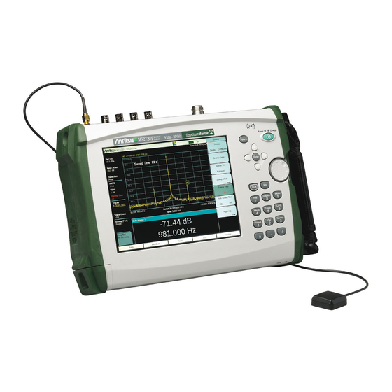
- Page 23 2 Обзор прибора 2-1 Введение В этой главе дается краткий обзор анализатора спектра Anritsu MS2720T Spectrum Master. Целью данной главы является ознакомление пользователя с прибором. Для немедленного начала работы с прибором перейдите к Главе 3 «Начало работы», которая содержит...
-
Page 24: Включение Прибора Ms2720T Первый Раз
2-2 Обзор аппаратных средств Включение прибора MS2720T первый раз Anritsu MS2720T Spectrum Master может непрерывно работать приблизительно 3 часа от полностью заряженной батареи с возможностью ее замены в условиях эксплуатации (раздел «Замена аккумуляторной батареи» на стр. 1-7). MS2720T может также работать от... - Page 25 ООО "Техэнком" Контрольно-измерительные приборы и оборудование www.tehencom.com Обзор прибора 2-3 Обзор разъемов измерительной панели Измерительная панель, показанная на рис. 2-2, относится к опциям с более низкими частотными диапазонами, которые также допускают подключение опции «Следящий генератор». Описание разъемов приводится ниже. Обратите внимание, что опция «Следящий генератор» не установлена, а...
- Page 26 ООО "Техэнком" Контрольно-измерительные приборы и оборудование www.tehencom.com Обзор прибора Измерительная панель, показанная на рис. 2-3, относится к двум опциям с высокими частотными диапазонами. Описание разъемов приводится ниже. Рисунок 2-3. Разъемы измерительной панели опций 732, 743 анализатора MS2720T Ввод внешнего сигнала запуска Ext Trigger In Ввод...
- Page 27 ООО "Техэнком" Контрольно-измерительные приборы и оборудование www.tehencom.com Обзор прибора Порт ввода ВЧ сигнала анализатора спектра (RF In) Порт ввода RF In представляет собой гнездовой разъем типа N 50Ω (MS2720T-0709, MS2720T- 0713, MS2720T-0720). Для затягивания разъема типа N не используйте плоскогубцы или рожковый...
- Page 28 ООО "Техэнком" Контрольно-измерительные приборы и оборудование www.tehencom.com Обзор прибора USB интерфейс – тип Mini-B Чтобы подключить MS2720T Spectrum Master напрямую к ПК можно использовать интерфейс USB 2.0. При первом подключении MS2720T к ПК произойдет определение USB устройства операционной системой компьютера. На компакт-диске, поставляемом с прибором, находится драйвер...
- Page 29 ООО "Техэнком" Контрольно-измерительные приборы и оборудование www.tehencom.com Обзор прибора Уход за разъемами Тщательно осмотрите разъемы на наличие общего износа, наличие загрязнений и повреждений, таких как погнутые выводы и накручивающиеся части разъемов. Поврежденные разъемы необходимо сразу же отремонтировать или заменить. Загрязнение разъемов может отрицательно сказаться...
- Page 30 ООО "Техэнком" Контрольно-измерительные приборы и оборудование www.tehencom.com Обзор прибора Обзор передней панели Выполненный на базе меню интерфейс анализатора Spectrum Master прост в использовании и не требует длительного обучения. Рисунок 2-4. Обзор передней панели Панель разъемов Выходное вентиляционное отверстие Клавиши подменю (активное меню или активный функциональный блок) Кнопка...
- Page 31 ООО "Техэнком" Контрольно-измерительные приборы и оборудование www.tehencom.com Обзор прибора Графический интерфейс пользователя (ГИП) Экран измерения (окно развертки) служит для вывода данных об измерении в виде кривой измерения. Над сеткой и кривой измерения отображаются дополнительные данные об измерении, а в верхнем правом углу индицируется режим, в котором находится анализатор в данный момент. Нижнюю...
- Page 32 ООО "Техэнком" Контрольно-измерительные приборы и оборудование www.tehencom.com Обзор прибора Клавиши на передней панели См. рис. 2-4 на стр. 2-8. Название «аппаратная кнопка» относится к кнопкам на передней панели прибора. Помимо аппаратных кнопок прибор имеет сенсорные клавиши, отображаемые на экране прибора (сенсорные клавиши подменю, сенсорные клавиши главного меню, иконки для навигации по...
- Page 33 ООО "Техэнком" Контрольно-измерительные приборы и оборудование www.tehencom.com Обзор прибора Клавиша ввода десятичной точки Нажатие клавиши позволяет вводить величины с десятичными знаками. Клавиша +/– Данная клавиша предназначена для изменения знака чисел, вводимых с помощью числовой клавиатуры. Для сохранения текущего изображения на экране нажмите три клавиши: Shift, десятичная...
-
Page 34: Клавиша Menu
ООО "Техэнком" Контрольно-измерительные приборы и оборудование www.tehencom.com Обзор прибора Доступные режимы измерения зависят от модели и подключенных опций. Подробнее см. в таблице 1-2 на стр. 1-3. Сенсорные клавиши подменю Сенсорные клавиши подменю располагаются в активном функциональном блоке (метки клавиш подменю) по правому краю экрана. Метки подменю изменяются в зависимости от выбранного режима... - Page 35 ООО "Техэнком" Контрольно-измерительные приборы и оборудование www.tehencom.com Обзор прибора На рис. 2-7 показан экран клавиши Menu, на котором расположены ярлыки установленных режимов измерения и четыре ряда пользовательских ярлыков для быстрого доступа к меню и файлам настройки. Чтобы добавить ярлык на экран, нажмите и удерживайте клавишу в течение нескольких секунд. Например, чтобы...
- Page 36 ООО "Техэнком" Контрольно-измерительные приборы и оборудование www.tehencom.com Обзор прибора Справку по экрану Menu можно вызвать нажатием «вопросительного знака» в нижнем правом углу экрана. Рисунок 2-8. Справка по экрану Menu РЭ MS2720T 2-14 PN: 10580-00340R ред. А...
- Page 37 создании файла измерения с расширением *.spa. Для возврата в нормальный сенсорный режим ввода необходимо перезагрузить прибор (отключить питание, а затем снова его подать). В случае повреждения сенсорного экрана см. раздел 1-2 «Обращение в Anritsu» на стр. 1-1. РЭ MS2720T 2-15...
- Page 38 ООО "Техэнком" Контрольно-измерительные приборы и оборудование www.tehencom.com Обзор прибора Рисунок 2-9. Пример управления с помощью стрелок РЭ MS2720T 2-16 PN: 10580-00340R ред. А...
-
Page 39: Меню Выбора Режима (Mode Selector)
ООО "Техэнком" Контрольно-измерительные приборы и оборудование www.tehencom.com Обзор прибора 2-8 Меню выбора режима (Mode Selector) Для доступа к функциям в меню Mode нажмите сначала клавишу Shift, затем клавишу Mode (9). Для выделения выбранной позиции воспользуйтесь клавишами со стрелками или поворотной кнопкой, затем... - Page 40 ООО "Техэнком" Контрольно-измерительные приборы и оборудование www.tehencom.com Обзор прибора 2-9 Меню дополнительных функций Нажатие клавиши Shift, а затем цифровой клавиши приводит к появлению на экране меню функции, которая обозначена на цифровой клавише (рис. 2-11). Рисунок 2-11. Клавиатура и меню дополнительных функций Не...
- Page 41 На рис. 2-12 показаны некоторые информационные области экрана MS2720Т. Детальное описание режима анализатора спектра приводится в «Руководстве по проведению измерений анализатора спектра» (шифр продукта Anritsu 10580-00349), которое находится диске с документацией и доступно на сайте компании Anritsu. Полный перечень руководств по проведению измерений...
- Page 42 ООО "Техэнком" Контрольно-измерительные приборы и оборудование www.tehencom.com Обзор прибора Рисунок 2-12. Экран в режиме анализатора спектра Часы реального времени (а также широта и долгота при наличии GPS) Сводные данные, значения активных маркеров Экран измерения или сетка измерения или окно развертки Индикатор...
- Page 43 нажав клавишу Esc. Существует возможность редактирования некоторых списков (например, списки антенн или разветвителей) на компьютере и их последующего импорта в Spectrum Master с помощью ПО Master Software Tools или Anritsu Line Sweep Tools (LST). РЭ MS2720T 2-21 PN: 10580-00340R ред. А...
- Page 44 ООО "Техэнком" Контрольно-измерительные приборы и оборудование www.tehencom.com Обзор прибора Ввод текста Для ввода текста (например, при сохранении результатов измерения в файле) на сенсорном экране отображается клавиатура (рис. 2-13). Ввод символов осуществляется непосредственно с клавиатуры на сенсорном экране. Для ввода числовой информации можно использовать приборную...
- Page 45 Рисунок 2-15. Индикатор зарядки батареи Светодиодный индикатор зарядки батареи на передней панели прибора (рис. 2-4 на стр. 2-8) мигает при осуществлении зарядки и горит непрерывно, когда батарея полностью заряжена. Для работы с анализатором используйте только одобренные компанией Anritsu Внимание аккумуляторы, адаптеры и зарядные устройства.
- Page 46 ООО "Техэнком" Контрольно-измерительные приборы и оборудование www.tehencom.com Обзор прибора Иконка сохранения Рисунок 2-17. Иконка сохранения данных (на флоппи-диск) Изображение флоппи-диска 3,5’’ является ярлыком для быстрого доступа к меню Save (стр. 4-10). Иконка располагается между данными GPS и символом батареи в верхней части экрана. Прикосновение...
- Page 47 ООО "Техэнком" Контрольно-измерительные приборы и оборудование www.tehencom.com Обзор прибора 2-14 Обзор клавиш меню Клавиши главного меню Пять клавиш главного меню расположены горизонтально под нижней кромкой экрана. Эти клавиши используются для вызова функционально-специализированных экранных меню (меток подменю). Значения клавиш главного меню меняются в зависимости от текущего режимы работы прибора...
- Page 48 ООО "Техэнком" Контрольно-измерительные приборы и оборудование www.tehencom.com Обзор прибора Таблица 2-1. Значения клавиш главного меню в зависимости от режима работы (2 из 2) Режим Клавиша 1 Клавиша 2 Клавиша 3 Клавиша 4 Клавиша 5 Анализатор Freq Amplitude Setup Measurements сигналов (Частота) (Амплитуда) (Установки)
- Page 49 Начало работы Введение Глава 3 содержит краткий обзор анализатора Anritsu MS2720T Spectrum Master. Цель этой главы – предоставить пользователю начальные знания по настройке параметров, необходимых для проведения базовых измерений. В данной главе описывается подготовка к измерениям, включая выбор режима измерения, настройку частоты, частотного диапазона и амплитуды, полосы обзора, ограничительных...
- Page 50 ООО "Техэнком" Контрольно-измерительные приборы и оборудование www.tehencom.com Начало работы На рисунке 3-1 показан пример спектрограммы на экране. Рисунок 3-1. Пример спектрограммы РЭ MS2720T PN: 10580-00340R ред. А...
- Page 51 ООО "Техэнком" Контрольно-измерительные приборы и оборудование www.tehencom.com Начало работы 3-2 Подготовка к измерениям Подключение источника входного сигнала Подключите источник входного сигнала или антенну к ВЧ-разъему панели тестирования в верхней части прибора. Описание разъемов см. на рис. 2-2 на стр. 2-3. Редактирование...
- Page 52 ООО "Техэнком" Контрольно-измерительные приборы и оборудование www.tehencom.com Начало работы 3-3 Установка частоты измерений Использование начальной и конечной частоты 1. Нажмите клавишу главного меню Freq (частота). 2. Нажмите клавишу подменю Start Freq (начальная частота). 3. Введите значение начальной частоты с помощью клавиатуры. Нажмите клавишу подменю, соответствующую...
- Page 53 ООО "Техэнком" Контрольно-измерительные приборы и оборудование www.tehencom.com Начало работы 3-4 Установка амплитуды Нажмите клавишу главного меню Amplitude (амплитуда) для отображения меню Amplitude (амплитуда). Установка опорного уровня и шкалы Режимы анализатора спектра и анализа интерференций Для изменения текущих единиц измерения нажмите клавишу подменю Units (единицы измерения) и...
- Page 54 ООО "Техэнком" Контрольно-измерительные приборы и оборудование www.tehencom.com Начало работы Установка смещения уровня для компенсации внешнего ослабления или внешнего усиления Для получения точных результатов измерения рекомендуется выполнить компенсацию внешнего ослабления или усиления с помощью подменю RL Offset. Коэффициент компенсации установлен в дБ. Внешнее ослабление может быть результатом использования внешнего кабеля или внешнего...
- Page 55 ООО "Техэнком" Контрольно-измерительные приборы и оборудование www.tehencom.com Начало работы 3-6 Установка ограничительных линий Нажмите клавишу Shift, а затем клавишу цифровой клавиатуры Limit (6) для отображения меню Limit (ограничение). Простая ограничительная линия Режимы анализатора спектра и анализатора интерференций Нажмите клавишу Shift, а затем клавишу Limit (6). ...
- Page 56 ООО "Техэнком" Контрольно-измерительные приборы и оборудование www.tehencom.com Начало работы Сегментированная ограничительная линия Режимы анализатора спектра и анализатора интерференций На рисунке 3-2 показан пример сегментированной ограничительной линии. После того, как была построена правая половина ограничительной линии, ее левая часть была достроена автоматически посредством...
- Page 57 ООО "Техэнком" Контрольно-измерительные приборы и оборудование www.tehencom.com Начало работы 3-7 Установка маркеров Нажмите клавишу главного меню Marker. На экране появится окно Select Marker (см. рис. 3-4). Для активизации маркера прикоснитесь к выбранному маркеру. После активизации маркер можно перемещать с помощью других клавиш подменю. Подробнее см. в руководстве по измерению с помощью...
- Page 58 ООО "Техэнком" Контрольно-измерительные приборы и оборудование www.tehencom.com Начало работы Просмотр значений маркера в табличном формате Нажмите клавишу подменю More (далее). Нажмите клавишу подменю Marker Table On/Off (таблица маркеров «Вкл/Выкл») так, чтобы позиция On была выделена подчеркиванием. Все данные по маркерам и дельта-маркерам отображаются...
- Page 59 Подробнее см. в главе 4 «Управление файлами» 3-10 Master Software Tools Программное обеспечение Anritsu Master Software Tools – это набор программ для работы в операционной системе Windows, предназначенный для передачи сохраненных измерений, маркеров и ограничительных линий на ПК. Подробнее о ПО Master Software Tools см. в главе 7.
- Page 60 ООО "Техэнком" Контрольно-измерительные приборы и оборудование www.tehencom.com Начало работы РЭ MS2720T 3-12 PN: 10580-00340R ред. А...
- Page 61 ООО "Техэнком" Контрольно-измерительные приборы и оборудование www.tehencom.com Управление файлами 4-1 Введение В этой главе описываются функции анализатора Spectrum Master по управлению файлами, а также дается описание соответствующих меню. Клавиши подменю в меню File позволяют сохранять, загружать, копировать и удалять файлы в памяти прибора и на внешнем USB диске. 4-2 Управление...
- Page 62 ООО "Техэнком" Контрольно-измерительные приборы и оборудование www.tehencom.com Управление файлами Сохранение файлов Выбор клавиши подменю для выполнения операции с файлами зависит от модели прибора и режимов анализатора. Выбор устройства хранения Нажмите клавишу подменю Save (сохранить), затем клавишу подменю Change Save Location (изменить...
- Page 63 ООО "Техэнком" Контрольно-измерительные приборы и оборудование www.tehencom.com Управление файлами Сохранить экран измерений как JPEG рисунок Нажмите клавишу подменю Save (сохранить), введите имя JPEG-файла, убедитесь, что тип файла установлен на JPEG и нажмите клавишу Enter для сохранения. Диалоговое окно Save Диалоговое окно Save (рис. 4-1) используется для сохранения файлов во внутренней памяти или на внешнем...
- Page 64 ООО "Техэнком" Контрольно-измерительные приборы и оборудование www.tehencom.com Управление файлами Вызов файлов Меню Recall позволяет просматривать все файлы с измерениями и настройками, сохраненные во внутренней памяти или на внешнем USB флеш-накопителе. Содержимое меню Recall можно отсортировать по имени, дате или типу. Также можно отобразить только...
- Page 65 ООО "Техэнком" Контрольно-измерительные приборы и оборудование www.tehencom.com Управление файлами Диалоговое окно Recall Диалоговое окно Recall (рис. 4-2) позволяет открыть ранее сохраненные измерения и настройки. Подробнее см. раздел «Меню Recall» на стр. 4-13. Рисунок 4-2. Диалоговое окно Recall Копирование файлов Ниже подробно описывается процедура копирования файла из внутренней памяти на внешний флеш- накопитель.
- Page 66 ООО "Техэнком" Контрольно-измерительные приборы и оборудование www.tehencom.com Управление файлами Нажмите клавишу Copy для копирования файлов на флеш-накопитель. Рисунок 4-3. Диалоговое окно Copy Чтобы свернуть/развернуть папки, используйте клавиши со стрелками Примечание влево/вправо. РЭ MS2720T PN: 10580-00340R ред. А...
-
Page 67: Диалоговое Окно Delete
ООО "Техэнком" Контрольно-измерительные приборы и оборудование www.tehencom.com Управление файлами Удаление файлов Удаление выбранного файла или файлов Нажмите клавишу подменю Delete. Выделите файл, который нужно удалить, с помощью сенсорного экрана или клавиш со стрелками вверх/вниз. Нажмите клавишу Select or De-Select. Выделенный файл будет... -
Page 68: Обзор Меню File
ООО "Техэнком" Контрольно-измерительные приборы и оборудование www.tehencom.com Управление файлами Обзор меню File Данное меню открывается нажатием клавиши Shift, затем клавиши File (7). Карты меню, как правило, отображают все возможные клавиши подменю, несмотря на то, что некоторые клавиши присутствуют на экране прибора только при определенных обстоятельствах (см. описание меню на следующих страницах). -
Page 69: Меню Save
ООО "Техэнком" Контрольно-измерительные приборы и оборудование www.tehencom.com Управление файлами Меню File Последовательность нажатия клавиш:Shift > File Save Measurement As: Данная клавиша позволяет сохранить текущую настройку под именем, определенным пользователем. Имя файла, устанавливаемое по умолчанию, изменяется с помощью подменю Save. Чтобы изменить... -
Page 70: Меню File Type
ООО "Техэнком" Контрольно-измерительные приборы и оборудование www.tehencom.com Управление файлами Меню Save Последовательность нажатия клавиш:Shift > File > Save (7) Change Quick Name: Нажатие данной клавиши подменю позволяет изменить метки клавиш быстрых имен в нижней части сенсорной клавиатуры (рис. 4-1 на стр. 4-3). - Page 71 ООО "Техэнком" Контрольно-измерительные приборы и оборудование www.tehencom.com Управление файлами Меню Save Location Последовательность нажатия клавиш: Shift > File (7) > Save > Change Save Location Данное меню используется для создания папок и выбора места для сохранения прибором Spectrum Master текущего файла. Файлы или диски можно выбрать с помощью...
-
Page 72: Меню Save On
ООО "Техэнком" Контрольно-измерительные приборы и оборудование www.tehencom.com Управление файлами Меню Save On… Последовательность нажатия клавиш: Shift > File (7) > Save On Event Меню доступно не во всех режимах. Меню используется для автоматического сохранения измерений во внутреннюю память после появления одного из следующих... -
Page 73: Меню Recall
ООО "Техэнком" Контрольно-измерительные приборы и оборудование www.tehencom.com Управление файлами Меню Recall Данное меню и диалоговое окно (рис. 4-13 на стр. 4-14) используется для просмотра папок и выбора файлов для загрузки в Spectrum Master. Файлы или папки можно выбрать с помощью клавиш со стрелками... - Page 74 ООО "Техэнком" Контрольно-измерительные приборы и оборудование www.tehencom.com Управление файлами Диалоговое окно Recall Выберите папки или файлы с помощью клавиш со стрелками вверх/вниз, поворотной кнопки или сенсорного экрана. Рисунок 4-13. Диалоговое окно Recall РЭ MS2720T 4-14 PN: 10580-00340R ред. А...
-
Page 75: Меню Copy
ООО "Техэнком" Контрольно-измерительные приборы и оборудование www.tehencom.com Управление файлами Меню Copy Данное меню и диалоговое окно используются для копирования файлов и папок. Папки или файлы можно выбрать с помощью клавиш со стрелками вверх/вниз или поворотной кнопки. На рис. 4-15 на стр. 4-16 показано... - Page 76 ООО "Техэнком" Контрольно-измерительные приборы и оборудование www.tehencom.com Управление файлами Диалоговое окно Copy Рисунок 4-15. Диалоговое окно Copy РЭ MS2720T 4-16 PN: 10580-00340R ред. А...
-
Page 77: Диалоговое Окно Delete
ООО "Техэнком" Контрольно-измерительные приборы и оборудование www.tehencom.com Управление файлами Меню Delete Последовательность нажатия клавиш: Shift > File (7) > Delete Данное меню и диалоговое окно используется для удаления папок и файлов. Папки или файлы можно выбрать с помощью клавиш со стрелками вверх/вниз или... - Page 78 ООО "Техэнком" Контрольно-измерительные приборы и оборудование www.tehencom.com Управление файлами Диалоговое окно Delete Рисунок 4-17. Диалоговое окно Delete РЭ MS2720T 4-18 PN: 10580-00340R ред. А...
- Page 79 ООО "Техэнком" Контрольно-измерительные приборы и оборудование www.tehencom.com 5 Системные операции 5-1 Введение В этой главе описываются системные операции Spectrum Master. Описание других меню (Sweep (развертка), Measure (измерение), Trace (кривая измерения), Limit (ограничение)) приводится в руководствах по проведению измерений (Приложение А). РЭ...
-
Page 80: Обзор Меню System
ООО "Техэнком" Контрольно-измерительные приборы и оборудование www.tehencom.com Системные операции 5-2 Обзор меню System Для доступа к меню System (система) нажмите клавишу Shift, затем клавишу System (8). На рис. 5-1 и 5-2 показана группа меню, которая доступна из меню System. Карты меню, как правило, отображают все возможные... -
Page 81: Меню System – Карта 2
ООО "Техэнком" Контрольно-измерительные приборы и оборудование www.tehencom.com Системные операции Меню System – карта 2 Рисунок 5-2. Меню System – часть 2 РЭ MS2720T PN: 10580-00340R ред. А... -
Page 82: Меню System
(прошел) или Fail (не прошел). Если процедура тестирования завершилась неудачно, то необходимо обратиться в ближайший центр обслуживания Anritsu (см. раздел «Обращение в Anritsu» на стр. 1-1) и сообщить результаты тестирования. Некоторые из узлов анализатора, тестирование которых выполняется в рамках данной процедуры, также могут использоваться в нескольких режимах работы. -
Page 83: Меню System Options
ООО "Техэнком" Контрольно-измерительные приборы и оборудование www.tehencom.com Системные операции Меню System Options Последовательность нажатия клавиш: Shift> System (8) > System Options Date & Time: Нажатие данной клавиши вызывает диалоговое окно для настройки текущей даты и времени. С помощью клавиш подменю или клавиш со стрелками влево/вправо... -
Page 84: Меню System Options 2/2
ООО "Техэнком" Контрольно-измерительные приборы и оборудование www.tehencom.com Системные операции Меню System Options 2/2 Последовательность нажатия клавиш: Shift> System (8) > System Options > More Share CF & Pwr Offset All Modes Not Shared: Нажатие клавиши позволяет переключаться между режимом All Modes (все режимы) и Not Shared (не распространяется на все). В режиме... - Page 85 ООО "Техэнком" Контрольно-измерительные приборы и оборудование www.tehencom.com Системные операции Пароль для доступа в дистанционном режиме Предупреждение Не используйте команды SPCI с данной функцией Данная функция используется только с Master Software Tools (MST) версии 2.21.1 и выше. После настройки пароля прибор необходимо перезагрузить (отключение питания (OFF), затем включение (ON)), чтобы...
-
Page 86: Меню Power-On
ООО "Техэнком" Контрольно-измерительные приборы и оборудование www.tehencom.com Системные операции Меню Power-On Последовательность нажатия клавиш: Shift> System (8) > System Options > More > Power-On Power Switch: Нажатие данной клавиши подменю позволяет установить нормальный режим использования кнопки On/Off на передней панели. When DC Applied: Нажатие... -
Page 87: Меню Display Settings
ООО "Техэнком" Контрольно-измерительные приборы и оборудование www.tehencom.com Системные операции Меню Display Settings Последовательность нажатия клавиш: Shift, System (8) > System Options > Display Brightness: Пользователь имеет возможность регулировать яркость экрана, что позволяет оптимизировать видимость в различных условиях освещенности. Уровень яркости можно изменить с помощью клавиш со стрелками вверх/вниз (с шагом... -
Page 88: Меню Reset
Примечание: Та же процедура сброса может быть запущена при включении Spectrum Master посредством нажатия и удерживания клавиш System (8)+On до появления экрана-заставки Anritsu. Update Firmware: Нажатие данной клавиши позволяет выполнить обновление операционной системы прибора с помощью карты памяти USB. Нажмите... -
Page 89: Меню Preset
Если Spectrum Master находится в пределах указанного рабочего диапазона и аккумулятор заряжен, а процедура самотестирования завершается неудачно, следует обратить в ближайший сервисный центр Anritsu. Если анализатор уже включен, то процедуру самотестирования можно запустить следующим образом: 1. Нажмите клавишу Shift, затем клавишу System (8). -
Page 90: Обновление Встроенного По Анализатора Spectrum Master
5-6 Обновление встроенного ПО анализатора Spectrum Master Для выполнения обновления встроенного программного обеспечения в анализаторе Spectrum Master необходимо загрузить файл обновления с сайта Anritsu, записать его на карту памяти USB и загрузить обновление в Spectrum Master. Способы выполнения обновления описаны на сайте Anritsu: http://www.anritsu.com/en-US/Products-Solutions/Instructional/Handheld-Firmware-Methods.aspx... -
Page 91: Обновление Программного Обеспечения Через Usb
Контрольно-измерительные приборы и оборудование www.tehencom.com Системные операции На странице Firmware Update for the Spectrum Master MS2720T щелкните по кнопке Download и сохраните файл на ваш ПК, следуя инструкциям на экране. После завершения загрузки запустите файл. На экране появится мастер обновления, который будет... - Page 92 ООО "Техэнком" Контрольно-измерительные приборы и оборудование www.tehencom.com Системные операции РЭ MS2720T 5-14 PN: 10580-00340R ред. А...
- Page 93 6 GPS (Опция 31) 6-1 Введение Анализатор Spectrum Master MS2720T может поставляться со встроенным GPS-приемником (Опция 31), обеспечивающим получение информации о широте, долготе, высоте и универсальном глобальном времени. При активном отслеживании спутников данные GPS сохраняются при каждом сохранении результатов измерения и могут быть отображены с помощью Master Software Tools. Эта опция также...
- Page 94 ООО "Техэнком" Контрольно-измерительные приборы и оборудование www.tehencom.com GPS (Опция 31) 5. Нажмите клавишу подменю GPS Info для просмотра следующей информации: o Отслеживаемые спутники o Широта и долгота o Высота o Универсальное глобальное время o Установленное местоположение o Альманах готов o Состояние антенны o Состояние...
- Page 95 ООО "Техэнком" Контрольно-измерительные приборы и оборудование www.tehencom.com GPS (Опция 31) 6-3 Меню GPS Последовательность нажатия клавиш: Shift, System (8) > GPS GPS: Нажатие данной клавиши подменю позволяет включить (on) или выключить (off) GPS. GPS Info: Нажатие данной клавиши подменю отображает текущую информацию GPS.
- Page 96 Short/Open: Между антенной и точкой подключения имеется короткое замыкание или разрыв. В случае появления этого сообщения необходимо отключить и переместить антенну GPS. Если сообщение не исчезает, попробуйте подключить другую антенну GPS производства Anritsu (подробнее см. на стр. 1-4 «Стандартные и дополнительные принадлежности»). Если замена...
- Page 97 Обновление встроенного программного обеспечения. 7-2 Обзор Master Software Tools Программа Master Software Tools компании Anritsu – это совместимая с операционной системой Microsoft® Windows® (Windows 2000 и выше) программа, предназначенная для передачи результатов измерений, включая маркеры и ограничительные линии, на ПК с целью их последующего...
- Page 98 5. Внесение изменений в список кабелей, антенн и стандартов сигналов. 6. Математические функции с кривыми. 7. Конвертирование файлов DAT из формата Anritsu Handheld Software Tools в формат Anritsu Master Software Tools. Рисунок 7-1. Master Software Tools с несколькими открытыми измерениями...
- Page 99 ООО "Техэнком" Контрольно-измерительные приборы и оборудование www.tehencom.com Master Software Tools Редактирование кривых С помощью MST можно изменять масштаб, редактировать ограничительные линии и маркеры на кривой. Для этого используется клавиша Edit Graph (отредактировать график) и контекстные меню. 1. Добавление, удаление и изменение ограничительных линий и маркеров 2.
- Page 100 ООО "Техэнком" Контрольно-измерительные приборы и оборудование www.tehencom.com Master Software Tools Трехмерная спектрограмма Трехмерная спектрограмма (Folder Spectrogram) позволяет создавать трехмерное отображение больших массивов данных в одном наборе графиков. 1. Возможность отображения кривых в виде каскадной диаграммы, 3D или ролика в формате .avi. 2.
- Page 101 Ethernet. Возможность обновления программного обеспечения прибора до самых последних версий, доступных на: http://www.anritsu.com Рисунок 7-4. Использование инструмента дистанционного подключения к прибору в сети Контекстные меню Контекстные меню служат в качестве ярлыков к командам, которые также доступны на выпадающих меню и панели инструментов.
- Page 102 Программа Master Software Tools находится на CD диске, который входит в комплект поставки прибора. Для установки программы на ПК вставьте CD диск в дисковод и следуйте указаниям программы установки. Программу MST также можно скачать на сайте http://www.anritsu.com. 7-5 Подключение к прибору...
-
Page 103: Приложение A - Сопутствующая Документация
В этом приложении приводится перечень вспомогательной документации по конструктивным особенностям и опциям Spectrum Master. Руководства по проведению измерений в формате PDF находятся на диске с документацией или могут быть загружены с сайта компании Anritsu. Для определения версии встроенного программного обеспечения вашего прибора см. описание клавиши... -
Page 104: Сопутствующая Документация
2300-532 Документация по работе с переносными приборами (компакт-диск) 10920-00060 Дополнительные документы находятся под вкладкой Library на странице каждого из изделий Anritsu. Актуальная информация по изделиям доступна на сайте Anritsu: http://www.anritsu.com Выполните поиск по номеру модели. Актуальная документация находится на странице изделия под... -
Page 105: Приложение B - Работа В Защищенной Среде
ООО "Техэнком" Контрольно-измерительные приборы и оборудование www.tehencom.com Приложение B - Работа в защищенной среде Введение В данном разделе описываются Опция 7 (Безопасная работа с данными) и функция «Скрытие частоты», типы используемой в Spectrum Master памяти, процедура удаления пользовательских файлов, сохраненных во внутренней памяти, а также рекомендации по работе в условиях, когда требуется защита информации. -
Page 106: Пароль При Работе В Дистанционном Режиме
ООО "Техэнком" Контрольно-измерительные приборы и оборудование www.tehencom.com Работа в защищенной среде Пароль при работе в дистанционном режиме Данная функция используется только с Master Software Tools (MST) версии 2.21.1 и выше. Пароль сначала устанавливается в прибор, а затем используется в MST. Целью пароля является защита Spectrum Master от... -
Page 107: Удаление Всех Файлов Пользователя Из Внутренней Памяти
ООО "Техэнком" Контрольно-измерительные приборы и оборудование www.tehencom.com Работа в защищенной среде Удаление всех файлов пользователя из внутренней памяти Процедура главного сброса: 1. Включите прибор. 2. Нажмите кнопку Shift, затем кнопку System (8). 3. Нажмите клавишу подменю System Options. 4. Нажмите клавишу Reset, затем клавишу Master Reset. 5. -
Page 108: Рекомендуемое Использование В Защищенной Среде
Рекомендуемое использование в защищенной среде В настоящее время Spectrum Master не имеет функции безопасного удаления данных. В ситуациях, когда защита данных имеет значение, компания Anritsu рекомендует хранитьфайлы, созданные Spectrum Master, на внешнем USB флеш-накопителе, который затем будет храниться в соответствующих условиях, а... -
Page 109: Приложение C - Сообщения Об Ошибках
Приложение C - Сообщения об ошибках Введение В этой главе приводится список информационных сообщений и сообщений об ошибках, которые могут отобразиться на экране Spectrum Master MS2720T. Если состояние ошибки сохраняется, свяжитесь с местным сервисным центром компании Anritsu (http://www.anritsu.com/Contact.asp). Ошибки самодиагностики системы и самодиагностики... - Page 110 RESET (System+ON). ПРЕДУПРЕЖДЕНИЕ: MASTER RESET (System+ON) удаляет все сохраненные пользовательские настройки и кривые измерения и устанавливает все заводские параметры по умолчанию. Если состояние ошибки сохраняется, свяжитесь с местным центром Anritsu. Trace not saved. Please wait for complete sweep and try again (Кривая не сохранена.
- Page 111 заводских параметров: Factory Defaults (ESC+ON) или MASTER RESET (System+ON). ПРЕДУПРЕЖДЕНИЕ: MASTER RESET (System+ON) удаляет все сохраненные пользовательские настройки и кривые измерения и устанавливает заводские параметры. Если состояние ошибки сохраняется, свяжитесь с местным центром Anritsu. РЭ MS2720T PN: 10580-00340R ред. А...
- Page 112 ПРЕДУПРЕЖДЕНИЕ: MASTER RESET (System+ON) удаляет все сохраненные пользовательские настройки и кривые измерения и устанавливает заводские параметры. Если состояние ошибки сохраняется, свяжитесь с местным центром Anritsu. Cannot set Delta Mkr Freq to Demod Freq (невозможно установить частоту дельта-маркера на частоту демодуляции) Установка...
- Page 113 восстановлением заводских параметров: Factory Defaults (ESC+ON) или MASTER RESET (System+ON). ПРЕДУПРЕЖДЕНИЕ: MASTER RESET (System+ON) удаляет все сохраненные пользовательские настройки и кривые измерения и устанавливает заводские параметры. Если состояние ошибки сохраняется, свяжитесь с местным центром Anritsu. Copy Failed. Please check External USB Memory (ошибка копирования. Проверьте внешний USB диск) Сбой...
- Page 114 ООО "Техэнком" Контрольно-измерительные приборы и оборудование www.tehencom.com Сообщения об ошибках РЭ MS2720T PN: 10580-00340R ред. А...
-
Page 115: Подключение К Лвс
Приложение D - Подключение к ЛВС и протокол DHCP Введение В этом приложении описываются особенности подключения Spectrum Master MS2720T к ЛВС. Конфигурация Ethernet Подключение к ЛВС Для подключения прибора к ЛВС используется разъем RJ48С. В этот разъем встроены два индикатора: желтый... - Page 116 ООО "Техэнком" Контрольно-измерительные приборы и оборудование www.tehencom.com Подключение к ЛВС и протокол DHCP Для того чтобы узнать IP адрес прибора, нажмите клавишу Shift, затем клавишу System (8). Потом нажмите контекстные клавиши System Options и Ethernet Config. IP адрес отобразится так, как показано...
-
Page 117: Конфигурация Ethernet
ООО "Техэнком" Контрольно-измерительные приборы и оборудование www.tehencom.com Подключение к ЛВС и протокол DHCP Конфигурация Ethernet Нажмите клавишу Ethernet Config для отображения меню Ethernet и открытия диалогового окна Ethernet Editor для ввода IP адреса вручную (рис. D-2). Рисунок D-2. Настройка IP-адреса вручную РЭ... -
Page 118: Меню Ethernet
ООО "Техэнком" Контрольно-измерительные приборы и оборудование www.tehencom.com Подключение к ЛВС и протокол DHCP Меню Ethernet Последовательность нажатия клавиш: Shift, System (8) -> System Options-> Ethernet Config Type (тип) Manual (вручную) / DHCP: Нажмите данную клавишу для выбора типа адресации: статическая (адрес... -
Page 119: D-3 Dhcp
ООО "Техэнком" Контрольно-измерительные приборы и оборудование www.tehencom.com Подключение к ЛВС и протокол DHCP DHCP DHCP - это протокол динамической конфигурации узла. Это протокол, позволяющий серверу автоматически назначать IP адреса устройствам, подключенным к сети. Большинство сетей используют DHCP сервер для администрирования IP адресов. Если в сети имеется DHCP сервер, то распределение адресов... - Page 120 Windows 2000 IP Configuration Ethernet adapter Local Area Connection: Connection-specific DNS Suffix. : us.anritsu.com IP Address....: 172.26.202.172 Subnet Mask ... . . : 255.255.252.0 Default Gateway .
- Page 121 ООО "Техэнком" Контрольно-измерительные приборы и оборудование www.tehencom.com Подключение к ЛВС и протокол DHCP Команда ping Другим инструментом, который может выяснить, есть ли в сети выбранный IP адрес, является команда ping. Команда ping - это безопасный способ определить, есть ли в сети заданный адрес, и если адрес найден, получить...
- Page 122 Опция 27 Выход ПЧ в нулевой полосе обзора Опция 89 Ждущая развертка Опция 90 Генератор непрерывных сигналов Опция 28 Шифр компонента: 10580-00231 Anritsu Company Редакция: В 490 Jarvis Drive Опубликовано: август 2009 Morgan Hill, CA 95037-2809 Copyright 2009 Anritsu Company...
- Page 123 ПРИЗНАНИЕ ТОРГОВЫХ МАРОК Windows и Windows XP являются зарегистрированными торговыми марками Microsoft Corporation. BTS Master, Site Master, Cell Master и Spectrum Master являются торговыми марками компании Anritsu. ВНИМАНИЕ Компания Anritsu разработала данное руководство по эксплуатации для использования сотрудниками компании...
- Page 124 Контрольно-измерительные приборы и оборудование www.tehencom.com Знаки безопасности В целях предотвращения возможных травм или повреждения оборудования компания Anritsu использует приведенные ниже символы для обозначения информации, которая важна для обеспечения безопасной работы. Для вашей собственной безопасности следует внимательно ознакомиться с данной информацией до начала работы с оборудованием.
- Page 125 ООО "Техэнком" Контрольно-измерительные приборы и оборудование www.tehencom.com Меры безопасности Предупреждение ВСЕГДА обращайтесь к руководству по эксплуатации при работе рядом с местами, на которые распространяется действие знака, показанного слева. Если работа выполняется без соблюдения рекомендаций, содержащихся в руководстве по эксплуатации, существует риск получения травмы. Кроме того, качество...
- Page 126 ООО "Техэнком" Контрольно-измерительные приборы и оборудование www.tehencom.com Содержание Глава 1 - Общая информация..............2-1 1-1 Введение ........................2-1 1-2 Выбор режима измерения ..................2-1 Глава 2 – Анализатор спектра ..............2-1 2-1 Введение ........................2-1 2-2 Общие настройки измерения ..................2-1 2-3 Измерения в режиме анализатора спектра .............2-2 2-4 Полоса...
- Page 127 ООО "Техэнком" Контрольно-измерительные приборы и оборудование www.tehencom.com 2-24 Меню Marker (Маркеры)..................2-32 Меню More Peak Options ....................2-33 Меню Marker 2/2......................2-34 2-25 Меню Sweep (Развертка)..................2-35 Меню Trigger (Запуск)....................2-36 Меню Gated Sweep (Ждущая развертка) (Опция 90) ..........2-37 2-26 Меню Measure (Измерение) ..................2-38 Меню Field Strength (Напряженность поля) ..............2-39 Меню...
- Page 128 ООО "Техэнком" Контрольно-измерительные приборы и оборудование www.tehencom.com 3-11 Меню BW (Полоса пропускания)................3-19 3-12 Меню Measurements (Измерения).................3-20 Меню Spectrum (Спектр) ....................3-21 Меню Field Strength (Напряженность поля) ..............3-22 Меню OCC BW (Занимаемый диапазон частот)............3-22 Меню Channel Power (Мощность в канале) ..............3-23 Меню ACPR (Мощность в соседнем канале)............3-24 Меню...
- Page 129 ООО "Техэнком" Контрольно-измерительные приборы и оборудование www.tehencom.com 4-6 Настройка измерения с помощью Script Master............4-4 4-7 Меню режима сканера каналов (CHS)..............4-6 4-8 Меню Scanner (Сканер) .....................4-7 Меню Channel Scan (Сканируемые каналы)...............4-7 Меню Freq Scan (Частота сканирования) ..............4-8 Меню Scan Script Master....................4-9 4-9 Меню...
- Page 130 ООО "Техэнком" Контрольно-измерительные приборы и оборудование www.tehencom.com Глава 1 - Общая информация 1-1 Введение В данном руководстве по измерению рассматриваются функции анализатора спектров, анализатора интерференции и сканера каналов для следующих приборов компании Anritsu: • BTS Master • Site Master •...
- Page 131 ООО "Техэнком" Контрольно-измерительные приборы и оборудование www.tehencom.com Шифр: 10580-00231 Ред. В Анализатор спектра: РИ...
- Page 132 ООО "Техэнком" Контрольно-измерительные приборы и оборудование www.tehencom.com Глава 2 – Анализатор спектра 2-1 Введение Измерения в режиме анализатора спектра включают в себя использование дополнительных функций помимо функций частоты, полосы обзора, амплитуды и маркеров. В разделе и объясняются процедуры установки и настройки для проведения измерений в режиме анализатора спектра. В разделах с...
- Page 133 ООО "Техэнком" Контрольно-измерительные приборы и оборудование www.tehencom.com Анализатор спектра 2-3 Измерения в режиме анализатора спектра Необходимое оборудование • Опционально, антенна, подходящая для измеряемого частотного диапазона Подготовка • Подайте входной сигнал или подключите антенну к тестовому порту RF In. Установка параметров ширины полосы пропускания Как...
- Page 134 ООО "Техэнком" Контрольно-измерительные приборы и оборудование www.tehencom.com Анализатор спектра Установка параметров развертки Для установки параметров развертки нажмите клавишу Shift, а затем клавишу Sweep (3). Однократная/непрерывная (Single/Continuous) Нажатие клавиши подменю Single/Continuous позволяет переключать прибор между режимами однократной и непрерывной развертки. В режиме однократной развертки прибор после выполнения развертки...
- Page 135 ООО "Техэнком" Контрольно-измерительные приборы и оборудование www.tehencom.com Анализатор спектра амплитуды с клавиатуры или с помощью клавиш со стрелками Влево/Вправо для изменения значения на 1 дБ или клавиш со стрелками Вверх/Вниз для изменения настройки на 10 дБ. Изменение положения триггера (Change Trigger Position): Данная клавиша подменю используется...
- Page 136 ООО "Техэнком" Контрольно-измерительные приборы и оборудование www.tehencom.com Анализатор спектра 2-4 Полоса пропускания Полоса пропускания (RBW) определяет избирательность по частоте. Анализатор спектра отображает форму полосового фильтра, настроенного на сигнал. Выбор полосы пропускания зависит от нескольких факторов. Для выхода в рабочий режим фильтрам требуется время. Требуется некоторое время для установки...
- Page 137 этом случае экран анализатора выглядит смазанным, спектральные линии толще, чем обычно, смещены вправо и с более низкой амплитудой, чем требуется. К счастью, оборудование Anritsu разработано таким образом, чтобы избавить пользователя от необходимости вычислять или экспериментально определять скорость развертки, при которой прибор...
- Page 138 ООО "Техэнком" Контрольно-измерительные приборы и оборудование www.tehencom.com Анализатор спектра Рис. 2-2. Предусилитель выключен Рис. 2-3. Предусилитель включен Анализатор спектра: РИ Шифр: 10580-00231 Ред. В...
- Page 139 ООО "Техэнком" Контрольно-измерительные приборы и оборудование www.tehencom.com Анализатор спектра 2-9 Измерения в полевых условиях В режиме анализатора спектра пользователь имеет возможность с помощью нажатия одной кнопки выполнить измерение напряженности поля, занимаемого диапазона частот, мощности в канале, мощности в соседнем канале и отношение мощности сигнала на несущей к помехе (C/I). Кроме этого в качестве...
- Page 140 ООО "Техэнком" Контрольно-измерительные приборы и оборудование www.tehencom.com Анализатор спектра Вычисление показателей антенны В случае необходимости преобразования одного параметра в другой пользователь может выполнить ряд вычислений: Преобразование значений уровня сигнала из Ватт в вольт в 50-омной системе: P = V где: P = мощность...
- Page 141 • Кабель-удлинитель для тестового порта, шифр Anritsu 15NNF50-1.5С • Аттенюатор 30 дБ, 50 Ватт, двунаправленный, DC – 18 ГГц, N(m) – N(f), шифр Anritsu 42N50A- 30 (требуется, если измеряемый уровень мощности > +30 дБм) Процедура 1. С помощью кабеля-удлинителя для тестового порта и, в случае необходимости, двунаправленного...
- Page 142 ООО "Техэнком" Контрольно-измерительные приборы и оборудование www.tehencom.com Анализатор спектра На Рис. 2-4 показаны результаты измерения занимаемого диапазона частот с использованием метода «% от мощности» на сигнале CDMA. Измерение занимаемого диапазона частот выполняется непрерывно: после включения процедура выполняется постоянно до нажатия клавиши подменю On/Off.
- Page 143 поддержки восьми отдельных разговоров (TDMA). GSM используется модуляцию с помощью гауссовой манипуляции с минимальным сдвигом (GSMK). Необходимое оборудование • Кабель-удлинитель для тестового порта, шифр Anritsu 15ТТА50-1.5С Процедура 1. С помощью кабеля-удлинителя для тестового порта выполните подключение порта RF In к источнику сигнала.
- Page 144 2-13 Измерение мощности в соседнем канале Необходимое оборудование • Аттенюатор 30 дБ, 50 Ватт, двунаправленный, DC – 18 ГГц, N(m) – N(f), шифр Anritsu 42N50A- 30 (требуется, если измеряемый уровень мощности > +30 дБм) • Кабель-удлинитель для тестового порта, шифр Anritsu 15NNF50-1.5С...
- Page 145 Анализатор спектра 2-14 Измерение внеполосного паразитного излучения Необходимое оборудование • Кабель-удлинитель для тестового порта, шифр Anritsu 15NNF50-1.5С Процедура 1. С помощью кабеля-удлинителя для тестового порта подключите источник сигнала к тестовому порту RF In. 2. Нажмите клавишу главного меню Freq, нажмите клавишу подменю Center Freq и введите...
- Page 146 ООО "Техэнком" Контрольно-измерительные приборы и оборудование www.tehencom.com Анализатор спектра 10. Выполните п. 8 и 9 для остальных выступов. Воспользуйтесь снова Маркером 1 или другим маркером. На рисунке 2-5 с помощью дельта-маркера показан моделированный внеполосный паразитный сигнал 3 МГц от несущей. Рис.
- Page 147 Аттенюатор 30 дБ, 50 Ватт, двунаправленный, DC – 18 ГГц, N(m) – N(f), шифр Anritsu 42N50A-30 • Кабель-удлинитель для тестового порта, шифр Anritsu 15NNF50-1.5С Процедура 1. С помощью кабеля-удлинителя для тестового порта и двунаправленного аттенюатора на 30 дБ, 50 Ватт, выполните подключение порта RF In к соответствующему тестовому порту передатчика.
- Page 148 ООО "Техэнком" Контрольно-измерительные приборы и оборудование www.tehencom.com Анализатор спектра 2-17 АМ/ЧМ/однополосная модуляция Встроенный демодулятор для АМ, узкополосной ЧМ, широкополосной ЧМ и одной боковой полосы (верней или нижней) позволяет услышать сигнал помехи. Демодулированный сигнал можно услышать с помощью встроенного динамика или монауральных наушников, подключенных к гнезду 2,5 мм на панели...
- Page 149 ООО "Техэнком" Контрольно-измерительные приборы и оборудование www.tehencom.com Анализатор спектра 2-18 Измерение отношения мощности сигнала на несущей к помехе (C/I) Измерение отношения мощности сигнала на несущей к помехе состоит из двух этапов: сначала измеряется уровень несущей, а затем несущая выключается и измеряются оставшиеся сигналы и шум в интересующей...
- Page 150 ООО "Техэнком" Контрольно-измерительные приборы и оборудование www.tehencom.com Анализатор спектра На рисунках ниже показаны этапы измерения отношения мощности сигнала на несущей к помехе: готовность к измерению несущей 2-6), несущая измерена 2-7), результаты измерения (Рис. (Рис. (Рис. 2-8). Рис. 2-6. Готовность к измерению несущей Рис.
- Page 151 ООО "Техэнком" Контрольно-измерительные приборы и оборудование www.tehencom.com Анализатор спектра Рис. 2-8. Результаты измерения Шифр: 10580-00231 Ред. В Анализатор спектра: РИ 2-20...
- Page 152 ООО "Техэнком" Контрольно-измерительные приборы и оборудование www.tehencom.com Анализатор спектра 2-19 Меню режима анализатора спектра На Рис. 2-9 с Рис. 2-14 приведены карты меню в режиме анализатора спектра. В последующих разделах дается описание главных меню в режиме анализатора спектра и связанных с ними подменю. Подменю перечисляются...
- Page 153 ООО "Техэнком" Контрольно-измерительные приборы и оборудование www.tehencom.com Анализатор спектра Только для Опции 90 Рис. 2-10. Клавиши подменю Sweep Шифр: 10580-00231 Ред. В Анализатор спектра: РИ 2-22...
- Page 154 ООО "Техэнком" Контрольно-измерительные приборы и оборудование www.tehencom.com Анализатор спектра Рис. 2-11. Клавиши подменю Measure Анализатор спектра: РИ Шифр: 10580-00231 Ред. В 2-23...
- Page 155 ООО "Техэнком" Контрольно-измерительные приборы и оборудование www.tehencom.com Анализатор спектра Рис. 2-12. Клавиши подменю Trace Рис. 2-13. Клавиши подменю Limit Шифр: 10580-00231 Ред. В Анализатор спектра: РИ 2-24...
- Page 156 ООО "Техэнком" Контрольно-измерительные приборы и оборудование www.tehencom.com Анализатор спектра Рис. 2-14. Клавиши подменю Options, меню System Анализатор спектра: РИ Шифр: 10580-00231 Ред. В 2-25...
- Page 157 ООО "Техэнком" Контрольно-измерительные приборы и оборудование www.tehencom.com Анализатор спектра 2-20 Меню Freq (Частота) Последовательность клавиш: Freq Диапазон настройки частот можно ввести различными способами, выбор конкретного способа определяется предпочтениями пользователя или требованиями решаемой задачи. Пользователь может указать центральную частоту и полосу обзора, ввести начальную и конечную частоту или выбрать стандарт...
- Page 158 ООО "Техэнком" Контрольно-измерительные приборы и оборудование www.tehencom.com Анализатор спектра Freq Step: Нажатие клавиши главного меню Freq с последующим нажатием клавиши подменю Freq Step позволяет ввести требуемое значение шага частоты. Шаг частоты – это величина, на которую будет изменяться частота при нажатии клавиш...
- Page 159 ООО "Техэнком" Контрольно-измерительные приборы и оборудование www.tehencom.com Анализатор спектра 2-21 Меню Amplitude (Амплитуда) Последовательность клавиш: Amplitude Reference Level: Опорный уровень – это верхняя линия сетки на экране и может быть установлена в диапазоне от +30 дБм до –130 дБм. Значение можно ввести с помощью...
- Page 160 ООО "Техэнком" Контрольно-измерительные приборы и оборудование www.tehencom.com Анализатор спектра Меню Detection (Детектирование) Последовательность клавиш: Amplitude > Detection Peak: Данный метод предполагает отображение наибольшей точки измерения для каждой точки отображения, при этом обеспечивается сохранение узких пиков. RMS: Данный метод выполняет среднеквадратичное вычисление всех точек измерения...
- Page 161 ООО "Техэнком" Контрольно-измерительные приборы и оборудование www.tehencom.com Анализатор спектра 2-22 Меню Span (Полоса обзора) Для входа в меню Span нажмите клавишу подменю Span. Меню Span используется для настройки диапазона частот, в котором прибор будет выполнять развертку. Полоса обзора может быть установлена в...
- Page 162 ООО "Техэнком" Контрольно-измерительные приборы и оборудование www.tehencom.com Анализатор спектра 2-23 Меню BW (Полоса пропускания) Последовательность клавиш: BW RBW: Данная клавиша отображает текущее значение полосы пропускания (RBW). Значение RBW можно изменить с помощью клавиатуры, клавиш со стрелками или вращающейся ручки. Диапазон – от 10 Гц до 2 МГц в последовательности...
- Page 163 ООО "Техэнком" Контрольно-измерительные приборы и оборудование www.tehencom.com Анализатор спектра 2-24 Меню Marker (Маркеры) Последовательность клавиш: Marker Нажатие клавиши главного меню Marker открывает меню Marker. Прибор имеет шесть маркеров. Пользователь может работать с любым или со всеми маркерами одновременно. Marker: Выбор активного маркера (с 1 по 6). Активным маркером является выделенный...
- Page 164 ООО "Техэнком" Контрольно-измерительные приборы и оборудование www.tehencom.com Анализатор спектра Меню More Peak Options Последовательность клавиш: Marker > More Peak Options Peak Search: Помещает активный в данный момент маркер на сигнал с максимальной амплитудой из отображаемых на экране в данный момент. Next Peak Left: Прибор...
- Page 165 ООО "Техэнком" Контрольно-измерительные приборы и оборудование www.tehencom.com Анализатор спектра Меню Marker 2/2 Последовательность клавиш: Marker > More Marker Noise On/Off: Переключает маркеры в маркеры шума с единицами дБм/Гц. При выборе данной функции метод детектирования автоматически переключается на среднеквадратичный (RMS), а отображаемое значение корректируется...
- Page 166 ООО "Техэнком" Контрольно-измерительные приборы и оборудование www.tehencom.com Анализатор спектра 2-25 Меню Sweep (Развертка) Последовательность клавиш: Shift > клавиша Sweep (3) Sweep Single/Continuous: Данная клавиша подменю позволяет переключаться между непрерывной (Continuous) и однократной (Single) разверткой. В режиме однократной развертки результаты развертки отображаются...
- Page 167 ООО "Техэнком" Контрольно-измерительные приборы и оборудование www.tehencom.com Анализатор спектра Меню Trigger (Запуск) Последовательность клавиш: Shift > клавиша Sweep (3) > Trigger Type Free Run: Прибор начинает следующую развертку после завершения предыдущей. Для запуска развертки запускающее событие не требуется. External: Запуск однократной развертки осуществляется TTL-сигналом, подаваемым...
- Page 168 ООО "Техэнком" Контрольно-измерительные приборы и оборудование www.tehencom.com Анализатор спектра Меню Gated Sweep (Ждущая развертка) (Опция 90) Последовательность клавиш: Shift > клавиша Sweep (3) > Gated Sweep Setup Gated Sweep On Off: Включение/выключение функции ждущей развертки. Gate Source External: (в настоящее время не используется) Gate Polarity Rising/Falling: Выбор...
- Page 169 ООО "Техэнком" Контрольно-измерительные приборы и оборудование www.tehencom.com Анализатор спектра 2-26 Меню Measure (Измерение) Последовательность клавиш: Shift > клавиша Measure (4) Field Strength: Данное измерение позволяет использовать антенну с известными характеристиками усиления и измерять напряженность поля в частотном диапазоне антенны в следующих единицах: дБм/метр, дбВ/метр, дБмВ/метр, дБмкВ/метр, вольт/метр...
- Page 170 ООО "Техэнком" Контрольно-измерительные приборы и оборудование www.tehencom.com Анализатор спектра Меню Field Strength (Напряженность поля) Последовательность клавиш: Shift > клавиша Measure (4) > Field Strength On/Off: Включение/выключение измерения напряженности поля. Antenna: Данная клавиша подменю вызывает диалоговое окно, в котором указываются все антенны, данные которых имеются в приборе, включая как стандартные...
- Page 171 ООО "Техэнком" Контрольно-измерительные приборы и оборудование www.tehencom.com Анализатор спектра Меню Channel Power (Мощность в канале) Последовательность клавиш: Shift > клавиша Measure (4) > Channel Power On/Off: Запуск/окончание измерения мощности в канале. Во время измерения под экраном появляется сообщение Ch Pwr. Метод детектирования будет автоматически...
- Page 172 ООО "Техэнком" Контрольно-измерительные приборы и оборудование www.tehencom.com Анализатор спектра Меню ACPR (Мощность в соседнем канале) Последовательность клавиш: Shift > клавиша Measure (4) > ACPR On/Off: Запуск/завершение измерения мощности в соседнем канале. Main Ch BW: Устанавливает ширину полосы пропускания основного канала для выполнения...
- Page 173 ООО "Техэнком" Контрольно-измерительные приборы и оборудование www.tehencom.com Анализатор спектра Меню AM/FM Demod (АМ/ЧМ Демодуляция) Последовательность клавиш: Shift > клавиша Measure (4) > AM/FM Demod On/Off: Включение/выключение АМ/ЧМ демодуляции. Demod Type: Вызов клавиш подменю для выбора типа демодулируемого сигнала: FM Wide Band – ЧМ широкополосная FM Narrow Band –...
- Page 174 ООО "Техэнком" Контрольно-измерительные приборы и оборудование www.tehencom.com Анализатор спектра Меню C/I (Отношение мощности несущей к уровню помехи) Последовательность клавиш: Shift > клавиша Measure (4) > C/I On/Off: Запуск/остановка измерения отношения мощности несущей к уровню помехи. Center Freq: Ввод центральной частоты с помощью клавиатуры, клавиш со стрелками...
- Page 175 ООО "Техэнком" Контрольно-измерительные приборы и оборудование www.tehencom.com Анализатор спектра Меню Measure 2/2 (Измерение 2/2) Последовательность клавиш: Shift > клавиша Measure (4) > More Emission Mask: Данное подменю контролирует настройку и установку спектральной маски излучаемого сигнала. Спектральная маска излучаемого сигнала – это верхняя сегментированная ограничительная линия. Она должна иметь...
- Page 176 ООО "Техэнком" Контрольно-измерительные приборы и оборудование www.tehencom.com Анализатор спектра 2-27 Меню Trace (Траектория) Последовательность клавиш: Shift > Trace (5) Чтобы получить доступ к функциям в меню Trace, нажмите клавишу Shift, а затем клавишу Trace (5). Прибор имеет возможность отображения до трех траекторий: одной с оперативными данными, две другие...
- Page 177 ООО "Техэнком" Контрольно-измерительные приборы и оборудование www.tehencom.com Анализатор спектра Меню Trace A Ops (Операции с траекторией А) Последовательность клавиш: Shift > Trace (5) > Trace A Operations Normal -> A: Отображение данных для текущей развертки траектории. Max Hold -> A: Отображение накопленного максимального значения каждой точки отображения...
- Page 178 ООО "Техэнком" Контрольно-измерительные приборы и оборудование www.tehencom.com Анализатор спектра Меню Trace B Ops (Операции с траекторией В) Последовательность клавиш: Shift > Trace (5) > Trace B Operations A -> B: Копирование содержимого Траектории А в Траекторию В. Данная операция перезаписывает предыдущее содержимое Траектории В. B <-->...
- Page 179 ООО "Техэнком" Контрольно-измерительные приборы и оборудование www.tehencom.com Анализатор спектра Меню Trace С Ops (Операции с траекторией С) Последовательность клавиш: Shift > Trace (5) > Trace С Operations A -> С: Копирование содержимого Траектории А в Траекторию С. Данная операция перезаписывает предыдущее содержимое Траектории С. B <-->...
- Page 180 ООО "Техэнком" Контрольно-измерительные приборы и оборудование www.tehencom.com Анализатор спектра 2-28 Меню Limit (Ограничение) Последовательность клавиш: Shift > Limit (6) Прибор позволяет устанавливать два типа ограничительных линий: нижние ограничительные линии и верхние ограничительные линии. Ограничительные линии могут использоваться только для визуального контроля...
- Page 181 ООО "Техэнком" Контрольно-измерительные приборы и оборудование www.tehencom.com Анализатор спектра Меню Limit Edit (Редактирование) Последовательность клавиш: Shift > Limit (6) > Limit Edit Frequency: Нажатие данной клавиши подменю позволяет установить частоту точки перегиба ограничительной линии. Пользователь может установить частоту каждой точки перегиба в ограничительной линии индивидуально. При добавлении новой точки...
- Page 182 ООО "Техэнком" Контрольно-измерительные приборы и оборудование www.tehencom.com Анализатор спектра Меню Limit Edit (Редактирование) (продолжение) Add Vertical: Во многих измерительных масках имеют место шаговые изменения значения ограничительной линии. Нажатие данной клавиши подменю добавляет две точки перегиба. Эти две точки перегиба имеют одну и ту же частоту и являются...
- Page 183 ООО "Техэнком" Контрольно-измерительные приборы и оборудование www.tehencom.com Анализатор спектра Меню Limit Move (Перемещение ограничения) Последовательность клавиш: Shift > Limit (6) > Limit Move Move Limit to Current Center Freq: Нажатие данной клавиши перемещает центр существующей ограничительной линии на центральную частоту измерения, при этом...
- Page 184 ООО "Техэнком" Контрольно-измерительные приборы и оборудование www.tehencom.com Анализатор спектра Меню Limit Envelope (Ограничительная огибающая) Последовательность клавиш: Shift > Limit (6) > Limit Envelope Create Envelope: Нажатие данной клавиши подменю позволяет создать огибающую с использованием характеристик ограничительной огибающей (Limit Envelope). Если огибающая, полученная...
- Page 185 ООО "Техэнком" Контрольно-измерительные приборы и оборудование www.tehencom.com Анализатор спектра Рис. 2-44. Пример огибающей квадратной формы (Square) Рис. 2-45. Пример огибающей наклонной формы (Slope) Шифр: 10580-00231 Ред. В Анализатор спектра: РИ 2-54...
- Page 186 ООО "Техэнком" Контрольно-измерительные приборы и оборудование www.tehencom.com Анализатор спектра Меню Limit Advanced (Дополнительные возможности ограничений) Последовательность клавиш: Shift > Limit (6) > Limit Advanced Limit Line Type: Нажатие данной клавиши позволяет выбрать абсолютный или относительный тип ограничительной линии. Данная клавиша подменю может использоваться...
- Page 187 Impedance 50 Ohm 75 Ohm Other: Выберите 50 Ом, 75 Ом или другое значение импеданса. Выбор 75 Ом устанавливает величину потерь в 7,5 дБ для адаптера Anritsu 12N50-75B. Для других адаптеров выберите Other и введите соответствующую величину потерь. Bias Tee: Открывает подменю Bias Tee (сепаратор питания) Bias Tee: Включение/выключение...
- Page 188 ООО "Техэнком" Контрольно-измерительные приборы и оборудование www.tehencom.com Анализатор спектра 2-30 Другие меню Меню Preset, File, Mode и System описываются в «Руководстве пользователя». Анализатор спектра: РИ Шифр: 10580-00231 Ред. В 2-57...
- Page 189 ООО "Техэнком" Контрольно-измерительные приборы и оборудование www.tehencom.com Анализатор спектра Шифр: 10580-00231 Ред. В Анализатор спектра: РИ 2-58...
- Page 190 ООО "Техэнком" Контрольно-измерительные приборы и оборудование www.tehencom.com Глава 3 – Анализатор интерференций 3-1 Введение Многие беспроводные сети функционируют в сложных сигнальных средах. На одной вышке может быть расположено три-четыре антенны базовых станций, в результате чего возможно возникновение проблем, связанных с интерференцией, что может повлиять на мощность и зону покрытия системы. Анализатор...
- Page 191 ООО "Техэнком" Контрольно-измерительные приборы и оборудование www.tehencom.com Анализатор интерференций 3-4 Спектрограмма Спектрограмма – это трехмерное представление частоты, времени и мощности, удобное для идентификации кратковременных помех. Для представления уровней мощности используется цвет. Процедура Следующая процедура демонстрирует пример настройки спектрограммы в режиме анализатора спектра. 1.
- Page 192 ООО "Техэнком" Контрольно-измерительные приборы и оборудование www.tehencom.com Анализатор интерференций Дата и время измерения, на которое указывает курсор, отображается в верхней части экрана. При активизации временного курсора и его нахождении не в нулевой позиции Примечание прибор автоматически останавливает процесс измерения. 10. Нажатие клавиши главного меню Marker позволяет разместить на сигнале до 6 маркеров и отобразить...
- Page 193 Для измерения напряженности поля в прибор записаны антенные коэффициенты. В приборе хранится информация об антенных коэффициентах всех антенн, предлагаемых Anritsu. С помощью программы Master Software Tools, выпускаемой компанией Anritsu, пользователь может создать и загрузить в прибор свои собственные антенные коэффициенты.
- Page 194 ООО "Техэнком" Контрольно-измерительные приборы и оборудование www.tehencom.com Анализатор интерференций 3-6 Индикатор мощности принятого сигнала (RSSI) Функция индикатора мощности принятого сигнала полезна для наблюдения за изменением мощности сигнала на одной частоте со временем. Процедура Описываемая ниже процедура демонстрирует стандартную настройку анализатора интерференций для измерения...
- Page 195 ООО "Техэнком" Контрольно-измерительные приборы и оборудование www.tehencom.com Анализатор интерференций 3-7 Идентификация сигнала Функция идентификации сигнала (Signal ID) позволяет быстро идентифицировать различные тип помех с отношением сигнала к шуму в 10 дБм или больше. Пользователь может настроить параметры идентификации сигнала на идентификацию всех сигналов в пределах выбранной полосы или на отслеживание...
- Page 196 ООО "Техэнком" Контрольно-измерительные приборы и оборудование www.tehencom.com Анализатор интерференций 4. Нажмите клавишу требуемого режима развертки: Continuous Monitoring – Непрерывный мониторинг или Single Sweep and Review – Однократная развертка и просмотр. Рис. 3-4.Идентификация сигнала в режиме анализатора интерференций, тип сканирования – All (все) Рис.
- Page 197 ООО "Техэнком" Контрольно-измерительные приборы и оборудование www.tehencom.com Анализатор интерференций 3-8 Меню режима анализатора интерференций На рисунках с 3-6 по 3-12 показаны карты меню в режиме анализатора интерференций. Последующие разделы описывают главные меню режима анализатора сигналов и их соответствующие подменю. Подменю перечисляются в порядке их появления на экране сверху вниз под каждым основным меню. Подменю...
- Page 198 ООО "Техэнком" Контрольно-измерительные приборы и оборудование www.tehencom.com Анализатор интерференций Рис. 3-7. Клавиши меню Measurements (Измерения) (1 из 2) Анализатор спектра: РИ Шифр: 10580-00231 Ред. В...
- Page 199 ООО "Техэнком" Контрольно-измерительные приборы и оборудование www.tehencom.com Анализатор интерференций Рис. 3-8. Клавиши меню Measurements (Измерения) (2 из 2) Шифр: 10580-00231 Ред. В Анализатор спектра: РИ 3-10...
- Page 200 ООО "Техэнком" Контрольно-измерительные приборы и оборудование www.tehencom.com Анализатор интерференций Рис. 3-9. Клавиши подменю Sweep (Развертка) Анализатор спектра: РИ Шифр: 10580-00231 Ред. В 3-11...
- Page 201 ООО "Техэнком" Контрольно-измерительные приборы и оборудование www.tehencom.com Анализатор интерференций Рис. 3-10. Клавиши подменю Trace (Траектория) Рис. 3-11. Клавиши подменю Limit (Ограничение) Шифр: 10580-00231 Ред. В Анализатор спектра: РИ 3-12...
- Page 202 ООО "Техэнком" Контрольно-измерительные приборы и оборудование www.tehencom.com Анализатор интерференций Рис. 3-12. Подменю Options (Опции), меню System Анализатор спектра: РИ Шифр: 10580-00231 Ред. В 3-13...
- Page 203 ООО "Техэнком" Контрольно-измерительные приборы и оборудование www.tehencom.com Анализатор интерференций 3-9 Меню Freq (Частота) Последовательность клавиш: Freq Диапазон настройки частот можно ввести различными способами, выбор конкретного способа определяется предпочтениями пользователя или требованиями решаемой задачи. Пользователь может указать центральную частоту и полосу обзора, ввести начальную и конечную частоту или выбрать стандарт...
- Page 204 ООО "Техэнком" Контрольно-измерительные приборы и оборудование www.tehencom.com Анализатор интерференций Freq Step: Нажатие клавиши главного меню Freq с последующим нажатием клавиши подменю Freq Step позволяет ввести требуемое значение шага частоты. Шаг частоты – это величина, на которую будет изменяться частота при нажатии клавиш...
- Page 205 ООО "Техэнком" Контрольно-измерительные приборы и оборудование www.tehencom.com Анализатор интерференций Меню Span (Полоса обзора) Для входа в меню Span нажмите клавишу подменю Span. Меню Span используется для настройки диапазона частот, в котором прибор будет выполнять развертку. Полоса обзора может быть установлена в...
- Page 206 ООО "Техэнком" Контрольно-измерительные приборы и оборудование www.tehencom.com Анализатор интерференций 3-10 Меню Amplitude (Амплитуда) Последовательность клавиш: Amplitude Reference Level: Опорный уровень – это верхняя линия сетки на экране и может быть установлена в диапазоне от +30 дБм до –130 дБм. Значение можно ввести...
- Page 207 ООО "Техэнком" Контрольно-измерительные приборы и оборудование www.tehencom.com Анализатор интерференций Меню Detection (Детектирование) Последовательность клавиш: Amplitude > Detection Peak: Данный метод предполагает отображение наибольшей точки измерения для каждой точки отображения, при этом обеспечивается сохранение узких пиков. RMS: Данный метод выполняет среднеквадратичное вычисление всех точек измерения...
- Page 208 ООО "Техэнком" Контрольно-измерительные приборы и оборудование www.tehencom.com Анализатор интерференций 3-11 Меню BW (Полоса пропускания) Последовательность клавиш: BW RBW: Данная клавиша отображает текущее значение полосы пропускания (RBW). Значение RBW можно изменить с помощью клавиатуры, клавиш со стрелками или вращающейся ручки. Диапазон – от 10 Гц до 2 МГц в последовательности...
- Page 209 ООО "Техэнком" Контрольно-измерительные приборы и оборудование www.tehencom.com Анализатор интерференций 3-12 Меню Measurements (Измерения) Последовательность клавиш: Measurements Примечание Красный кружок на клавише подменю показывает активное в настоящий момент измерение. Spectrum: Нажатие клавиши подменю Spectrum переводит прибор в традиционный формат анализатора спектра. Когда режим Spectrum активный, нажатие клавиши подменю...
- Page 210 ООО "Техэнком" Контрольно-измерительные приборы и оборудование www.tehencom.com Анализатор интерференций Меню Spectrum (Спектр) Последовательность клавиш: Measurements > Spectrum Field Strength: Данное измерение позволяет использовать антенну с известными характеристиками усиления и измерять напряженность поля в частотном диапазоне антенны в следующих единицах: дБм/метр, дБВ/метр, дБмВ/метр, дБмкВ/метр, вольт/метр...
- Page 211 ООО "Техэнком" Контрольно-измерительные приборы и оборудование www.tehencom.com Анализатор интерференций Меню Field Strength (Напряженность поля) Последовательность клавиш: Measurements > Spectrum > Field Strength On/Off: Включение/выключение измерения напряженности поля. Antenna: Данная клавиша подменю вызывает диалоговое окно, в котором указываются все антенны, данные которых имеются в приборе, включая как стандартные...
- Page 212 ООО "Техэнком" Контрольно-измерительные приборы и оборудование www.tehencom.com Анализатор интерференций Меню Channel Power (Мощность в канале) Последовательность клавиш: Measurements > Spectrum > Channel Power On/Off: Запуск/окончание измерения мощности в канале. Во время измерения под экраном появляется сообщение Ch Pwr. Метод детектирования будет автоматически...
- Page 213 ООО "Техэнком" Контрольно-измерительные приборы и оборудование www.tehencom.com Анализатор интерференций Меню ACPR (Мощность в соседнем канале) Последовательность клавиш: Measurements > Spectrum > ACPR On/Off: Запуск/завершение измерения мощности в соседнем канале. Main Ch BW: Устанавливает ширину полосы пропускания основного канала для выполнения измерения мощности в соседнем канале. Для ввода конкретной частоты...
- Page 214 ООО "Техэнком" Контрольно-измерительные приборы и оборудование www.tehencom.com Анализатор интерференций Меню AM/FM Demod (АМ/ЧМ Демодуляция) Последовательность клавиш Measurements > Spectrum > AM/FM Demod On/Off: Включение/выключение АМ/ЧМ демодуляции. Demod Type: Вызов клавиш подменю для выбора типа демодулируемого сигнала: FM Wide Band – ЧМ широкополосная FM Narrow Band –...
- Page 215 ООО "Техэнком" Контрольно-измерительные приборы и оборудование www.tehencom.com Анализатор интерференций Меню C/I (Отношение мощности несущей к уровню помехи) Последовательность клавиш: Measurements > Spectrum > C/I On/Off: Запуск/остановка измерения отношения мощности несущей к уровню помехи. Center Freq: Ввод центральной частоты с помощью клавиатуры, клавиш со стрелками...
- Page 216 ООО "Техэнком" Контрольно-измерительные приборы и оборудование www.tehencom.com Анализатор интерференций Меню Measure 2/2 (Измерение 2/2) Последовательность клавиш: Measurements > Spectrum > More Emission Mask: Данное подменю контролирует настройку и установку спектральной маски излучаемого сигнала. Измерение с использованием спектральной маски включает измерения излучения внутри полосы и за пределами...
- Page 217 ООО "Техэнком" Контрольно-измерительные приборы и оборудование www.tehencom.com Анализатор интерференций Меню Spectrogram (Спектрограмма) Последовательность клавиш: Measurements > Spectrogram Sweep Interval: Нажмите клавишу подменю Sweep и с помощью вращающейся ручки или клавиатуры установите интервал развертки в диапазоне от 0 до 60 секунд. Time Span: Чтобы...
- Page 218 ООО "Техэнком" Контрольно-измерительные приборы и оборудование www.tehencom.com Анализатор интерференций Меню Signal Strength (Мощность сигнала) Последовательность клавиш: Measurements > Signal Strength Auto Scale: Нажатие клавиши подменю Auto Scale включает автоматическое масштабирование диапазона отображения. Max Level: Установка максимального значения диапазона отображения. Min Level: Установка минимального значения диапазона отображения. Speaker On/Off: Включение/выключение...
- Page 219 ООО "Техэнком" Контрольно-измерительные приборы и оборудование www.tehencom.com Анализатор интерференций Меню RSSI (Индикатор мощности принятого сигнала) Последовательность клавиш: Measurements > RSSI Time Interval: Установка интервала между соседними точками измерения в диапазоне от 70 мс до 1 минуты. Time Span: Установка общей продолжительности для измерения RSSI. Эта продолжительность...
- Page 220 ООО "Техэнком" Контрольно-измерительные приборы и оборудование www.tehencom.com Анализатор интерференций Меню Signal ID (Идентификация сигнала) Последовательность клавиш: Measurements > Signal ID Scan Type: Функция идентификации сигнала в режиме анализатора интерференций помогает быстро идентифицировать типы помех. All: Идентификация всех частот в указанной полосе обзора. Freq: Отображение...
- Page 221 ООО "Техэнком" Контрольно-измерительные приборы и оборудование www.tehencom.com Анализатор интерференций 3-13 Меню Marker (Маркеры) Последовательность клавиш: Marker Нажатие клавиши главного меню Marker открывает меню Marker. Прибор имеет шесть маркеров. Пользователь может работать с любым или со всеми маркерами одновременно. Marker: Выбор активного маркера (с 1 по 6). Активным маркером является выделенный...
- Page 222 ООО "Техэнком" Контрольно-измерительные приборы и оборудование www.tehencom.com Анализатор интерференций Меню More Peak Options Последовательность клавиш: Marker > More Peak Options Peak Search: Помещает активный в данный момент маркер на сигнал с максимальной амплитудой из отображаемых на экране в данный момент. Next Peak Left: Прибор...
- Page 223 ООО "Техэнком" Контрольно-измерительные приборы и оборудование www.tehencom.com Анализатор интерференций Меню Marker 2/2 Последовательность клавиш: Marker > More Marker Noise On/Off: Переключает маркеры в маркеры шума с единицами дБм/Гц. При выборе данной функции метод детектирования автоматически переключается на среднеквадратичный (RMS), а отображаемое значение корректируется...
- Page 224 ООО "Техэнком" Контрольно-измерительные приборы и оборудование www.tehencom.com Анализатор интерференций 3-14 Меню Sweep (Развертка) Последовательность клавиш: Shift > клавиша Sweep (3) Sweep Single/Continuous: Данная клавиша подменю позволяет переключаться между непрерывной (Continuous) и однократной (Single) разверткой. В режиме однократной развертки результаты развертки отображаются...
- Page 225 ООО "Техэнком" Контрольно-измерительные приборы и оборудование www.tehencom.com Анализатор интерференций Меню Trigger (Запуск) Последовательность клавиш: Shift > клавиша Sweep (3) > Trigger Type Free Run: Прибор начинает следующую развертку после завершения предыдущей. Для запуска развертки запускающее событие не требуется. External: Запуск однократной развертки осуществляется TTL-сигналом, подаваемым...
- Page 226 ООО "Техэнком" Контрольно-измерительные приборы и оборудование www.tehencom.com Анализатор интерференций Меню Gated Sweep (Ждущая развертка) Последовательность клавиш: Shift > клавиша Sweep (3) > Gated Sweep Setup Gated Sweep On Off: Включение/выключение функции ждущей развертки. Gate Source External: (в настоящее время не используется) Gate Polarity Rising/Falling: Выбор...
- Page 227 ООО "Техэнком" Контрольно-измерительные приборы и оборудование www.tehencom.com Анализатор интерференций 3-15 Меню Measure (Измерение) Последовательность клавиш: Shift > Measure (4) Данное меню активно только при измерениях в режиме Spectrum. Оно не Примечание работает в режимах измерения Spectrogram, Signal Strength, RSSI или Signal ID. Нажатие...
- Page 228 ООО "Техэнком" Контрольно-измерительные приборы и оборудование www.tehencom.com Анализатор интерференций 3-16 Меню Trace (Траектория) Последовательность клавиш: Shift > Trace (5) Чтобы получить доступ к функциям в меню Trace, нажмите клавишу Shift, а затем клавишу Trace (5). Прибор имеет возможность отображения до трех траекторий: одной с оперативными данными, две другие...
- Page 229 ООО "Техэнком" Контрольно-измерительные приборы и оборудование www.tehencom.com Анализатор интерференций Меню Trace A Ops (Операции с траекторией А) Последовательность клавиш: Shift > Trace (5) > Trace A Operations Normal -> A: Отображение данных для текущей развертки траектории. Max Hold -> A: Отображение накопленного максимального значения каждой точки отображения...
- Page 230 ООО "Техэнком" Контрольно-измерительные приборы и оборудование www.tehencom.com Анализатор интерференций Меню Trace B Ops (Операции с траекторией В) Последовательность клавиш: Shift > Trace (5) > Trace B Operations A -> B: Копирование содержимого Траектории А в Траекторию В. Данная операция перезаписывает предыдущее содержимое Траектории В. B <-->...
- Page 231 ООО "Техэнком" Контрольно-измерительные приборы и оборудование www.tehencom.com Анализатор интерференций Меню Trace С Ops (Операции с траекторией С) Последовательность клавиш: Shift > Trace (5) > Trace С Operations A -> С: Копирование содержимого Траектории А в Траекторию С. Данная операция перезаписывает предыдущее содержимое Траектории С. B <-->...
- Page 232 ООО "Техэнком" Контрольно-измерительные приборы и оборудование www.tehencom.com Анализатор интерференций 3-17 Меню Limit (Ограничение) Последовательность клавиш: Shift > Limit (6) Прибор позволяет устанавливать два типа ограничительных линий: нижние ограничительные линии и верхние ограничительные линии. Ограничительные линии могут использоваться только для визуального контроля...
- Page 233 ООО "Техэнком" Контрольно-измерительные приборы и оборудование www.tehencom.com Анализатор интерференций Меню Limit Edit (Редактирование) Последовательность клавиш: Shift > Limit (6) > Limit Edit Frequency: Нажатие данной клавиши подменю позволяет установить частоту точки перегиба ограничительной линии. Пользователь может установить частоту каждой точки перегиба в ограничительной линии индивидуально. При добавлении новой точки...
- Page 234 ООО "Техэнком" Контрольно-измерительные приборы и оборудование www.tehencom.com Анализатор интерференций Меню Limit Edit (Редактирование) (продолжение) Add Vertical: Во многих измерительных масках имеют место шаговые изменения значения ограничительной линии. Нажатие данной клавиши подменю добавляет две точки перегиба. Эти две точки перегиба имеют одну и ту же частоту и являются отцентрированной...
- Page 235 ООО "Техэнком" Контрольно-измерительные приборы и оборудование www.tehencom.com Анализатор интерференций Меню Limit Move (Перемещение ограничения) Последовательность клавиш: Shift > Limit (6) > Limit Move Move Limit to Current Center Freq: Нажатие данной клавиши перемещает центр существующей ограничительной линии на центральную частоту измерения, при...
- Page 236 ООО "Техэнком" Контрольно-измерительные приборы и оборудование www.tehencom.com Анализатор интерференций Меню Limit Envelope (Ограничительная огибающая) Последовательность клавиш: Shift > Limit (6) > Limit Envelope Create Envelope: Нажатие данной клавиши подменю позволяет создать огибающую с использованием характеристик ограничительной огибающей (Limit Envelope). Если огибающая, полученная с использованием значений по умолчанию, неудовлетворительная, то...
- Page 237 ООО "Техэнком" Контрольно-измерительные приборы и оборудование www.tehencom.com Анализатор интерференций Рис. 3-47. Пример огибающей квадратной формы (Square) Рис. 3-48. Пример огибающей наклонной формы (Slope) Шифр: 10580-00231 Ред. В Анализатор спектра: РИ 3-48...
- Page 238 ООО "Техэнком" Контрольно-измерительные приборы и оборудование www.tehencom.com Анализатор интерференций Меню Limit Advanced (Дополнительные возможности ограничений) Последовательность клавиш: Shift > Limit (6) > Limit Advanced Limit Line Type: Нажатие данной клавиши позволяет выбрать абсолютный или относительный тип ограничительной линии. Данная клавиша подменю может использоваться...
- Page 239 Impedance 50 Ohm 75 Ohm Other: Выберите 50 Ом, 75 Ом или другое значение импеданса. Выбор 75 Ом устанавливает величину потерь в 7,5 дБ для адаптера Anritsu 12N50-75B. Для других адаптеров выберите Other и введите соответствующую величину потерь. Bias Tee: Открывает подменю Bias Tee (сепаратор питания) Bias Tee: Включение/выключение...
- Page 240 ООО "Техэнком" Контрольно-измерительные приборы и оборудование www.tehencom.com Анализатор интерференций 3-19 Другие меню Меню Preset, File, Mode и System описываются в «Руководстве пользователя». Анализатор спектра: РИ Шифр: 10580-00231 Ред. В 3-51...
- Page 241 ООО "Техэнком" Контрольно-измерительные приборы и оборудование www.tehencom.com...
- Page 242 ООО "Техэнком" Контрольно-измерительные приборы и оборудование www.tehencom.com Глава 4 – Сканер каналов 4-1 Введение Данная глава содержит информацию о работе сканера каналов и используемых процедурах. Сканер каналов (Опция 27) используется для измерения мощности множественных передаваемых сигналов. Мощность может отображаться либо в виде столбчатой диаграммы, либо в виде текстовой информации с указанием...
- Page 243 ООО "Техэнком" Контрольно-измерительные приборы и оборудование www.tehencom.com Сканер каналов 4-3 Пример выполнения настройки Процедура ниже демонстрирует стандартную настройку сканера канала. 1. Нажмите клавишу главного меню Scanner для активизации меню Scanner. Мощность можно сканировать с помощью стандарта сигнала и номеров каналов или посредством ввода начальной частоты, размера...
- Page 244 ООО "Техэнком" Контрольно-измерительные приборы и оборудование www.tehencom.com Сканер каналов 4-4 Измерения с пользовательскими настройками Процедура 1. Нажмите клавишу главного меню Custom Scan. 2. Нажмите клавишу подменю Number of Channels для определения количества каналов, которое нужно включить в пользовательский список. Это количество можно будет изменить на последующих...
- Page 245 ООО "Техэнком" Контрольно-измерительные приборы и оборудование www.tehencom.com Сканер каналов 4-6 Настройка измерения с помощью Script Master Функция измерения с помощью определенных сценариев (Script Measurement) (Scanner | Scan Scriptmaster) позволяет пользователю увеличить число сканируемых каналов с 20 до 1200. Сканирование каналов выполняется группами по 20 каналов. Таким образом, если было установлено максимальное число...
- Page 246 ООО "Техэнком" Контрольно-измерительные приборы и оборудование www.tehencom.com Сканер каналов 4. Нажмите Repeat Scan Type, чтобы выбрать требуемый режим сканирования # Scans (количество сканирований), перейдите к п. 4а; чтобы установить время Time, перейдите к п. 4b. a. Если выбрано #Scans, нажмите # of Repeats (List) для задания желаемого числа повторений...
- Page 247 ООО "Техэнком" Контрольно-измерительные приборы и оборудование www.tehencom.com Сканер каналов 4-7 Меню режима сканера каналов (CHS) На Рис. 4-1 показаны карты меню в режиме сканера каналов. Последующие разделы описывают главные меню режима сканера каналов и их соответствующие подменю. Подменю перечисляются в порядке их появления...
- Page 248 ООО "Техэнком" Контрольно-измерительные приборы и оборудование www.tehencom.com Сканер каналов 4-8 Меню Scanner (Сканер) Последовательность клавиш: Scanner Scan Channels: Открывает Меню Channel Scan (Сканируемые каналы) на стр. 4-7. Scan Frequencies: Открывает Меню Freq Scan (Частота сканирования) на стр. 4-8. Scan Custom List Frequencies: Открывает Меню...
- Page 249 ООО "Техэнком" Контрольно-измерительные приборы и оборудование www.tehencom.com Сканер каналов Меню Freq Scan (Частота сканирования) Последовательность клавиш: Scanner > Scan Frequencies Start Freq: Установка центральной частоты первого отображаемого канала. Freq Step Size: Установка расстояния между частотами на экране. Bandwidth: Полоса пропускания канала может быть установлена вручную в ГГц, МГц, кГц...
- Page 250 ООО "Техэнком" Контрольно-измерительные приборы и оборудование www.tehencom.com Сканер каналов Меню Scan Script Master Последовательность клавиш: Scanner > Scan Script Master Select Test: Открывает диалоговое окно Select Script Master Scan Setup File для выбора файла сценария с целью его использования при измерении. Repeat Scan Type #Scans/Time: Устанавливает...
- Page 251 ООО "Техэнком" Контрольно-измерительные приборы и оборудование www.tehencom.com Сканер каналов 4-9 Меню Amplitude (Амплитуда) Последовательность клавиш: Amplitude Reference Level: Активизирует функцию опорного уровня в режиме амплитуды, которая устанавливает амплитуду на верхний край экрана. Доступные значения – в диапазоне от +30 дБ до –130 дБм. Scale: Активизирует...
- Page 252 ООО "Техэнком" Контрольно-измерительные приборы и оборудование www.tehencom.com Сканер каналов 4-10 Меню Custom Scan (Пользовательские настройки сканирования) Последовательность клавиш: Custom Scan Edit List: Устанавливает стандарт сигнала (Signal Standard), канал (Channel), частоту (Frequency) и полосу пропускания (Bandwidth) для выбранной позиции. Number of Channels: Устанавливает число отображаемых каналов (от 1 до 20). Back: Возврат...
- Page 253 ООО "Техэнком" Контрольно-измерительные приборы и оборудование www.tehencom.com Сканер каналов 4-11 Меню Measurements (Измерения) Последовательность клавиш: Measurements Display Graph/Table: Переключение формата отображения между табличным и графическим. Примеры обоих форматов см. на Рис. 4-9 и Рис. 4-10. Max Hold On/5 sec/Off: Включение/выключение небольших желтых линий для каждого...
- Page 254 ООО "Техэнком" Контрольно-измерительные приборы и оборудование www.tehencom.com Сканер каналов Рис. 4-9. Отображение результатов измерения в графическом режиме Рис. 4-10. Отображение результатов измерения в табличном режиме Анализатор спектра: РИ Шифр: 10580-00231 Ред. В 4-13...
- Page 255 ООО "Техэнком" Контрольно-измерительные приборы и оборудование www.tehencom.com Сканер каналов 4-12 Меню Sweep (Развертка) Данное меню не доступно в режиме Сканера каналов. 4-13 Меню Measure (Измерение) Данное меню не доступно в режиме Сканера каналов. 4-14 Меню Trace (Траектория) Данное меню не доступно в режиме Сканера каналов. 4-15 Меню...
- Page 256 ООО "Техэнком" Контрольно-измерительные приборы и оборудование www.tehencom.com Глава 5 – Генератор непрерывных сигналов (Опция 28) 5-1 Введение Данная глава содержит информацию о работе в режиме генератора непрерывных сигналов (Опция 28) и используемых процедурах. Генератор непрерывных сигналов обеспечивает получение непрерывных сигналов на выходе прибора VNA RF Out.
- Page 257 ООО "Техэнком" Контрольно-измерительные приборы и оборудование www.tehencom.com Генератор непрерывных сигналов (Опция 28) 5-2 Процедура 1. На приборе нажмите клавишу Menu и выберите иконку CW Signal Generator. Подключите аттенюатор к порту RF Out, а делитель – к порту RF In, как показано на Рис.
- Page 258 ООО "Техэнком" Контрольно-измерительные приборы и оборудование www.tehencom.com Генератор непрерывных сигналов (Опция 28) 3. Нажмите клавишу меню Freq и установите требуемую частоту. Рис. 5-2. Меню Frequency в режиме генератора непрерывных сигналов Анализатор спектра: РИ Шифр: 10580-00231 Ред. В...
- Page 259 ООО "Техэнком" Контрольно-измерительные приборы и оборудование www.tehencom.com Генератор непрерывных сигналов (Опция 28) 4. Нажмите клавишу Amplitude и установите уровень мощности на высокий (High) или низкий (Low). Типичная номинальная выходная мощность при настройке на высокий уровень составляет примерно 0 дБм. Типичная номинальная выходная мощность при настройке...
- Page 260 В данной главе содержится информация и список ошибок, сообщения о которых может появляться на вашем приборе. Если сообщение об ошибке не исчезает, свяжитесь с вашим местным представительством Anritsu (http://www.anritsu.com/Contacts.asp). В данном приложении приводится список сообщений об ошибках, появляющихся в режимах анализатора...
- Page 261 ООО "Техэнком" Контрольно-измерительные приборы и оборудование www.tehencom.com сигналу • Не выполнена привязка к внешнему опорному • Locking to External Ref failed сигналу • Неудачная попытка привязки • Lock attempt Failed • Измерение по времени выполнено. Нажмите • Timed Measurement Done. Press Reset/Restart Meas to Reset/Restart Meas для...
- Page 262 ООО "Техэнком" Контрольно-измерительные приборы и оборудование www.tehencom.com Указатель анализатор интерференций ..........3-19 анализатор спектра............2-31 меню C/I анализатор интерференций ..........3-26 802.11b, 802.11g и 802.11a..........2-18 анализатор спектра............2-43 меню Channel Power анализатор интерференций ..........3-23 анализатор спектра............2-40 Script Master ................. 4-4 меню Channel Scan .............. 4-7 меню...
- Page 263 ООО "Техэнком" Контрольно-измерительные приборы и оборудование www.tehencom.com М-Я модуляция АМ/ЧМ/однополосная ........2-17 параметры развертки............2-3 мощность в канале............. 2-11 полоса видеосигнала ............2-5 мощность в канале, GSM ..........2-12 полоса пропускания (RBW)..........2-5 мощность в соседнем канале ..........2-13 предусилитель, настройки ..........2-6 мощность...
- Page 264 ООО "Техэнком" Контрольно-измерительные приборы и оборудование www.tehencom.com...
- Page 265 ООО "Техэнком" Контрольно-измерительные приборы и оборудование www.tehencom.com...
- Page 266 ООО "Техэнком" Контрольно-измерительные приборы и оборудование www.tehencom.com Measurement Guide Spectrum Analyzer Measurement Guide for Anritsu RF and Microwave Handheld Instruments BTS Master™, Site Master™, Spectrum Master™, Cell Master™, LMR Master™, VNA Master™ Spectrum Analyzer Included Preamplifier Option 8 Bias Tee...
- Page 267 Tools are trademarks of Anritsu Company. Notice Anritsu Company has prepared this manual for use by Anritsu Company personnel and customers as a guide for the proper installation, operation and maintenance of Anritsu Company equipment and computer programs. The drawings, specifications, and information contained herein are the property of Anritsu Company, and any unauthorized use or disclosure of these drawings, specifications, and information is prohibited;...
- Page 268 Contacting Anritsu ........
- Page 269 ООО "Техэнком" Контрольно-измерительные приборы и оборудование www.tehencom.com Table of Contents (Continued) 2-22 Spurious Emissions (Out-of-Band) ......2-30 Creating a New Spurious Emission Mask .
- Page 270 ООО "Техэнком" Контрольно-измерительные приборы и оборудование www.tehencom.com Table of Contents (Continued) 2-34 Measure Menu ..........2-68 Power and BW Menu .
- Page 271 ООО "Техэнком" Контрольно-измерительные приборы и оборудование www.tehencom.com Table of Contents (Continued) Signal ID ........... 3-6 Interference Mapping .
- Page 272 ООО "Техэнком" Контрольно-измерительные приборы и оборудование www.tehencom.com Table of Contents (Continued) 3-15 Measurements Menu ........3-41 [Spectrum] Measure Menu .
- Page 273 ООО "Техэнком" Контрольно-измерительные приборы и оборудование www.tehencom.com Table of Contents (Continued) 3-18 Trace Menu ..........3-79 Trace A Ops Menu .
- Page 274 Anritsu easyMap Tools ........
- Page 275 ООО "Техэнком" Контрольно-измерительные приборы и оборудование www.tehencom.com Table of Contents (Continued) 7-15 Audio Waveform FM Menu ........7-22 7-16 Audio Spectrum PM Menu .
- Page 276 Chapter 1 — General Information Introduction This Measurement Guide describes the test and measurement functions of Anritsu RF and Microwave Handheld Instruments. Basic spectrum analyzer functions are included with most Anritsu handheld instruments. Other functions are available only when the related option is installed and activated: •...
- Page 277 On this page you can find links to sales, service, and support contact information for your country or region. You can also provide online feedback, complete a “Talk to Anritsu” form to have your questions answered, or obtain other services offered by Anritsu.
- Page 278 ООО "Техэнком" Контрольно-измерительные приборы и оборудование www.tehencom.com Chapter 2 — Spectrum Analyzer Introduction Spectrum analyzer measurements include the use of additional functions beyond frequency, span, amplitude, and marker functions. Section 2-2 Section 2-3 explain setup procedures and settings for making spectrum analyzer measurements. Section 2-4 through Section 2-8...
- Page 279 ООО "Техэнком" Контрольно-измерительные приборы и оборудование www.tehencom.com 2-3 Making Spectrum Analyzer Measurements Spectrum Analyzer Both positive and negative offset values are allowed. Negative offsets can be useful for seeing differences from expected values. Enter a negative offset of the expected value, and the received antenna frequency should display in the 0 Hz range.
- Page 280 ООО "Техэнком" Контрольно-измерительные приборы и оборудование www.tehencom.com Spectrum Analyzer 2-3 Making Spectrum Analyzer Measurements Setting Sweep Parameters To set the sweep parameters, press the Shift key followed by the Sweep (3) key. Single/Continuous When this submenu key is pressed, the instrument toggles between single sweep and continuous sweep.
- Page 281 Notes MS2723B and MS2724B instruments use IF frequency of 37.8 MHz rather than the 140 MHz of other Anritsu Spectrum Masters. IF output bandwidth is limited to 16 MHz. For these MS2723B and MS2724B instruments, the BNC connector is labeled IF Out 37.8 MHz.
- Page 282 ООО "Техэнком" Контрольно-измерительные приборы и оборудование www.tehencom.com Spectrum Analyzer 2-3 Making Spectrum Analyzer Measurements Zero Span IF output effectively uses the spectrum analyzer as a receiver front-end, converting the input signal at the spectrum analyzer RF In connector to a signal centered at 140 MHz out of the IF Out 140 MHz connector.
- Page 283 ООО "Техэнком" Контрольно-измерительные приборы и оборудование www.tehencom.com 2-3 Making Spectrum Analyzer Measurements Spectrum Analyzer Table 2-1. Mixer Bands and LO Relation to RF Frequency Band Low RF MHz High RF MHz Local Oscillator Side Output Spectrum 5350 High Inverted 5350 9200 High Inverted...
- Page 284 ООО "Техэнком" Контрольно-измерительные приборы и оборудование www.tehencom.com Spectrum Analyzer 2-3 Making Spectrum Analyzer Measurements Gated Sweep (Option 90) To set up the instrument for gated sweep measurements, press the Gated Sweep Setup key under the Sweep menu. The instrument screen changes to a dual graph view that makes it easier to set up the Gate Length and Gate Delay using the time domain/zero span view in the bottom graph while simultaneously viewing the signal spectrum in the top graph.
- Page 285 ООО "Техэнком" Контрольно-измерительные приборы и оборудование www.tehencom.com 2-4 Resolution Bandwidth Spectrum Analyzer Resolution Bandwidth Resolution Bandwidth (RBW) determines frequency selectivity. The spectrum analyzer traces the shape of the RBW filter as it tunes past a signal. The choice of resolution bandwidth depends on several factors.
- Page 286 Anritsu products are designed to relieve the user from having to calculate the sweep speed or experiment to discover a sweep speed that yields accurate results. When changing the RBW and VBW, the sweep speed automatically changes to the fastest sweep speed that will yield accurate results.
- Page 287 ООО "Техэнком" Контрольно-измерительные приборы и оборудование www.tehencom.com 2-8 Detection Spectrum Analyzer Detection Several detection methods tailor the performance of the instrument to meet specific measurement requirements. In general, several measurement points are calculated for each display point. The various detection methods are different ways of dealing with how measurement point data is shown at each display point.
- Page 288 ООО "Техэнком" Контрольно-измерительные приборы и оборудование www.tehencom.com Spectrum Analyzer 2-9 Indications of Excessive Signal Level Figure 2-4. Normal Trace Figure 2-5. Saturation - Off Screen Spectrum Analyzer MG PN: 10580-00349 Rev. H 2-11...
- Page 289 ООО "Техэнком" Контрольно-измерительные приборы и оборудование www.tehencom.com 2-9 Indications of Excessive Signal Level Spectrum Analyzer Figure 2-6. ADC Over Range - On Screen Figure 2-7. Saturation and ADC Overload 2-12 PN: 10580-00349 Rev. H Spectrum Analyzer MG...
- Page 290 ООО "Техэнком" Контрольно-измерительные приборы и оборудование www.tehencom.com Spectrum Analyzer 2-9 Indications of Excessive Signal Level Figure 2-8. Over Power Error (MT8220T and MS2720T-0709 only) Spectrum Analyzer MG PN: 10580-00349 Rev. H 2-13...
- Page 291 ООО "Техэнком" Контрольно-измерительные приборы и оборудование www.tehencom.com 2-10 Preamplifier Measurement Example Spectrum Analyzer 2-10 Preamplifier Measurement Example The preamplifier can be turned on and off by pressing the Amplitude main menu key, then selecting the Preamp On/Off submenu key. Figure 2-9 shows the noise floor with the preamplifier off (green trace) and on (yellow trace).
- Page 292 Select an antenna from the standard list available or use the Antenna Editor Note feature of Anritsu Master Software Tools to define a custom antenna and upload the antenna information to the antenna list. 3. Connect the antenna to the RF In port.
- Page 293 Required Equipment • Test Port Extension Cable, Anritsu part number 15NNF50-1.5C • 30 dB, 50 Watt, bi-directional, DC –18 GHz, N(m) – N(f), Attenuator, Anritsu 42N50A-30 (required if the power level being measured is > +30 dBm) Procedure 1.
- Page 294 ООО "Техэнком" Контрольно-измерительные приборы и оборудование www.tehencom.com Spectrum Analyzer 2-13 Occupied Bandwidth Measurement 4. Press the Amplitude main menu key then press the Reference Level submenu key to set the appropriate reference level. 5. Press the Atten Lvl submenu key to set the input attenuation level or leave Auto Atten set to On.
- Page 295 (TDMA). GSM uses the Gaussian Minimum Shift Keying (GMSK) modulation method. Required Equipment • Test Port extension cable, Anritsu 15NNF50-1.5C Procedure 1. Using the test port extension cable, connect the signal source to the RF In test port.
- Page 296 ООО "Техэнком" Контрольно-измерительные приборы и оборудование www.tehencom.com Spectrum Analyzer 2-14 Channel Power Measurement 9. Press the Ch Pwr Width submenu key and enter 200 kHz for the integration bandwidth, or set the integration bandwidth appropriate for the particular application. 10. Press the Span submenu key and enter 600 kHz as the channel span, or set the channel span to a value appropriate for the particular application.
- Page 297 Spectrum Analyzer 2-15 Adjacent Channel Power Measurement Required Equipment • 30 dB, 50 watt, Bi-Directional, DC–18 GHz, N(m)–N(f) Attenuator, Anritsu Part Number 42N50A-30 (if required for the power level being measured) • Test Port extension cable, Anritsu Part Number 15NNF50-1.5C Procedure 1.
- Page 298 ООО "Техэнком" Контрольно-измерительные приборы и оборудование www.tehencom.com Spectrum Analyzer 2-16 EMF Measurement (Option 444) 2-16 EMF Measurement (Option 444) Required Equipment EMF measurements are available in the Spectrum Analyzer mode only when Option 444 is installed. The option requires an isotropic antenna, at a frequency range that is within specification of the instrument.
- Page 299 “Spurious Emissions (Out-of-Band)” on page 2-30. Required Equipment • Test Port extension cable, Anritsu 15NNF50-1.5C Procedure 1. Using the test port extension cable, connect the signal source to the RF In test port. 2. Press the Freq main menu key, press the Center Freq submenu key, and enter the center frequency.
- Page 300 ООО "Техэнком" Контрольно-измерительные приборы и оборудование www.tehencom.com Spectrum Analyzer 2-17 Out-of-Band Spurious Emission Measurements delta marker, press the Delta submenu key so that On is underlined. Use the arrow keys or rotary knob to move the delta marker to the desired frequency and press Enter. 9.
- Page 301 Required Equipment • 30 dB, 50 watt, Bi-Directional, DC–18 GHz, N(m)–N(f), Attenuator, Anritsu 42N50A-30 • Test Port extension cable, Anritsu 15NNF50-1.5C Procedure 1. Using the test port extension cable and 30 dB, 50 watt, (Bi-directional) attenuator, connect the RF In port to the appropriate transmit test port.
- Page 302 ООО "Техэнком" Контрольно-измерительные приборы и оборудование www.tehencom.com Spectrum Analyzer 2-19 AM/FM/SSB Demodulation 2-19 AM/FM/SSB Demodulation The built-in demodulator for AM, narrowband FM, wideband FM, and single sideband (selectable upper sideband (USB) and lower sideband (LSB) signals) allows a technician to hear an interfering signal.
- Page 303 ООО "Техэнком" Контрольно-измерительные приборы и оборудование www.tehencom.com 2-20 Carrier to Interference Ratio Measurement Spectrum Analyzer 2-20 Carrier to Interference Ratio Measurement Carrier to Interference Ratio (C/I) Measurement is a two-step process, first measuring the carrier level and then, with the carrier turned off, measuring the remaining signals and noise in the band of interest.
- Page 304 ООО "Техэнком" Контрольно-измерительные приборы и оборудование www.tehencom.com Spectrum Analyzer 2-20 Carrier to Interference Ratio Measurement The following figures show the C/I measurement steps: ready to measure the carrier (Figure 2-13), with the carrier measured (Figure 2-14), and the measurement results (Figure 2-15).
- Page 305 ООО "Техэнком" Контрольно-измерительные приборы и оборудование www.tehencom.com 2-20 Carrier to Interference Ratio Measurement Spectrum Analyzer Figure 2-15. C/I Measurement, Results 2-28 PN: 10580-00349 Rev. H Spectrum Analyzer MG...
- Page 306 ООО "Техэнком" Контрольно-измерительные приборы и оборудование www.tehencom.com Spectrum Analyzer 2-21 Emission Mask (In-Band) 2-21 Emission Mask (In-Band) The emission mask is a segmented upper limit line that will display frequency range, peak power and frequency, relative power, and pass/fail status for each segment of the mask. The emission mask must have at least two segments.
- Page 307 ООО "Техэнком" Контрольно-измерительные приборы и оборудование www.tehencom.com 2-22 Spurious Emissions (Out-of-Band) Spectrum Analyzer 2-22 Spurious Emissions (Out-of-Band) The Spectrum Analyzer measures spurious emissions from a base station using the Spurious Emissions (Out-of-Band) Mask feature. Creating a spurious emission mask allows you to test signals against wireless communications standards.
- Page 308 ООО "Техэнком" Контрольно-измерительные приборы и оборудование www.tehencom.com Spectrum Analyzer 2-22 Spurious Emissions (Out-of-Band) You can also select the Spurious Emissions submenu by pressing the Shift key followed by the Measure (4) key, then pressing the Masks and C/I submenu key followed by the Spurious Emissions (Out-of-Band) key.
- Page 309 ООО "Техэнком" Контрольно-измерительные приборы и оборудование www.tehencom.com 2-22 Spurious Emissions (Out-of-Band) Spectrum Analyzer Loading an Existing Mask 1. Press the Shift key followed by the File (7) key. 2. Press Recall. 3. Scroll through the list of files and select the desired spurious emission mask (file extension .spe).
- Page 310 ООО "Техэнком" Контрольно-измерительные приборы и оборудование www.tehencom.com Spectrum Analyzer 2-22 Spurious Emissions (Out-of-Band) 6. Press the Stop Freq submenu key and enter a value for the end point of the segment. 7. Return to the Spurious Emissions submenu by pressing the touch screen shortcut in the upper right corner of the display, where the words Spectrum Analyzer are located.
- Page 311 ООО "Техэнком" Контрольно-измерительные приборы и оборудование www.tehencom.com 2-22 Spurious Emissions (Out-of-Band) Spectrum Analyzer Spurious Emissions (Out-of-Band) Measurements Three types of measurements are available once you have created an emission mask. You can choose to sweep the full mask once or continuously, or sweep an individual mask segment. You can also select to save or not save the measurement results.
- Page 312 ООО "Техэнком" Контрольно-измерительные приборы и оборудование www.tehencom.com Spectrum Analyzer 2-22 Spurious Emissions (Out-of-Band) Auto Save Modes Measurements can be saved automatically by pressing the Auto Save submenu key and selecting either On or Full. The On setting saves an HTML file that will contain a table for each segment measured.
- Page 313 ООО "Техэнком" Контрольно-измерительные приборы и оборудование www.tehencom.com 2-23 Coverage Mapping (Option 431) Spectrum Analyzer The Auto Save Full selection generates a scroll list that displays the amplitude of each frequency point measured for the segment. A JPG image of the segment is displayed in the HTML file.
- Page 314 ООО "Техэнком" Контрольно-измерительные приборы и оборудование www.tehencom.com Spectrum Analyzer 2-24 IQ Waveform Capture (Option 24) 2-24 IQ Waveform Capture (Option 24) Option 24, IQ Waveform Capture, captures the raw data for the set center frequency and for the duration of the set capture length. This section includes instructions for setting up the instrument, capturing a waveform, and saving it to the instrument, or using the MATLAB script to read the captured waveform and to save it to a PC.
- Page 315 ООО "Техэнком" Контрольно-измерительные приборы и оборудование www.tehencom.com 2-24 IQ Waveform Capture (Option 24) Spectrum Analyzer 8. Press the Frequency/Amplitude submenu key to set up the frequency parameters of the waveform to be captured. The Freq/Amp menu opens. Set the frequency, span, reference level and scale for the y-axis, and attenuation settings for the waveform capture.
- Page 316 ООО "Техэнком" Контрольно-измерительные приборы и оборудование www.tehencom.com Spectrum Analyzer 2-25 Spectrum Analyzer Menus 2-25 Spectrum Analyzer Menus Figure 2-24 through Figure 2-34 show the map of the Spectrum Analyzer menus. The following sections describe Spectrum Analyzer main menus and associated submenus. The submenus are listed in the order they appear on the display from top to bottom under each main menu.
- Page 317 ООО "Техэнком" Контрольно-измерительные приборы и оборудование www.tehencom.com 2-25 Spectrum Analyzer Menus Spectrum Analyzer Marker Menu Marker (1/2) Marker Marker & Peak Marker (2/2) 1 2 3 4 5 6 Marker Noise Peak Search Next Peak Market Table Delta Left Large Next Peak All Markers Right...
- Page 318 ООО "Техэнком" Контрольно-измерительные приборы и оборудование www.tehencom.com Spectrum Analyzer 2-25 Spectrum Analyzer Menus Measure Menu (1 of 5) Option 431 Measure Coverage Mapping (Refer to Coverage Mapping chapter) Power and Bandwidth Masks and Save/Recall Points/Map AM/FM Demod Requires Generator Tracking Generator Pan &...
- Page 319 ООО "Техэнком" Контрольно-измерительные приборы и оборудование www.tehencom.com 2-25 Spectrum Analyzer Menus Spectrum Analyzer Measure Menu (2 of 5) Antenna Options Power and BW F Strength Display Field Strength Select/Deselect OCC BW Antenna Favorite Channel Save Favorites Power Back ACPR List Page Measurement Page...
- Page 320 ООО "Техэнком" Контрольно-измерительные приборы и оборудование www.tehencom.com Spectrum Analyzer 2-25 Spectrum Analyzer Menus Measure Menu (3 of 5) Masks and C/I Emission Mask Spurious Emissions Spurious Segments Emission Mask Emission Mask Spurious Emissions Spurious Segment (In-Band) Spurious Emissions Recall Limit Sweep Save Current Settings to...
- Page 321 ООО "Техэнком" Контрольно-измерительные приборы и оборудование www.tehencom.com 2-25 Spectrum Analyzer Menus Spectrum Analyzer Measure Menu (4 of 5) AM/FM Demod 1/2 Demod Type Demod Type FM Wide Demod Freq Band 10.350 MHz FM Narrow Demod Time Band Set Demod Freq to Current Marker Freq Volume...
- Page 322 ООО "Техэнком" Контрольно-измерительные приборы и оборудование www.tehencom.com Spectrum Analyzer 2-25 Spectrum Analyzer Menus Measure Menu (5 of 5) IQ Waveform Capture Capture Triggering Start Source Capture Free Run External Capture Length Slope 10 ms Rising Falling Capture Mode Delay Single Continuous 0 μs Sample Rate...
- Page 323 ООО "Техэнком" Контрольно-измерительные приборы и оборудование www.tehencom.com 2-25 Spectrum Analyzer Menus Spectrum Analyzer Sweep Menu Sweep Sweep Single Continuous Sweep Once Sweep 10 Averages Not applicable in Zero Span Displays Sweep Mode Sweep Mode in Zero Span Fast Zero Span Time Sweep Time Displays in Zero Span...
- Page 324 ООО "Техэнком" Контрольно-измерительные приборы и оборудование www.tehencom.com Spectrum Analyzer 2-25 Spectrum Analyzer Menus Trace Menus Trace Trace A Ops Trace B Ops Trace C Ops Trace Info Trace Display Normal -> A A -> B A -> C Trace A Only View Display Max Hold ->...
- Page 325 ООО "Техэнком" Контрольно-измерительные приборы и оборудование www.tehencom.com 2-25 Spectrum Analyzer Menus Spectrum Analyzer Application Options Menu Options Impedance 50 Ohm 75 Ohm Other Bias Tee Option 10 Auto Ref Level Back Figure 2-34. System Menu, Application Options Submenu Keys 2-48 PN: 10580-00349 Rev.
- Page 326 ООО "Техэнком" Контрольно-измерительные приборы и оборудование www.tehencom.com Spectrum Analyzer 2-26 Freq (Frequency) Menu 2-26 Freq (Frequency) Menu Key Sequence: Freq The tuning frequency range can be entered in several different ways depending upon what makes the most sense for the user or for the application. The center frequency and span can be specified, the start and stop frequencies can be entered, or a signal standard and channel number can be selected from the built-in list.
- Page 327 ООО "Техэнком" Контрольно-измерительные приборы и оборудование www.tehencom.com 2-26 Freq (Frequency) Menu Spectrum Analyzer Freq (Frequency) Menu (Continued) Freq 1/2 Signal Standard: Use the up or down arrow keys or the rotary knob to Center Freq highlight a signal standard and press Enter to select. 1.931 250 GHz When a signal standard is selected, the center frequency and span for the first channel of the last segment of the particular standard is automatically...
- Page 328 ООО "Техэнком" Контрольно-измерительные приборы и оборудование www.tehencom.com Spectrum Analyzer 2-27 Frequency Menu (Freq 1/2) with Offset Function 2-27 Frequency Menu (Freq 1/2) with Offset Function Key Sequence: Freq The tuning frequency range can be entered in several different ways depending upon what makes the most sense for the user or for the application.
- Page 329 ООО "Техэнком" Контрольно-измерительные приборы и оборудование www.tehencom.com 2-27 Frequency Menu (Freq 1/2) with Offset Function Spectrum Analyzer Offset Center Freq : Press the Freq main menu key followed by the Offset Center Freq submenu key and enter the desired frequency using the keypad, Freq 1/2 the arrow keys, or the rotary knob.
- Page 330 ООО "Техэнком" Контрольно-измерительные приборы и оборудование www.tehencom.com Spectrum Analyzer 2-27 Frequency Menu (Freq 1/2) with Offset Function Freq 2/2 Menu Key Sequence: Freq > Step Size & Offset Freq Step: Press the Freq main menu key followed by the Freq Step submenu key to enter the desired frequency step size.
- Page 331 ООО "Техэнком" Контрольно-измерительные приборы и оборудование www.tehencom.com 2-27 Frequency Menu (Freq 1/2) with Offset Function Spectrum Analyzer Offset Example Example of Frequency Offset Using the Same Source Signal No Offset +200 MHz Frequency Offset (Freq > Step Size & Offset > Freq Offset) Figure 2-39.
- Page 332 ООО "Техэнком" Контрольно-измерительные приборы и оборудование www.tehencom.com Spectrum Analyzer 2-28 Amplitude Menu 2-28 Amplitude Menu Key Sequence: Amplitude On older versions of firmware, the Auto Ref Level function may be accessible only Note from the “Application Options Menu” on page 2-102, and Units &...
- Page 333 ООО "Техэнком" Контрольно-измерительные приборы и оборудование www.tehencom.com 2-28 Amplitude Menu Spectrum Analyzer Units & Detection Menu Key Sequence: Amplitude > Units & Detection Units & Detection Units: Press this submenu key to select the amplitude unit: dBm, dBV, dBmV, dBµV, Volt, Watt, dBW, Amp, or dBA. When measuring Field Units Strength, values may be displayed in dBm/m , dBV/m, dBmV/m, dBµV/m,...
- Page 334 ООО "Техэнком" Контрольно-измерительные приборы и оборудование www.tehencom.com Spectrum Analyzer 2-29 Span Menu 2-29 Span Menu Press the Span main menu key. This is equivalent to pressing the Span submenu key under the Freq menu. The Span menu is used to set the frequency range over which the instrument will sweep.
- Page 335 ООО "Техэнком" Контрольно-измерительные приборы и оборудование www.tehencom.com 2-30 Zero Span IF BW Menu (Option 89) Spectrum Analyzer 2-30 Zero Span IF BW Menu (Option 89) Option 89 is not available on all instrument models. Refer to your instrument Note Technical Data Sheet. Zero Span IF bandwidth provides a nominal 140 MHz IF signal out of a BNC female connector.
- Page 336 ООО "Техэнком" Контрольно-измерительные приборы и оборудование www.tehencom.com Spectrum Analyzer 2-31 BW (Bandwidth) Menu 2-31 BW (Bandwidth) Menu Key Sequence: BW RBW: The current resolution bandwidth value is displayed in this submenu key. The key displays the Zero Span RBW if Zero Span is selected. The RBW can be changed using the keypad, the arrow keys, or the rotary knob.
- Page 337 ООО "Техэнком" Контрольно-измерительные приборы и оборудование www.tehencom.com 2-32 Marker Menu Spectrum Analyzer 2-32 Marker Menu Key Sequence: Marker Press the Marker main menu key to open the Marker menu. The instrument is equipped with six markers. Any or all markers can be employed simultaneously. Marker (1/2) Marker Marker: Press to select which marker (1, 2, 3, 4, 5, 6) is active using the...
- Page 338 ООО "Техэнком" Контрольно-измерительные приборы и оборудование www.tehencom.com Spectrum Analyzer 2-32 Marker Menu More Peak Options (Marker & Peak) Menu Key Sequence: Marker > More Peak Options Marker & Peak Peak Search: Places the currently active marker on the highest amplitude signal currently on screen.
- Page 339 ООО "Техэнком" Контрольно-измерительные приборы и оборудование www.tehencom.com 2-32 Marker Menu Spectrum Analyzer Marker 2/2 Menu Key Sequence: Marker > More Marker Noise On/Off: Turns the markers into noise markers with units of dBm/Hz. When this option is selected, the detection method is Marker (2/2) automatically changed to RMS and the displayed value is compensated for Marker Noise...
- Page 340 ООО "Техэнком" Контрольно-измерительные приборы и оборудование www.tehencom.com Spectrum Analyzer 2-33 Sweep Menu 2-33 Sweep Menu Key Sequence: Shift > Sweep (3) key Sweep Single/Continuous: This submenu key toggles between continuous sweep and single sweep. In single sweep mode, the results of a sweep are Sweep displayed on the screen while the instrument awaits a trigger event to start a Sweep...
- Page 341 ООО "Техэнком" Контрольно-измерительные приборы и оборудование www.tehencom.com 2-33 Sweep Menu Spectrum Analyzer Sweep Mode Menu Key Sequence: Shift > Sweep (3) key > Sweep Mode Sweep Mode is not applicable in Zero Span. Sweep Mode Fast: Fastest sweep speed (up to 100 times faster than Performance). Performance: Provides best amplitude accuracy and ensures all Fast specifications are met.
- Page 342 ООО "Техэнком" Контрольно-измерительные приборы и оборудование www.tehencom.com Spectrum Analyzer 2-33 Sweep Menu Triggering Menu Key Sequence: Shift > Sweep (3) key > Triggering This menu is available only in Zero Span. Triggering Source: Displays the “Trigger Source Menu” on page 2-66.
- Page 343 ООО "Техэнком" Контрольно-измерительные приборы и оборудование www.tehencom.com 2-33 Sweep Menu Spectrum Analyzer Trigger Source Menu Key Sequence: Shift > Sweep (3) key > Triggering > Source Trigger Source Free Run: In this mode, a new sweep is started immediately upon Free completion of an old sweep.
- Page 344 ООО "Техэнком" Контрольно-измерительные приборы и оборудование www.tehencom.com Spectrum Analyzer 2-33 Sweep Menu Gate Setup Menu Key Sequence: Shift > Sweep (3) key > Gated Sweep Setup Gated Sweep: Turns the Gated Sweep function On and Off. Gated Sweep is not allowed in Zero Span mode. Refer to “Gated Sweep (Option 90)”...
- Page 345 ООО "Техэнком" Контрольно-измерительные приборы и оборудование www.tehencom.com 2-34 Measure Menu Spectrum Analyzer 2-34 Measure Menu Key Sequence: Shift > Measure (4) key For a shortcut to the active measurement or this main menu if no measurement is active, press the touch screen where the words Spectrum Analyzer are located, in the upper right corner of the display.
- Page 346 ООО "Техэнком" Контрольно-измерительные приборы и оборудование www.tehencom.com Spectrum Analyzer 2-34 Measure Menu Power and BW Menu Key Sequence: Shift > Measure (4) key > Power and Bandwidth Power and BW Field Field Strength: Opens the “Field Strength Menu” on page 2-70.
- Page 347 ООО "Техэнком" Контрольно-измерительные приборы и оборудование www.tehencom.com 2-34 Measure Menu Spectrum Analyzer Field Strength Menu Key Sequence: Shift > Measure (4) key > Power and Bandwidth > Field Strength This measurement allows the use of an antenna with known gain F Strength characteristics and measures the field strength over the frequency range of the antenna in units of dBm/m...
- Page 348 ООО "Техэнком" Контрольно-измерительные приборы и оборудование www.tehencom.com Spectrum Analyzer 2-34 Measure Menu Figure 2-56. Select Antenna Dialog Box OCC BW Menu Key Sequence: Shift > Measure (4) key > Power and Bandwidth > OCC BW OCC BW On/Off: This submenu key turns the Occupied Bandwidth on or off. Method Method: Press this submenu key to select either the % of Internal Power (default) or dB Down measurement method.
- Page 349 ООО "Техэнком" Контрольно-измерительные приборы и оборудование www.tehencom.com 2-34 Measure Menu Spectrum Analyzer Channel Power Menu Key Sequence: Shift > Measure (4) key > Power and Bandwidth > Channel Power On/Off: Begins or ends the channel power measurement. When the measurement is on, Ch Pwr will appear below the display. The detection Channel Pwr method will automatically be changed to RMS Average when the measurement is started.
- Page 350 ООО "Техэнком" Контрольно-измерительные приборы и оборудование www.tehencom.com Spectrum Analyzer 2-34 Measure Menu ACPR Menu Key Sequence: Shift > Measure (4) key > Power and Bandwidth > ACPR ACPR On/Off: Begins or ends the ACPR measurement. Main Ch BW: Sets the bandwidth of the main channel for ACPR measurement.
- Page 351 ООО "Техэнком" Контрольно-измерительные приборы и оборудование www.tehencom.com 2-34 Measure Menu Spectrum Analyzer Use this submenu to set upper limits to the following parameters: ACPR Limits Main Channel Pwr: Sets the main channel power level. Use the numeric Main Channel Pwr keypad, directional arrow keys, or the rotary knob to change the power value.
- Page 352 ООО "Техэнком" Контрольно-измерительные приборы и оборудование www.tehencom.com Spectrum Analyzer 2-34 Measure Menu EMF Menu (Option 444) Key Sequence: Shift > Measure (4) key > Power and Bandwidth > EMF Measurement This menu is available only when Option 444 is installed on your instrument. On Off: Turns EMF Measurement on and off.
- Page 353 ООО "Техэнком" Контрольно-измерительные приборы и оборудование www.tehencom.com 2-34 Measure Menu Spectrum Analyzer Masks and C/I Menu Key Sequence: Shift > Measure (4) key > Masks and C/I Masks and C/I Emission Mask (In-Band): Opens the “Emission Mask (In-Band) Menu” Emission Mask on page 2-77.
- Page 354 ООО "Техэнком" Контрольно-измерительные приборы и оборудование www.tehencom.com Spectrum Analyzer 2-34 Measure Menu Emission Mask (In-Band) Menu Key Sequence: Shift > Measure (4) key > Masks and C/I > Emission Mask (In-Band) This submenu controls the setup and display of the emission mask. The emission mask is a segmented upper limit line that will display frequency Emission Mask range, peak power and frequency, relative power, and pass/fail status for...
- Page 355 ООО "Техэнком" Контрольно-измерительные приборы и оборудование www.tehencom.com 2-34 Measure Menu Spectrum Analyzer Spurious Emissions (Out-of-Band) Menu Key Sequence: Shift > Measure (4) key > Masks and C/I > Spurious Emissions (Out-of-Band) Spurious Emissions Spurious Emissions On/Off: Turns On/Off the Spurious Emissions measurement.
- Page 356 ООО "Техэнком" Контрольно-измерительные приборы и оборудование www.tehencom.com Spectrum Analyzer 2-34 Measure Menu For more information on creating and editing mask segments, refer to “Spurious Emissions (Out-of-Band)” on page 2-30. Spurious Segments Spurious Segment: Press this submenu key to select the number of a Spurious Segment segment to be edited or swept.
- Page 357 ООО "Техэнком" Контрольно-измерительные приборы и оборудование www.tehencom.com 2-34 Measure Menu Spectrum Analyzer C/I Menu Key Sequence: Shift > Measure (4) key > Masks and C/I > C/I On/Off: Turns carrier to interference ratio measurements on or off. Center Freq: Press this submenu key to set the center frequency using the keypad, arrow keys, or the rotary knob.
- Page 358 ООО "Техэнком" Контрольно-измерительные приборы и оборудование www.tehencom.com Spectrum Analyzer 2-34 Measure Menu C/I Signal Type Menu Key Sequence: Shift > Measure (4) key > Masks and C/I > C/I > Carrier Signal Type After you select a signal type, by pressing a submenu key, the “C/I Menu”...
- Page 359 ООО "Техэнком" Контрольно-измерительные приборы и оборудование www.tehencom.com 2-34 Measure Menu Spectrum Analyzer AM/FM Demod 1/2 Menu Key Sequence: Shift > Measure (4) key > AM/FM Demod On/Off: Turns AM/FM Demodulation on or off. AM/FM Demod 1/2 Demod Type: Provides submenu keys to select the type of signal to be demodulated (refer to “Demod Type (AM/FM) Menu”...
- Page 360 ООО "Техэнком" Контрольно-измерительные приборы и оборудование www.tehencom.com Spectrum Analyzer 2-34 Measure Menu Demod Type (AM/FM) Menu Key Sequence: Shift > Measure (4) key > AM/FM Demod > Demod Type Press one of these submenu keys to select an AM/FM demodulation type. The red circle indicates the active selection.
- Page 361 ООО "Техэнком" Контрольно-измерительные приборы и оборудование www.tehencom.com 2-34 Measure Menu Spectrum Analyzer AM/FM Demod 2/2 (More) Menu Key Sequence: Shift > Measure (4) key > AM/FM Demod > More AM/FM Demod 2/2 Squelch Power Squelch Power: Sets the squelch power value. Use this setting to limit ## dBm noise in the displayed signal.
- Page 362 Generator Output On Off: Turns the Tracking Generator Option on and off. Output Power For more information about the Tracking Generator, refer to the Tracking ## dBm Generator Measurement Guide, Anritsu part number 10580-00339. Generator Mode Tracking CW Frequency ## GHz...
- Page 363 ООО "Техэнком" Контрольно-измерительные приборы и оборудование www.tehencom.com 2-34 Measure Menu Spectrum Analyzer IQ Waveform Capture Menu (Option 24) Key Sequence: Shift > Measure (4) key > IQ Waveform Capture This menu is available only when Option 24 is installed on your instrument. IQ Waveform Capture Start Capture: Initiates a capture using the current settings.
- Page 364 ООО "Техэнком" Контрольно-измерительные приборы и оборудование www.tehencom.com Spectrum Analyzer 2-34 Measure Menu IQ Capture Triggering Menu Key Sequence: Shift > Measure (4) key > IQ Waveform Capture > Triggering Source: Press this submenu key to set the desired type of triggering. Capture Triggering Free Run: The default trigger type is Free Run, in which the instrument begins another sweep as soon as one is finished.
- Page 365 ООО "Техэнком" Контрольно-измерительные приборы и оборудование www.tehencom.com 2-34 Measure Menu Spectrum Analyzer IQ Capture Frequency/Amplitude Menu Key Sequence: Shift > Measure (4) key > IQ Waveform Capture > Frequency/Amplitude Center Freq: Press this submenu key and enter the desired frequency using the keypad, the arrow keys, or the rotary knob.
- Page 366 ООО "Техэнком" Контрольно-измерительные приборы и оборудование www.tehencom.com Spectrum Analyzer 2-34 Measure Menu Coverage Mapping Menu (Option 431) Key Sequence: Shift > Measure (4) key > Coverage Mapping This menu is available only when Option 431 is installed on your instrument. Refer to “Coverage Mapping Menu”...
- Page 367 ООО "Техэнком" Контрольно-измерительные приборы и оборудование www.tehencom.com 2-35 Trace Menu Spectrum Analyzer 2-35 Trace Menu Key Sequence: Shift > Trace (5) key The instrument is capable of displaying up to three traces, one with live data, and the other two either with stored data or trace math data. Trace A B C: Sets trace A, B, or C as the active trace.
- Page 368 ООО "Техэнком" Контрольно-измерительные приборы и оборудование www.tehencom.com Spectrum Analyzer 2-35 Trace Menu Figure 2-77. Trace Info Spectrum Analyzer MG PN: 10580-00349 Rev. H 2-91...
- Page 369 ООО "Техэнком" Контрольно-измерительные приборы и оборудование www.tehencom.com 2-35 Trace Menu Spectrum Analyzer Trace A Ops Menu Key Sequence: Shift > Trace (5) key > Trace A Operations Trace A Ops Normal -> A: Displays data for the current trace sweep. Normal ->...
- Page 370 ООО "Техэнком" Контрольно-измерительные приборы и оборудование www.tehencom.com Spectrum Analyzer 2-35 Trace Menu Trace B Ops Menu Key Sequence: Shift > Trace (5) key > Trace B Operations Trace B Ops A -> B: Copies the contents of Trace A into Trace B. Doing so overwrites A ->...
- Page 371 ООО "Техэнком" Контрольно-измерительные приборы и оборудование www.tehencom.com 2-35 Trace Menu Spectrum Analyzer Trace C Ops Menu Key Sequence: Shift > Trace (5) key > Trace C Operations A -> C: Copies the contents of Trace A into Trace C. Doing so overwrites the previous contents of Trace C.
- Page 372 ООО "Техэнком" Контрольно-измерительные приборы и оборудование www.tehencom.com Spectrum Analyzer 2-36 Limit Menu 2-36 Limit Menu Key Sequence: Shift > Limit (6) key The Limit menu keys are shown in the following figures. Two types of limit lines can be specified, lower limit lines and upper limit lines. Limit lines can be used for visual reference only, or for pass/fail criteria by using the limit alarm (Figure 2-81).
- Page 373 ООО "Техэнком" Контрольно-измерительные приборы и оборудование www.tehencom.com 2-36 Limit Menu Spectrum Analyzer Edit Menu (Limit) Key Sequence: Shift > Limit (6) key > Limit Edit Frequency: Press this submenu key to set the frequency of a limit line inflection point. The frequency of each inflection point in a limit line can be Edit individually set.
- Page 374 ООО "Техэнком" Контрольно-измерительные приборы и оборудование www.tehencom.com Spectrum Analyzer 2-36 Limit Menu Edit Menu (Continued) Add Vertical: In many measurement masks, step changes occur in the value of the limit line. Press this submenu key to add two inflection points. Edit The two inflection points share the same frequency and are centered Frequency...
- Page 375 ООО "Техэнком" Контрольно-измерительные приборы и оборудование www.tehencom.com 2-36 Limit Menu Spectrum Analyzer Limit Move Menu Key Sequence: Shift > Limit (6) key > Limit Move Move Limit to Current Center Freq: Pressing this submenu key moves the center of the existing limit line to the center frequency of the measurement. Limit Move The span of the existing limit line is not changed by doing this.
- Page 376 ООО "Техэнком" Контрольно-измерительные приборы и оборудование www.tehencom.com Spectrum Analyzer 2-36 Limit Menu Limit Envelope Menu Key Sequence: Shift > Limit (6) key > Limit Envelope Create Envelope: Press this submenu key to generate the envelope using the Limit Envelope characteristics. If the default results are not satisfactory, Limit Envelope then you can make adjustments to the amplitude and frequency of each inflection point, and you can add or delete inflection points.
- Page 377 ООО "Техэнком" Контрольно-измерительные приборы и оборудование www.tehencom.com 2-36 Limit Menu Spectrum Analyzer Square Limit Envelope Example Figure 2-86. Square Limit Envelope Sloped Limit Envelope Example Figure 2-87. Sloped Limit Envelope 2-100 PN: 10580-00349 Rev. H Spectrum Analyzer MG...
- Page 378 ООО "Техэнком" Контрольно-измерительные приборы и оборудование www.tehencom.com Spectrum Analyzer 2-36 Limit Menu Limit Advanced Menu Key Sequence: Shift > Limit (6) key > Limit Advanced Limit Line Type Absolute/Relative: Press this submenu key to choose to have either limit line be absolute or be relative. This submenu key may be Limit Advanced used at any time while working with limit lines.
- Page 379 Impedance 50 ohm 75 ohm Other: Select either 50 ohm, 75 ohm, or Impedance Other impedance value. Selecting 75 ohm selects the 7.5 dB loss of the Anritsu 12N50-75B adapter. For other adapters, select Other and enter the 50 Ohm 75 Ohm Other appropriate loss.
- Page 380 ООО "Техэнком" Контрольно-измерительные приборы и оборудование www.tehencom.com Chapter 3 — Interference Analyzer (Option 25) Introduction Many wireless networks operate in complex signal environments. Three or four base station antennas may be located on the same tower and can create interference problems, which can affect system capacity and coverage.
- Page 381 ООО "Техэнком" Контрольно-измерительные приборы и оборудование www.tehencom.com 3-4 Spectrogram Interference Analyzer (Option 25) Spectrogram A Spectrogram is a three dimensional representation of frequency, time and power useful for identifying intermittent interference. Color is used to represent power levels. Required Equipment •...
- Page 382 ООО "Техэнком" Контрольно-измерительные приборы и оборудование www.tehencom.com Interference Analyzer (Option 25) 3-4 Spectrogram and time that the measurement at the cursor position was taken is displayed at the top of the screen. When the Time Cursor is activated and is not on the zero trace position, the Note instrument will automatically stop making measurements.
- Page 383 For field strength measurements, antenna factors are included. Antenna factors for many antennas offered by Anritsu are stored in the instrument. Custom antenna factors can be created and uploaded into the instrument using Anritsu Master Software Tools software.
- Page 384 ООО "Техэнком" Контрольно-измерительные приборы и оборудование www.tehencom.com Interference Analyzer (Option 25) 3-6 Received Signal Strength Indicator (RSSI) Received Signal Strength Indicator (RSSI) RSSI is useful for observing signal strength at a single frequency over time. Procedure The following procedure demonstrates a common Interference Analyzer RSSI setup. To select Interference Analyzer mode: 1.
- Page 385 ООО "Техэнком" Контрольно-измерительные приборы и оборудование www.tehencom.com 3-7 Signal ID Interference Analyzer (Option 25) Signal ID Note Select a non-zero span measurement mode before starting this procedure. The Signal ID feature in the Interference Analyzer helps to quickly identify the different types of interfering signals with a signal to noise ratio of 10 dB or greater.
- Page 386 ООО "Техэнком" Контрольно-измерительные приборы и оборудование www.tehencom.com Interference Analyzer (Option 25) 3-7 Signal ID 4. Press the desired sweep mode submenu key, Continuous Monitoring or Single Sweep and Review. Figure 3-4. Interference Analyzer Signal ID, All Scan Type Figure 3-5. Interference Analyzer Signal ID, Freq Scan Type Spectrum Analyzer MG PN: 10580-00349 Rev.
- Page 387 Tools also creates pan and zoom maps (.azm) compatible with supported Anritsu instruments. The software imports maps from OpenStreetMap and Google Maps and creates files with or without GPS information. Anritsu easyMap Tools is available from the Anritsu website (www.anritsu.com).
- Page 388 6. Save the mapping information. 7. View (recall) saved mapping information. • Saved Maps and KML points can be viewed on the Anritsu instrument. The user may want to clear any existing points before recalling the map. Refer to “Bearing Lines Menu”...
- Page 389 2. Move the map file to the Anritsu instrument. Copy the map file to a USB memory stick and then insert the memory stick into the Anritsu instrument’s USB Type A port. Anritsu recommends copying the map file to the instrument’s internal memory.
- Page 390 4. Load (Recall) the map file. The instrument allows you to recall a .map or .azm file (created with Anritsu easyMap Tools). With a valid GPS signal, the current location will be displayed on the map or an arrow will show the direction of the current location if it is outside the map coverage area.
- Page 391 B. Use the directional antenna to locate the bearing of the strongest signal. Rotate the knob on the Anritsu instrument until the red line on the display is aligned with the direction of the interfering signal. Under the Bearing Lines submenu, press the Save Current Bearing Location &...
- Page 392 1 Maximum signal level. 2 Minimum signal level. 3 Current readings. • Power level: Displays the power level at the Anritsu instrument’s receiver. • Direction: Bearing of the active vector (red). Adjust with the rotary knob on the Anritsu instrument.
- Page 393 2. Move the map file to the Anritsu instrument. Copy the map file to a USB memory stick and then insert the memory stick into the Anritsu instrument’s USB Type A port. Anritsu recommends copying the map file to the instrument’s internal memory.
- Page 394 4. Load (Recall) the map file. The instrument allows you to recall a .map or .azm file (created with Anritsu easyMap Tools). With a valid GPS signal the current location will be displayed on the map or an arrow will show the direction of the current location if it is outside the map coverage area.
- Page 395 ООО "Техэнком" Контрольно-измерительные приборы и оборудование www.tehencom.com 3-8 Interference Mapping Interference Analyzer (Option 25) When using the default grid the coverage area for Interference Mapping is fixed at 10 miles by 10 miles. The location will be centered on the default map. For Note example, if you go to the east by 15 miles, then there will be an arrow indicating where you went off the map.
- Page 396 HIH to record the current location and bearing line of the interferer. Pulling the MA2700A trigger will prompt the Anritsu analyzer to beep. Releasing the pulled trigger has two functions: • Release the trigger after the initial beep (< 1 second) to capture location and signal data.
- Page 397 9 Current tile location in base map (when using .azm maps). Move the current tile location around the base map using the arrow keys on the Anritsu analyzer. Note: Panning is not functional when the instrument displayed map is at the maximum zoomed out position.
- Page 398 ООО "Техэнком" Контрольно-измерительные приборы и оборудование www.tehencom.com Interference Analyzer (Option 25) 3-8 Interference Mapping Save the Mapping Information There are three save options in Interference Mapping: Save JPG Press Save/Recall Points/Map then Save JPG. At the Save menu, press Enter. A .jpg file of the current screen will be saved.
- Page 399 KML File Recalled on Anritsu Instrument KML File Opened in Google Earth Figure 3-12. KML File on the PC and the Anritsu Instrument To delete existing bearings before recalling a map, refer to “Bearing Lines Menu” Note on page 3-67.
- Page 400 ООО "Техэнком" Контрольно-измерительные приборы и оборудование www.tehencom.com Interference Analyzer (Option 25) 3-8 Interference Mapping The Mapping Tab Delimited (.mtd) file can be viewed on a PC in a text editor or excel (Figure 3-13). Date format: Instrument and Year-Month-Date-Day of week-hour-minute-second installed options Header Info...
- Page 401 ООО "Техэнком" Контрольно-измерительные приборы и оборудование www.tehencom.com 3-9 Interference Analyzer (IA) Menu Maps Interference Analyzer (Option 25) Interference Analyzer (IA) Menu Maps Figure 3-14 through Figure 3-23 show the map of the Interference Analyzer menus. The following sections describe IA main menus and associated submenus. The submenus are listed in the order they appear on the display from top to bottom under each main menu.
- Page 402 ООО "Техэнком" Контрольно-измерительные приборы и оборудование www.tehencom.com Interference Analyzer (Option 25) 3-9 Interference Analyzer (IA) Menu Maps Measurements Menu (1 of 4) Refer to Measurements Measure Power and BW F Strength Antenna Options Tracking Generator Power and Field Display Measurement Guide Spectrum Bandwidth Strength...
- Page 403 ООО "Техэнком" Контрольно-измерительные приборы и оборудование www.tehencom.com 3-9 Interference Analyzer (IA) Menu Maps Interference Analyzer (Option 25) Measurements Menu (2 of 4) Measurements Spectrogram Signal Strength Sweep Interval Spectrum Auto Scale Auto Antenna Options Record Max Level Display Spectrogram 0.0 dBm Recording Time Min Level Select/Deselect...
- Page 404 ООО "Техэнком" Контрольно-измерительные приборы и оборудование www.tehencom.com Interference Analyzer (Option 25) 3-9 Interference Analyzer (IA) Menu Maps Measurements Menu (3 of 4) Bearing Lines Mapping Save/Recall Save Current Save Bearing Location & Direction Points Delete Save Last Tab Delimited Saved Bearing Points Delete Save...
- Page 405 ООО "Техэнком" Контрольно-измерительные приборы и оборудование www.tehencom.com 3-9 Interference Analyzer (IA) Menu Maps Interference Analyzer (Option 25) Measurements Menu (4 of 4) IQ Waveform Capture Capture Triggering Start Source Capture Free Run External Capture Length Slope 10 ms Rising Falling Capture Mode Delay Single...
- Page 406 ООО "Техэнком" Контрольно-измерительные приборы и оборудование www.tehencom.com Interference Analyzer (Option 25) 3-9 Interference Analyzer (IA) Menu Maps Marker Menus Marker (1/2) Marker Marker & Peak Marker (2/2) 1 2 3 4 5 6 Marker Noise Peak Search Next Peak Market Table Delta Left Large...
- Page 407 ООО "Техэнком" Контрольно-измерительные приборы и оборудование www.tehencom.com 3-9 Interference Analyzer (IA) Menu Maps Interference Analyzer (Option 25) Sweep Menus Sweep Sweep Mode Not applicable in Zero Span Sweep Fast Single Continuous Sweep Once Performance Sweep 10 No FFT Averages MS2720T, MT8220T Sweep Mode Burst Detect Displays...
- Page 408 ООО "Техэнком" Контрольно-измерительные приборы и оборудование www.tehencom.com Interference Analyzer (Option 25) 3-9 Interference Analyzer (IA) Menu Maps Trace Menus Trace Trace A Ops Trace B Ops Trace C Ops Trace Info Trace Display Normal -> A A -> B A -> C Trace A Only View Display...
- Page 409 ООО "Техэнком" Контрольно-измерительные приборы и оборудование www.tehencom.com 3-9 Interference Analyzer (IA) Menu Maps Interference Analyzer (Option 25) Application Options Menu Options Impedance 50 Ohm 75 Ohm Other Bias Tee Option 10 Auto Ref Level Back Figure 3-23. System Menu, Application Options Submenu Keys 3-30 PN: 10580-00349 Rev.
- Page 410 ООО "Техэнком" Контрольно-измерительные приборы и оборудование www.tehencom.com Interference Analyzer (Option 25) 3-10 Freq (Frequency) Menu 3-10 Freq (Frequency) Menu Key Sequence: Freq The tuning frequency range can be entered in several different ways depending upon what makes the most sense for the user or for the application. The center frequency and span can be specified, the start and stop frequencies can be entered, or a signal standard and channel number can be selected from the built-in list.
- Page 411 ООО "Техэнком" Контрольно-измерительные приборы и оборудование www.tehencom.com 3-10 Freq (Frequency) Menu Interference Analyzer (Option 25) Freq (Frequency) Menu (Continued) Signal Standard: Use the up or down arrow keys or the rotary knob to highlight a signal standard and press Enter to select. Freq 1/2 When a signal standard is selected, the center frequency and span for the Center Freq...
- Page 412 ООО "Техэнком" Контрольно-измерительные приборы и оборудование www.tehencom.com Interference Analyzer (Option 25) 3-11 Frequency Menu with Offset Function 3-11 Frequency Menu with Offset Function Key Sequence: Freq The tuning frequency range can be entered in several different ways depending upon what makes the most sense for the user or for the application.
- Page 413 ООО "Техэнком" Контрольно-измерительные приборы и оборудование www.tehencom.com 3-11 Frequency Menu with Offset Function Interference Analyzer (Option 25) Freq 2/2 Menu Key Sequence: Freq > Step Size & Offset Freq Step: Press the Freq main menu key followed by the Freq Step submenu key to enter the desired frequency step size.
- Page 414 ООО "Техэнком" Контрольно-измерительные приборы и оборудование www.tehencom.com Interference Analyzer (Option 25) 3-11 Frequency Menu with Offset Function Frequency Offset Example Example of Frequency Offset Using the Same Source Signal No Offset +200 MHz Frequency Offset (Freq > Step Size & Offset > Freq Offset) Figure 3-28.
- Page 415 ООО "Техэнком" Контрольно-измерительные приборы и оборудование www.tehencom.com 3-11 Frequency Menu with Offset Function Interference Analyzer (Option 25) Span Menu Press the Span submenu key to access the Span menu, which is used to set the frequency range over which the instrument will sweep. The span can be set from 10 Hz to the maximum frequency of the instrument.
- Page 416 ООО "Техэнком" Контрольно-измерительные приборы и оборудование www.tehencom.com Interference Analyzer (Option 25) 3-12 Zero Span IF BW Menu (Option 89) 3-12 Zero Span IF BW Menu (Option 89) Option 89 is not available on all instrument models. Refer to your instrument Note Technical Data Sheet.
- Page 417 ООО "Техэнком" Контрольно-измерительные приборы и оборудование www.tehencom.com 3-13 Amplitude Menu Interference Analyzer (Option 25) 3-13 Amplitude Menu Key Sequence: Amplitude On older versions of firmware, the Auto Ref Level function may be accessible only Note from the “Application Options” on page 3-90, and Units &...
- Page 418 ООО "Техэнком" Контрольно-измерительные приборы и оборудование www.tehencom.com Interference Analyzer (Option 25) 3-13 Amplitude Menu Units & Detection Menu Key Sequence: Amplitude > Units & Detection Units & Detection Units: Press this submenu key to select the amplitude unit: dBm, dBV, dBmV, dBµV, Volt, Watt, dBW, Amp, or dBA.
- Page 419 ООО "Техэнком" Контрольно-измерительные приборы и оборудование www.tehencom.com 3-14 BW (Bandwidth) Menu Interference Analyzer (Option 25) 3-14 BW (Bandwidth) Menu Key Sequence: BW RBW: The current resolution bandwidth value is displayed in this submenu key. The key displays the Zero Span RBW if Zero Span is selected. The RBW can be changed using the keypad, the arrow keys, or the rotary knob.
-
Page 420: Measurements Menu
ООО "Техэнком" Контрольно-измерительные приборы и оборудование www.tehencom.com Interference Analyzer (Option 25) 3-15 Measurements Menu 3-15 Measurements Menu Key Sequence: Measurements Note The red circle on the submenu key indicates the currently active setting. Spectrum: Pressing the Spectrum submenu key sets the instrument to a traditional spectrum analyzer display. - Page 421 ООО "Техэнком" Контрольно-измерительные приборы и оборудование www.tehencom.com 3-15 Measurements Menu Interference Analyzer (Option 25) [Spectrum] Measure Menu Key Sequence: Measurements > Spectrum For a shortcut to the active measurement or this main menu if no measurement is active, press the touch screen where the words IA (Spectrum) are located, in the upper right corner of the display.
- Page 422 ООО "Техэнком" Контрольно-измерительные приборы и оборудование www.tehencom.com Interference Analyzer (Option 25) 3-15 Measurements Menu Power and BW Menu Key Sequence: Measurements > Spectrum > Power and Bandwidth Power and BW Field Field Strength: Opens the “Field Strength Menu” on page 3-44.
- Page 423 ООО "Техэнком" Контрольно-измерительные приборы и оборудование www.tehencom.com 3-15 Measurements Menu Interference Analyzer (Option 25) Field Strength Menu Key Sequence: Measurements > Spectrum > Power and Bandwidth > Field Strength This measurement allows the use of an antenna with known gain F Strength characteristics and measures the field strength over the frequency range of the antenna in units of dBm/m...
- Page 424 ООО "Техэнком" Контрольно-измерительные приборы и оборудование www.tehencom.com Interference Analyzer (Option 25) 3-15 Measurements Menu Figure 3-38. Select Antenna Dialog Box OCC BW Menu Key Sequence: Measurements > Spectrum > Power and Bandwidth > OCC BW OCC BW On/Off: This submenu key turns the Occupied Bandwidth On or Off. Method: Press this submenu key to select either the % of Internal Power (default) or dB Down measurement method.
- Page 425 ООО "Техэнком" Контрольно-измерительные приборы и оборудование www.tehencom.com 3-15 Measurements Menu Interference Analyzer (Option 25) Channel Power Menu Key Sequence: Measurements > Spectrum > Power and Bandwidth > Channel Power On/Off: Begins or ends the channel power measurement. When the measurement is on, Ch Pwr will appear below the display. The detection Channel Pwr method will automatically be changed to RMS Average when the measurement is started.
- Page 426 ООО "Техэнком" Контрольно-измерительные приборы и оборудование www.tehencom.com Interference Analyzer (Option 25) 3-15 Measurements Menu ACPR Menu Key Sequence: Measurements > Spectrum > Power and Bandwidth > ACPR ACPR On/Off: Begins or ends the ACPR measurement. Main Ch BW: Sets the bandwidth of the main channel for ACPR measurement.
- Page 427 ООО "Техэнком" Контрольно-измерительные приборы и оборудование www.tehencom.com 3-15 Measurements Menu Interference Analyzer (Option 25) Use this submenu to set upper limits to the following parameters: ACPR Limits Main Channel Pwr: Sets the main channel power level. Use the numeric Main Channel Pwr keypad, directional arrow keys, or the rotary knob to change the power value.
- Page 428 ООО "Техэнком" Контрольно-измерительные приборы и оборудование www.tehencom.com Interference Analyzer (Option 25) 3-15 Measurements Menu EMF Menu (Option 444) Key Sequence: Shift > Measure (4) key > Power and Bandwidth > EMF Measurement This menu is available only when Option 444 is installed on your instrument. On Off: Turns EMF Measurement on and off.
- Page 429 ООО "Техэнком" Контрольно-измерительные приборы и оборудование www.tehencom.com 3-15 Measurements Menu Interference Analyzer (Option 25) Masks and C/I Menu Key Sequence: Measurements > Spectrum > Masks and C/I Masks and C/I Emission Mask Emission Mask (In-Band): Opens the “Emission Mask (In-Band) Menu” on page 3-51.
- Page 430 ООО "Техэнком" Контрольно-измерительные приборы и оборудование www.tehencom.com Interference Analyzer (Option 25) 3-15 Measurements Menu Emission Mask (In-Band) Menu Key Sequence: Measurements > Spectrum > Masks and C/I > Emission Mask (In-Band) This submenu controls the setup and display of the emission mask. The emission mask is a segmented upper limit line that will display frequency Emission Mask range, peak power and frequency, relative power, and pass/fail status for...
- Page 431 ООО "Техэнком" Контрольно-измерительные приборы и оборудование www.tehencom.com 3-15 Measurements Menu Interference Analyzer (Option 25) C/I Menu Key Sequence: Measurements > Spectrum > Masks and C/I > C/I On/Off: Starts and stops the carrier to interference measurement. On/Off: Turns carrier to interference ratio measurements on or off. Center Freq: Press this submenu key to set the center frequency using the keypad, arrow keys, or the rotary knob.
- Page 432 ООО "Техэнком" Контрольно-измерительные приборы и оборудование www.tehencom.com Interference Analyzer (Option 25) 3-15 Measurements Menu C/I Signal Type Menu Key Sequence: Measurements > Spectrum > Masks and > C/I > Carrier Signal Type C/I Signal Type NB FHSS: Narrow Band Frequency Hopping Spread Spectrum. Use this NB FHSS setting when the signal being measured is 802.11b.
- Page 433 ООО "Техэнком" Контрольно-измерительные приборы и оборудование www.tehencom.com 3-15 Measurements Menu Interference Analyzer (Option 25) AM/FM Demod 1/2 Menu Key Sequence: Measurements > Spectrum > AM/FM Demod On/Off: Turns AM/FM Demodulation on or off. AM/FM Demod 1/2 Demod Type: Provides submenu keys to select the type of signal to be demodulated (refer to “Demod Type Menu”...
- Page 434 ООО "Техэнком" Контрольно-измерительные приборы и оборудование www.tehencom.com Interference Analyzer (Option 25) 3-15 Measurements Menu Demod Type Menu Key Sequence: Measurements > Spectrum > AM/FM Demod > Demod Type Press one of these submenu keys to select an AM/FM demodulation type. The red circle indicates the active selection.
- Page 435 ООО "Техэнком" Контрольно-измерительные приборы и оборудование www.tehencom.com 3-15 Measurements Menu Interference Analyzer (Option 25) AM/FM Demod 2/2 Menu Key Sequence: Measurements > Spectrum > AM/FM Demod > More AM/FM Demod 2/2 Squelch Power: Sets the squelch power value. Use this setting to limit Squelch Power noise when there is no signal to demodulate.
- Page 436 Generator Output On Off: Turns the Tracking Generator Option on and off. Output Power For more information about the Tracking Generator, refer to the Tracking ## dBm Generator Measurement Guide, Anritsu part number 10580-00339. Generator Mode Tracking CW Frequency ## GHz...
- Page 437 ООО "Техэнком" Контрольно-измерительные приборы и оборудование www.tehencom.com 3-15 Measurements Menu Interference Analyzer (Option 25) IQ Waveform Capture Menu (Option 24) Key Sequence: Measurements > Spectrum > IQ Waveform Capture This menu is available only when Option 24 is installed on your instrument. IQ Waveform Capture Start Capture: Initiates a capture using the current settings.
- Page 438 ООО "Техэнком" Контрольно-измерительные приборы и оборудование www.tehencom.com Interference Analyzer (Option 25) 3-15 Measurements Menu IQ Capture Triggering Menu Key Sequence: Measurements > Spectrum > IQ Waveform Capture > Triggering Source: Press this submenu key to set the desired type of triggering. Capture Triggering Free Run: The default trigger type is Free Run, in which the instrument begins another sweep as soon as one is finished.
- Page 439 ООО "Техэнком" Контрольно-измерительные приборы и оборудование www.tehencom.com 3-15 Measurements Menu Interference Analyzer (Option 25) IQ Capture Frequency/Amplitude Menu Key Sequence: Measurements > Spectrum > IQ Waveform Capture > Frequency/Amplitude Center Freq: Press this submenu key and enter the desired frequency using the keypad, arrow keys, or the rotary knob.
- Page 440 ООО "Техэнком" Контрольно-измерительные приборы и оборудование www.tehencom.com Interference Analyzer (Option 25) 3-15 Measurements Menu Coverage Mapping Menu (Option 431) Key Sequence: Measurements > Spectrum > Coverage Mapping This menu is available only when Option 431 is installed on your instrument. Refer to “Coverage Mapping Menu”...
- Page 441 ООО "Техэнком" Контрольно-измерительные приборы и оборудование www.tehencom.com 3-15 Measurements Menu Interference Analyzer (Option 25) Spectrogram Menu Key Sequence: Measurements > Spectrogram Spectrogram Sweep Interval Sweep Interval: Press the Sweep Interval submenu key and use the rotary Auto knob or keypad to set the time from 0 seconds to 60 seconds. Record: When the Time Span is set to an interval other than Auto, the Record spectrogram plots will be automatically saved when the waterfall display is...
- Page 442 ООО "Техэнком" Контрольно-измерительные приборы и оборудование www.tehencom.com Interference Analyzer (Option 25) 3-15 Measurements Menu Signal Strength Menu Key Sequence: Measurements > Signal Strength Signal Strength Auto Scale: Press the Auto Scale submenu key to automatically scale the display range. Auto Scale Max Level: Set the desired maximum display range value by pressing the Max Level submenu key.
- Page 443 ООО "Техэнком" Контрольно-измерительные приборы и оборудование www.tehencom.com 3-15 Measurements Menu Interference Analyzer (Option 25) RSSI Menu Key Sequence: Measurements > RSSI Time Interval: Press the Time Interval submenu key to set the time between adjacent measurement points. This time may be set from 70 ms to 1 minute. RSSI Time Span: Press the Time Span submenu key to set the overall time span Time Interval...
- Page 444 ООО "Техэнком" Контрольно-измерительные приборы и оборудование www.tehencom.com Interference Analyzer (Option 25) 3-15 Measurements Menu Signal ID Menu Key Sequence: Measurements > Signal ID Scan Type: The Signal ID feature in the Interference Analyzer can help to quickly identify types of the interfering signals. Signal ID All: Identifies all frequencies within the designated span.
- Page 445 ООО "Техэнком" Контрольно-измерительные приборы и оборудование www.tehencom.com 3-15 Measurements Menu Interference Analyzer (Option 25) Interference Mapping Menu Key Sequence: Measurements > Interference Mapping Interference Mapping Bearing Lines: Opens the “Bearing Lines Menu” on page 3-67. Bearing Lines Save/Recall Save/Recall Points/Map: Opens the “Mapping Save/Recall Menu”...
- Page 446 Save Current Bearing Location & Direction: Records a bearing line on Save Current the display, starting from the instrument’s current location, based on GPS. Bearing This performs the same function as the trigger on the Anritsu MA2700A Location & Direction Handheld Interference Hunter. Delete...
- Page 447 ООО "Техэнком" Контрольно-измерительные приборы и оборудование www.tehencom.com 3-15 Measurements Menu Interference Analyzer (Option 25) Mapping Save/Recall Menu Key Sequence: Measurements > Interference Mapping > Save/Recall Points/Map Save KML Points: Press this button to save the KML points. FileName.kml will be stored in the selected location. From the File menu, Mapping Save/Recall press Save then Change Save Location to change default location.
- Page 448 Antenna Bearing automatically defaults to this setting. Offset 0 º MA2700 Handheld: Press this button when using the Anritsu MA2700A for interference hunting. External Antenna Self-test: Press to run the external Antenna Self-Test. The MA2700A Self-test dialog opens and runs various power tests, link tests, and a Serial Flash test.
- Page 449 ООО "Техэнком" Контрольно-измерительные приборы и оборудование www.tehencom.com 3-15 Measurements Menu Interference Analyzer (Option 25) Pan & Zoom Menu Key Sequence: Measurements > Interference Mapping > Pan & Zoom Refer to “Pan & Zoom Menu” on page 6-17 for a description of the submenu keys. DF Sound Settings Menu Key Sequence: Measurements >...
- Page 450 ООО "Техэнком" Контрольно-измерительные приборы и оборудование www.tehencom.com Interference Analyzer (Option 25) 3-16 Marker Menu 3-16 Marker Menu Key Sequence: Marker Press the Marker main menu key to open the Marker menu. The instrument is equipped with six markers. Any or all markers can be employed simultaneously. Marker (1/2) Marker Marker: Selects the active marker (1 to 6).
- Page 451 ООО "Техэнком" Контрольно-измерительные приборы и оборудование www.tehencom.com 3-16 Marker Menu Interference Analyzer (Option 25) Marker and Peak Menu Key Sequence: Marker > More Peak Options Peak Search: Places the currently active marker on the highest amplitude signal currently on screen. Marker &...
- Page 452 ООО "Техэнком" Контрольно-измерительные приборы и оборудование www.tehencom.com Interference Analyzer (Option 25) 3-16 Marker Menu Marker 2/2 Menu Key Sequence: Marker > More Marker Noise On/Off: Turns the markers into noise markers with units of dBm/Hz. When this option is selected, the detection method is Marker (2/2) automatically changed to RMS and the displayed value is compensated for Marker Noise...
- Page 453 ООО "Техэнком" Контрольно-измерительные приборы и оборудование www.tehencom.com 3-17 Sweep Menu Interference Analyzer (Option 25) 3-17 Sweep Menu Key Sequence: Shift > Sweep (3) key Sweep Single/Continuous: This submenu key toggles between continuous sweep and single sweep. In single sweep mode, the results of a sweep are Sweep displayed on the screen while the instrument awaits a trigger event to start a Sweep...
- Page 454 ООО "Техэнком" Контрольно-измерительные приборы и оборудование www.tehencom.com Interference Analyzer (Option 25) 3-17 Sweep Menu Sweep Mode Menu Key Sequence: Shift > Sweep (3) key > Sweep Mode Sweep Mode is not applicable in Zero Span. Sweep Mode Fast: Fastest sweep speed (up to 100 times faster than Performance). Performance: Provides best amplitude accuracy and ensures all Fast specifications are met.
- Page 455 ООО "Техэнком" Контрольно-измерительные приборы и оборудование www.tehencom.com 3-17 Sweep Menu Interference Analyzer (Option 25) Triggering Menu Key Sequence: Shift > Sweep (3) key > Triggering This menu is available only in Zero Span. Triggering Source: Displays the “Trigger Source Menu” on page 3-77.
- Page 456 ООО "Техэнком" Контрольно-измерительные приборы и оборудование www.tehencom.com Interference Analyzer (Option 25) 3-17 Sweep Menu Trigger Source Menu Key Sequence: Shift > Sweep (3) key > Triggering > Source Trigger Source Free Run: In this mode, a new sweep is started immediately upon Free completion of an old sweep.
- Page 457 ООО "Техэнком" Контрольно-измерительные приборы и оборудование www.tehencom.com 3-17 Sweep Menu Interference Analyzer (Option 25) Gate Setup Menu Key Sequence: Shift > Sweep (3) key > Gated Sweep Setup Gated Sweep: Turns the Gated Sweep function On and Off. Gated Sweep is not allowed in Zero Span mode. Refer to “Gated Sweep (Option Gate Setup 90)”...
- Page 458 ООО "Техэнком" Контрольно-измерительные приборы и оборудование www.tehencom.com Interference Analyzer (Option 25) 3-18 Trace Menu 3-18 Trace Menu Key Sequence: Shift > Trace (5) key The instrument is capable of displaying up to three traces, one with live data, and the other two either with stored data or trace math data.
- Page 459 ООО "Техэнком" Контрольно-измерительные приборы и оборудование www.tehencom.com 3-18 Trace Menu Interference Analyzer (Option 25) Trace A Ops Menu Key Sequence: Shift > Trace (5) key > Trace A Operations Trace A Ops Normal -> A: Displays data for the current trace sweep. Normal ->...
- Page 460 ООО "Техэнком" Контрольно-измерительные приборы и оборудование www.tehencom.com Interference Analyzer (Option 25) 3-18 Trace Menu Trace B Ops Menu Key Sequence: Shift > Trace (5) key > Trace B Operations Trace B Ops A -> B: Copies the contents of Trace A into Trace B. Doing so overwrites A ->...
- Page 461 ООО "Техэнком" Контрольно-измерительные приборы и оборудование www.tehencom.com 3-18 Trace Menu Interference Analyzer (Option 25) Trace C Ops Menu Key Sequence: Shift > Trace (5) key > Trace C Operations A -> C: Copies the contents of Trace A into Trace C. Doing so overwrites the previous contents of Trace C.
- Page 462 ООО "Техэнком" Контрольно-измерительные приборы и оборудование www.tehencom.com Interference Analyzer (Option 25) 3-19 Limit Menu 3-19 Limit Menu Key Sequence: Shift > Limit (6) key Two types of limit lines can be specified, lower limit lines and upper limit lines. Limit lines can be used for visual reference only, or for pass/fail criteria using the limit alarm (Figure 3-77).
- Page 463 ООО "Техэнком" Контрольно-измерительные приборы и оборудование www.tehencom.com 3-19 Limit Menu Interference Analyzer (Option 25) [Limit] Edit Menu Key Sequence: Shift > Limit (6) key > Limit Edit Frequency: Press this submenu key to set the frequency of a limit line inflection point.
- Page 464 ООО "Техэнком" Контрольно-измерительные приборы и оборудование www.tehencom.com Interference Analyzer (Option 25) 3-19 Limit Menu [Limit] Edit Menu (Continued) Add Vertical: In many measurement masks, step changes occur in the value of the limit line. Press this submenu key to add two inflection points. Edit The two inflection points share the same frequency and are centered Frequency...
- Page 465 ООО "Техэнком" Контрольно-измерительные приборы и оборудование www.tehencom.com 3-19 Limit Menu Interference Analyzer (Option 25) Limit Move Menu Key Sequence: Shift > Limit (6) key > Limit Move Move Limit to Current Center Freq: Pressing this submenu key moves the center of the existing limit line to the center frequency of the measurement. Limit Move The span of the existing limit line is not changed by doing this.
- Page 466 ООО "Техэнком" Контрольно-измерительные приборы и оборудование www.tehencom.com Interference Analyzer (Option 25) 3-19 Limit Menu Limit Envelope Menu Key Sequence: Shift > Limit (6) key > Limit Envelope Create Envelope: Press this submenu key to generate the envelope using the Limit Envelope characteristics. If the default results are not satisfactory, Limit Envelope then you can make adjustments to the amplitude and frequency of each inflection point, and you can add or delete inflection points.
- Page 467 ООО "Техэнком" Контрольно-измерительные приборы и оборудование www.tehencom.com 3-19 Limit Menu Interference Analyzer (Option 25) Square Limit Envelope Example Figure 3-82. Square Limit Envelope Sloped Limit Envelope Example Figure 3-83. Sloped Limit Envelope 3-88 PN: 10580-00349 Rev. H Spectrum Analyzer MG...
- Page 468 ООО "Техэнком" Контрольно-измерительные приборы и оборудование www.tehencom.com Interference Analyzer (Option 25) 3-19 Limit Menu Limit Advanced Menu Key Sequence: Shift > Limit (6) key > Limit Advanced Limit Line Type: Press this submenu key to choose to have either limit line be absolute or be relative.
- Page 469 Impedance 50 ohm 75 ohm Other: Select either 50 ohm, 75 ohm, or Impedance Other impedance value. Selecting 75 ohm selects the 7.5 dB loss of the Anritsu 12N50-75B adapter. For other adapters, select Other and enter the 50 Ohm 75 Ohm Other appropriate loss.
- Page 470 ООО "Техэнком" Контрольно-измерительные приборы и оборудование www.tehencom.com Chapter 4 — Channel Scanner (Option 27) Introduction This chapter presents Channel Scanner information and procedures. The Channel Scanner option (Option 27) measures the signal power of multiple transmitted signals. The power can be displayed as either a bar graph or a text display showing the channel power of selected channels for a given air interface standard, or the manually entered channels.
- Page 471 ООО "Техэнком" Контрольно-измерительные приборы и оборудование www.tehencom.com 4-3 Sample Procedure Channel Scanner (Option 27) Sample Procedure The power can be scanned using a signal standard and channel numbers, or by entering a start frequency, frequency step size, and bandwidth. The channels can be customized using the Scan Custom List or Custom Setup.
- Page 472 ООО "Техэнком" Контрольно-измерительные приборы и оборудование www.tehencom.com Channel Scanner (Option 27) 4-4 Custom Setup Measurements Custom Setup Measurements Procedure 1. Press the Custom Scan main menu key. 2. Press the Number of Channels submenu key to define how many channels to include in the custom list.
- Page 473 ООО "Техэнком" Контрольно-измерительные приборы и оборудование www.tehencom.com 4-6 Script Master Measurement Setup Channel Scanner (Option 27) After the channels are set up, press Shift | File | Save then press the Change Type submenu key and select Setup from the list by using either the up or down arrow keys or the rotary knob, then press Enter.
- Page 474 ООО "Техэнком" Контрольно-измерительные приборы и оборудование www.tehencom.com Channel Scanner (Option 27) 4-6 Script Master Measurement Setup 4. Press the Repeat Scan Type to select the desired scan mode # Scans, go to step 4a, to select Time, go to step 4b. a.
- Page 475 ООО "Техэнком" Контрольно-измерительные приборы и оборудование www.tehencom.com 4-7 Channel Scanner Menu Map Channel Scanner (Option 27) Channel Scanner Menu Map Figure 4-1 shows a map of the Channel Scanner menus. The following sections describe Channel Scanner main menus and associated submenus. The submenus are listed in the order they appear on the display from top to bottom under each main menu.
- Page 476 ООО "Техэнком" Контрольно-измерительные приборы и оборудование www.tehencom.com Channel Scanner (Option 27) 4-8 Scanner Menu Scanner Menu Key Sequence: Scanner Scan Channels: Opens the “Channel Scan Menu” on page 4-7. Scanner Scan Frequencies: Opens the “Freq Scan Menu” on page 4-8. Scan Scan Custom List Frequencies: Opens the “Custom Scan Menu”...
- Page 477 ООО "Техэнком" Контрольно-измерительные приборы и оборудование www.tehencom.com 4-8 Scanner Menu Channel Scanner (Option 27) Freq Scan Menu Key Sequence: Scanner > Scan Frequencies > Scan Frequencies Start Freq: Sets the center frequency of the first channel to be displayed. Freq Scan Freq Step Size: Sets the spacing between frequencies on the display.
- Page 478 ООО "Техэнком" Контрольно-измерительные приборы и оборудование www.tehencom.com Channel Scanner (Option 27) 4-8 Scanner Menu Scan Script Master Menu Key Sequence: Scanner > Scan Script Master > Select Setup File > Scan Script Master Select Test: Opens the Select Script Master Scan Setup File dialog to select a script file for measurement use.
- Page 479 ООО "Техэнком" Контрольно-измерительные приборы и оборудование www.tehencom.com 4-9 Amplitude Menu Channel Scanner (Option 27) Amplitude Menu Key Sequence: Amplitude Reference Level: Activates the amplitude reference level function which sets the amplitude at the top of the display. Valid reference levels are from Amplitude +30 dB to –130 dBm.
- Page 480 ООО "Техэнком" Контрольно-измерительные приборы и оборудование www.tehencom.com Channel Scanner (Option 27) 4-10 Custom Scan Menu 4-10 Custom Scan Menu Key Sequence: Custom Scan Edit List: Set the Signal Standard, Channel, Frequency and Bandwidth for the selected item. Custom Scan Number of Channels: Sets the number of channels to be displayed Edit List (1 to 20).
- Page 481 ООО "Техэнком" Контрольно-измерительные приборы и оборудование www.tehencom.com 4-11 Measurements Menu Channel Scanner (Option 27) 4-11 Measurements Menu Key Sequence: Measurements Measurements Display Graph/Table: Toggles the display between table and graph Display formats, see Figure 4-9 Figure 4-10 for examples of the two formats. Graph Table Max Hold On/5 sec/Off: Turns on or off small yellow lines for every...
- Page 482 ООО "Техэнком" Контрольно-измерительные приборы и оборудование www.tehencom.com Channel Scanner (Option 27) 4-11 Measurements Menu Figure 4-9. Channel Scanner Graph Display with Vertical Orientation Figure 4-10. Channel Scanner Table Display Spectrum Analyzer MG PN: 10580-00349 Rev. H 4-13...
- Page 483 ООО "Техэнком" Контрольно-измерительные приборы и оборудование www.tehencom.com 4-12 Sweep Menu Channel Scanner (Option 27) 4-12 Sweep Menu This menu is not available in Channel Scanner measurement mode. 4-13 Measure Menu Displays the “Measurements Menu” on page 4-12. 4-14 Trace Menu This menu is not available in Channel Scanner measurement mode.
-
Page 484: Required Equipment
ООО "Техэнком" Контрольно-измерительные приборы и оборудование www.tehencom.com Chapter 5 — CW Signal Generator (Option 28) Not all instrument models offer every option. Refer to the Technical Data Sheet of Note your instrument for available options. Introduction This chapter presents information and procedures used to make measurements using the optional CW Signal Generator mode (Option 28). - Page 485 ООО "Техэнком" Контрольно-измерительные приборы и оборудование www.tehencom.com 5-2 Procedure CW Signal Generator (Option 28) Procedure 1. On the instrument, press the Menu key and select the CW Signal Generator icon. 2. Connect the attenuator to the RF Out port and the splitter to the Spectrum Analyzer RF In port as show in Figure 5-1.
- Page 486 ООО "Техэнком" Контрольно-измерительные приборы и оборудование www.tehencom.com CW Signal Generator (Option 28) 5-2 Procedure 3. Press the Freq menu key to set the desired frequency. Figure 5-2. CW Signal Generator Frequency Menu Spectrum Analyzer MG PN: 10580-00349 Rev. H...
- Page 487 ООО "Техэнком" Контрольно-измерительные приборы и оборудование www.tehencom.com 5-2 Procedure CW Signal Generator (Option 28) 4. Press the Amplitude key and set the power level to High or Low. The typical nominal output power in the high setting is about 0 dBm. The typical nominal output power in the low setting is about –30 dBm.
- Page 488 Anritsu easyMap Tools program creates special maps compatible with Anritsu handheld spectrum analyzers. The software creates files with or without GPS information. The files will have a .map extension. easyMap Tools is available from the Anritsu website (www.anritsu.com). The Coverage Mapping option is suitable for both indoor and outdoor mapping.
- Page 489 Coverage Mapping is possible both outdoors (GPS signal required) and indoors (no GPS signal). For more accurate position data for indoor measurements, use a stylus such as the Anritsu 2000-1691-R. • Outdoor Mapping: The instrument logs data automatically based on either time or distance interval.
- Page 490 Threshold Settings Figure 6-2. Indoor Coverage Mapping (GPS Off) Coverage Mapping is a four-step process: • Create an indoor or outdoor map using “Anritsu easyMap Tools”. • Load the map and configure the “Instrument Settings” on page 6-5. • Connect an antenna to the instrument and go to “Map the Signal Strength”...
- Page 491 6-4 Coverage Mapping Coverage Mapping (Option 431) Anritsu easyMap Tools Anritsu easyMap Tools allows you to capture maps of any location and create Anritsu Map Files. These maps are used for Coverage Mapping and Interference Mapping (Chapter There are two Anritsu Map File formats: •...
- Page 492 6-4 Coverage Mapping Instrument Settings Setup 1. Create the appropriate map with easyMap Tools. Refer to “Anritsu easyMap Tools” on page 6-4 and the software Help. Outdoor mapping requires a GeoEmbedded map or the default grid. 2. Open up Coverage Mapping by pressing the Menu key and selecting the Spectrum Analyzer icon or press Shift then Mode (9), highlight Spectrum Analyzer and press Enter.
- Page 493 Recall the Default Grid The instrument can make coverage mapping measurements even when an Anritsu easyMap Tools file of the current indoor or outdoor location is not available. In such cases, use the default grid map, save the KML points, and recall them at a later time with a map.
- Page 494 The collected data can be saved in multiple formats. Warning Using Anritsu equipment while operating a motor vehicle is dangerous and could lead to serious accidents. Check the laws and regulations that are in effect in your area with regard to the use and placement of electronic devices or fixtures on a moving vehicle.
- Page 495 ООО "Техэнком" Контрольно-измерительные приборы и оборудование www.tehencom.com 6-4 Coverage Mapping Coverage Mapping (Option 431) RSSI 1. Press the Coverage Mapping submenu key. 2. Press the Measurement Setup submenu key. 3. Set the Center Freq, RBW, and Detection type. Refer to Chapter 2, “Spectrum Analyzer”...
- Page 496 ООО "Техэнком" Контрольно-измерительные приборы и оборудование www.tehencom.com Coverage Mapping (Option 431) 6-4 Coverage Mapping Save the Coverage Mapping Information 1. Press Shift, then Meas(4) to access the Measurement menu. 2. Press the Coverage Mapping submenu key. 3. Coverage Mapping has three save options. Refer to “Save KML Points”, “Save Tab...
- Page 497 ООО "Техэнком" Контрольно-измерительные приборы и оборудование www.tehencom.com 6-4 Coverage Mapping Coverage Mapping (Option 431) 2. Click the File List tab and look for the .kml file you want to view in Google Earth. See Figure 6-4. 3. Click the map file name in the File column. Alternatively, you can select the checkbox next to the .kml file name, then click the Download button.
- Page 498 ООО "Техэнком" Контрольно-измерительные приборы и оборудование www.tehencom.com Coverage Mapping (Option 431) 6-4 Coverage Mapping Opening the KML file automatically launches Google Earth if the application is not yet open. Figure 6-5 illustrates a sample coverage mapping .kml file viewed in Google Earth. You can also view the file with Google Maps, provided you have the appropriate plug-in for your browser.
- Page 499 ООО "Техэнком" Контрольно-измерительные приборы и оборудование www.tehencom.com 6-4 Coverage Mapping Coverage Mapping (Option 431) Save JPG In the Coverage Mapping submenu, press Save/Recall Points/Map, then Save JPG. In the Save dialog, change the file name as appropriate, then press Enter. A .jpg file of the current screen is saved to the default location.
- Page 500 ООО "Техэнком" Контрольно-измерительные приборы и оборудование www.tehencom.com Coverage Mapping (Option 431) 6-5 Coverage Mapping Menus Coverage Mapping Menus Figure 6-7 shows the Coverage Mapping menu and submenus. Refer to Chapter 2, “Spectrum Analyzer” for additional information on Spectrum Analysis menus. Menu maps typically display all possible submenu keys, although some keys are displayed on the instruments only under special circumstances (refer to menu descriptions).
- Page 501 ООО "Техэнком" Контрольно-измерительные приборы и оборудование www.tehencom.com 6-5 Coverage Mapping Menus Coverage Mapping (Option 431) Measurement Setup RSSI ACPR Center Freq 3.550 GHz 300 Hz Detection Back RSSI ACPR Detection Peak Excellent: >= Main Ch BW RMS/Avg 0.0 dBm 10.350 MHz Very Good: >= Adj Ch BW Negative...
- Page 502 ООО "Техэнком" Контрольно-измерительные приборы и оборудование www.tehencom.com Coverage Mapping (Option 431) 6-6 Coverage Mapping Menu Coverage Mapping Menu Key Sequence: Shift > Measure (4) key > Coverage Mapping Coverage Mapping On Off: Toggles Coverage Mapping On or Off. The current map or the default grid is displayed when Coverage Mapping is On.
- Page 503 ООО "Техэнком" Контрольно-измерительные приборы и оборудование www.tehencom.com 6-6 Coverage Mapping Menu Coverage Mapping (Option 431) Mapping Save/Recall Menu Key Sequence: Shift > Measure (4) key > Coverage Mapping > Save/Recall Points/Map Mapping Save/Recall Save KML Points: Press this submenu key to save the KML points. FileName.kml will be stored in the default save location.
- Page 504 ООО "Техэнком" Контрольно-измерительные приборы и оборудование www.tehencom.com Coverage Mapping (Option 431) 6-6 Coverage Mapping Menu Pan & Zoom Menu Key Sequence: Shift > Measure (4) key > Coverage Mapping > Pan & Zoom The coverage mapping Pan & Zoom function is currently available only on Pan &...
- Page 505 6-6 Coverage Mapping Menu Coverage Mapping (Option 431) 1 MA2700A USB cable is connected and recognized by the Anritsu instrument. 2 USB memory stick is available for data read/write. 3 AZM map auto-centering mode (locked/unlocked). When locked, the instrument automatically displays the map tile at the zoom level that best centers the current GPS location.
- Page 506 ООО "Техэнком" Контрольно-измерительные приборы и оборудование www.tehencom.com Coverage Mapping (Option 431) 6-6 Coverage Mapping Menu Measurement Setup Menu Key Sequence: Shift > Measure (4) key > Coverage Mapping > Measurement Setup RSSI: Press this submenu key to select Received Signal Strength Indicator (RSSI).
- Page 507 ООО "Техэнком" Контрольно-измерительные приборы и оборудование www.tehencom.com 6-6 Coverage Mapping Menu Coverage Mapping (Option 431) Point Distance/Time Setup Menu Key Sequence: Shift > Measure (4) key > Coverage Mapping > Point Distance/Time Setup Repeat Type: Toggles between using a Time or Distance interval for capturing data.
- Page 508 ООО "Техэнком" Контрольно-измерительные приборы и оборудование www.tehencom.com Coverage Mapping (Option 431) 6-6 Coverage Mapping Menu RSSI Menu Key Sequence: Shift > Measure (4) key > Coverage Mapping > Measurement Setup > RSSI The settings in this menu are used to set the color values for the recorded power during data collection.
- Page 509 ООО "Техэнком" Контрольно-измерительные приборы и оборудование www.tehencom.com 6-6 Coverage Mapping Menu Coverage Mapping (Option 431) ACPR Menu Key Sequence: Shift > Measure (4) key > Coverage Mapping > Measurement Setup > ACPR Main Ch BW: Sets the bandwidth of the main channel for ACPR measurement.
- Page 510 ООО "Техэнком" Контрольно-измерительные приборы и оборудование www.tehencom.com Chapter 7 — AM/FM/PM Analyzer (Option 509) Not all instrument models offer every option. Refer to the Technical Data Sheet of Note your instrument for available options. Introduction This chapter presents information and procedures that are used to make measurements when using the optional AM/FM/PM Analyzer mode (Option 509).
- Page 511 ООО "Техэнком" Контрольно-измерительные приборы и оборудование www.tehencom.com 7-2 General Measurement Setup AM/FM/PM Analyzer (Option 509) General Measurement Setup Refer to your instrument User Guide for instructions on setting up frequency, span, amplitude, GPS, limit lines, markers, and file management. 1. Connect an antenna that is suitable for the measurements. 2.
- Page 512 ООО "Техэнком" Контрольно-измерительные приборы и оборудование www.tehencom.com AM/FM/PM Analyzer (Option 509) 7-2 General Measurement Setup Y-axis reference level based on the signal strength. If the signal is too large (ADC error) or too low, then pressing this key sets the reference level such that the signal is displayed fully within the sweep window.
- Page 513 ООО "Техэнком" Контрольно-измерительные приборы и оборудование www.tehencom.com 7-3 Example FM Demodulation Measurement AM/FM/PM Analyzer (Option 509) Example FM Demodulation Measurement 1. Press the Setup main menu key and then press the Demod Type submenu key to toggle the setting to FM. The active setting is underlined on the submenu key face. 2.
- Page 514 ООО "Техэнком" Контрольно-измерительные приборы и оборудование www.tehencom.com AM/FM/PM Analyzer (Option 509) 7-3 Example FM Demodulation Measurement 9. From the Measurements menu, press the Audio Waveform submenu key to view the audio waveform. Press the submenu key again to set the sweep time for the audio waveform display, or the squelch level.
- Page 515 ООО "Техэнком" Контрольно-измерительные приборы и оборудование www.tehencom.com 7-3 Example FM Demodulation Measurement AM/FM/PM Analyzer (Option 509) 11. Press the Summary submenu key to view all of the signal characteristics in table format. Press the submenu key again to set the summary average or the squelch level. Figure 7-3.
- Page 516 Chapter 6, “Coverage Mapping (Option 431)” for an overview of the coverage mapping four-step process: • Create an indoor or outdoor map using “Anritsu easyMap Tools” on page 6-4. • Load the map and configure the “Instrument Settings” on page 6-5.
- Page 517 ООО "Техэнком" Контрольно-измерительные приборы и оборудование www.tehencom.com 7-4 AM/FM/PM Analyzer Menus AM/FM/PM Analyzer (Option 509) AM/FM/PM Analyzer Menus The AM/FM/PM Analyzer controls are accessed in the menus. The menus that are opened by the five main menu keys are shown in Figure 7-5.
- Page 518 ООО "Техэнком" Контрольно-измерительные приборы и оборудование www.tehencom.com AM/FM/PM Analyzer (Option 509) 7-4 AM/FM/PM Analyzer Menus Map of Frequency Menus RF Span RF Freq Standard List Span Display Center Freq ## MHz ## GHz Span Up Select/Deselect Span 1 – 2 – 5 Favorite Span Down Freq Step...
- Page 519 ООО "Техэнком" Контрольно-измерительные приборы и оборудование www.tehencom.com 7-4 AM/FM/PM Analyzer Menus AM/FM/PM Analyzer (Option 509) Map of Measurements Menus Measurements Audio Spectrum Audio Spectrum Audio Spectrum RF Spectrum Span Span Span Occ BW Method RF Spectrum ## Hz ## Hz ## Hz % Int Pwr >...
- Page 520 ООО "Техэнком" Контрольно-измерительные приборы и оборудование www.tehencom.com AM/FM/PM Analyzer (Option 509) 7-4 AM/FM/PM Analyzer Menus Map of Audio Demod Menus Audio Demod Measurements Audio Demod RF Spectrum Demod Type Demod Type Audio Spectrum W–Bdn N–Bnd Demod Time Demod Time Audio Waveform Beat Freq Osc Only visible when Summary...
- Page 521 ООО "Техэнком" Контрольно-измерительные приборы и оборудование www.tehencom.com 7-5 RF Freq (Frequency) Menu AM/FM/PM Analyzer (Option 509) RF Freq (Frequency) Menu Key Sequence: Freq Center Freq: Press to set the frequency that you desire to measure to be in the center of the sweep window. Enter the desired frequency by using the RF Freq keypad, the arrow keys, or the rotary knob.
- Page 522 ООО "Техэнком" Контрольно-измерительные приборы и оборудование www.tehencom.com AM/FM/PM Analyzer (Option 509) 7-6 RF Span Menu RF Span Menu Key Sequence: Freq > Span Span: Press to set the RF Span. If you use the numeric keypad to enter a value, then the submenu keys change to Units of GHz, MHz, kHz, or Hz. RF Span Pressing the Enter key is the same as pressing the MHz submenu key.
- Page 523 ООО "Техэнком" Контрольно-измерительные приборы и оборудование www.tehencom.com 7-7 (Signal) Standard List Menu AM/FM/PM Analyzer (Option 509) (Signal) Standard List Menu Key Sequence: Freq > Signal Standard Display All Fav: Press to display all available signal standards, or just those that Standard List have been marked as favorites.
- Page 524 ООО "Техэнком" Контрольно-измерительные приборы и оборудование www.tehencom.com AM/FM/PM Analyzer (Option 509) 7-8 Amplitude Menu Amplitude Menu Key Sequence: Amplitude Scale: Press to set the scaling factor in dB per division. Use the rotary knob, the arrow keys, or the numeric keypad, then press the Enter key. RF Amplitude Power Offset: Press to set the power offset in dB.
- Page 525 ООО "Техэнком" Контрольно-измерительные приборы и оборудование www.tehencom.com 7-9 Setup Menu AM/FM/PM Analyzer (Option 509) Setup Menu Key Sequence: Setup Setup Demod Type Demod Type AM FM PM: Press to set the demodulation type to one of these three options. The selection toggles through the three choices, and the current setting is underlined on the submenu key.
- Page 526 ООО "Техэнком" Контрольно-измерительные приборы и оборудование www.tehencom.com AM/FM/PM Analyzer (Option 509) 7-10 Measurements Menu 7-10 Measurements Menu Key Sequence: Measurements or (Shift + 4) The measurements that are displayed by the choices in this menu are AM or FM or PM, depending on the demodulation type that you select from the Setup menu.
- Page 527 ООО "Техэнком" Контрольно-измерительные приборы и оборудование www.tehencom.com 7-11 RF Spectrum Menu AM/FM/PM Analyzer (Option 509) 7-11 RF Spectrum Menu Key Sequence: Measurements or (Shift + 4) > RF Spectrum > RF Spectrum Occ BW Method % Int Pwr >dBc: Press to select a method of presenting the occupied RF Spectrum bandwidth, either by percent of the total received signal power or by an Occ BW Method...
- Page 528 ООО "Техэнком" Контрольно-измерительные приборы и оборудование www.tehencom.com AM/FM/PM Analyzer (Option 509) 7-12 Audio Spectrum AM Menu 7-12 Audio Spectrum AM Menu Key Sequence: Measure or (Shift + 4) > Audio Spectrum > Audio Spectrum Span: Press to set the span for the AM audio spectrum display. Use the numeric keypad, the rotary knob, or the arrow keys to set the value.
- Page 529 ООО "Техэнком" Контрольно-измерительные приборы и оборудование www.tehencom.com 7-13 Audio Waveform AM Menu AM/FM/PM Analyzer (Option 509) 7-13 Audio Waveform AM Menu Key Sequence: Measure or (Shift + 4) > Audio Waveform > Audio Waveform Audio Waveform Sweep Time: Press to set the sweep time for the AM audio waveform display.
- Page 530 ООО "Техэнком" Контрольно-измерительные приборы и оборудование www.tehencom.com AM/FM/PM Analyzer (Option 509) 7-14 Audio Spectrum FM Menu 7-14 Audio Spectrum FM Menu Key Sequence: Measure or (Shift + 4) > Audio Spectrum > Audio Spectrum Span: Press to set the span for the FM audio spectrum display. Use the numeric keypad, the rotary knob, or the arrow keys to set the value.
- Page 531 ООО "Техэнком" Контрольно-измерительные приборы и оборудование www.tehencom.com 7-15 Audio Waveform FM Menu AM/FM/PM Analyzer (Option 509) 7-15 Audio Waveform FM Menu Key Sequence: Measure or (Shift + 4) > Audio Waveform > Audio Waveform Sweep Time: Press to set the sweep time for the FM audio waveform Audio Waveform display.
- Page 532 ООО "Техэнком" Контрольно-измерительные приборы и оборудование www.tehencom.com AM/FM/PM Analyzer (Option 509) 7-16 Audio Spectrum PM Menu 7-16 Audio Spectrum PM Menu Key Sequence: Measure or (Shift + 4) > Audio Spectrum > Audio Spectrum Span: Press to set the span for the PM audio spectrum display. Use the numeric keypad, the rotary knob, or the arrow keys to set the value.
- Page 533 ООО "Техэнком" Контрольно-измерительные приборы и оборудование www.tehencom.com 7-17 Audio Waveform PM Menu AM/FM/PM Analyzer (Option 509) 7-17 Audio Waveform PM Menu Key Sequence: Measure or (Shift + 4) > Audio Waveform > Audio Waveform Sweep Time: Press to set the sweep time for the PM audio waveform display.
- Page 534 ООО "Техэнком" Контрольно-измерительные приборы и оборудование www.tehencom.com AM/FM/PM Analyzer (Option 509) 7-18 Coverage Mapping Menu 7-18 Coverage Mapping Menu Key Sequence: Measure or (Shift + 4) > Coverage Mapping On Off: Toggles Coverage Mapping On or Off. The current map or the default grid is displayed when Coverage Mapping is On.
- Page 535 ООО "Техэнком" Контрольно-измерительные приборы и оборудование www.tehencom.com 7-18 Coverage Mapping Menu AM/FM/PM Analyzer (Option 509) Mapping Save/Recall Menu Key Sequence: Measure or (Shift + 4) > Coverage Mapping > Save/Recall Points/Maps Save KML Points: Press this button to save the KML points. FileName.kml will be stored in the selected location.
- Page 536 ООО "Техэнком" Контрольно-измерительные приборы и оборудование www.tehencom.com AM/FM/PM Analyzer (Option 509) 7-18 Coverage Mapping Menu Measurement Setup Menu Key Sequence: Measure or (Shift + 4) > Coverage Mapping > Measurement Setup Measurement: Press this button to select coverage measurement. Choose Measurement Setup between SINAD, Carrier Power or Both (Multiple).
- Page 537 ООО "Техэнком" Контрольно-измерительные приборы и оборудование www.tehencom.com 7-18 Coverage Mapping Menu AM/FM/PM Analyzer (Option 509) Point Distance/Time Setup Menu Key Sequence: Measure or (Shift + 4) > Coverage Mapping > Point Distance/Time Setup Repeat Type: Toggles between using a Time or Distance interval for capturing data.
- Page 538 ООО "Техэнком" Контрольно-измерительные приборы и оборудование www.tehencom.com AM/FM/PM Analyzer (Option 509) 7-19 Audio Demod AM Menu 7-19 Audio Demod AM Menu Key Sequence: Measure or (Shift + 4) > Audio Demod Audio Demod On Off: Press to turn On and Off the auto demodulation function. The current state (On or Off) is underlined on the submenu key.
- Page 539 ООО "Техэнком" Контрольно-измерительные приборы и оборудование www.tehencom.com 7-20 Audio Demod FM Menu AM/FM/PM Analyzer (Option 509) 7-20 Audio Demod FM Menu Key Sequence: Measure or (Shift + 4) > Audio Demod Audio Demod On Off: Press to turn On and Off the auto demodulation function. The current state (On or Off) is underlined on the submenu key.
- Page 540 ООО "Техэнком" Контрольно-измерительные приборы и оборудование www.tehencom.com AM/FM/PM Analyzer (Option 509) 7-21 Marker Menu 7-21 Marker Menu Key Sequence: Marker Marker 1 2 3 4 5 6: Press to turn On a specific marker. The active (selected) Marker marker is underlined on the submenu key. Marker On Off: Press to turn On and Off the selected marker.
- Page 541 ООО "Техэнком" Контрольно-измерительные приборы и оборудование www.tehencom.com 7-21 Marker Menu AM/FM/PM Analyzer (Option 509) 7-32 PN: 10580-00349 Rev. H Spectrum Analyzer MG...
- Page 542 ООО "Техэнком" Контрольно-измерительные приборы и оборудование www.tehencom.com Chapter 8 — Bias Tee (Option 10) Not all instrument models offer every option. Please refer to your instrument Note Technical Data Sheet for available options. Introduction Option 10 provides a bias tee that is installed inside the instrument. The bias arm is connected to a 12 VDC to 32 VDC power source that can be turned on as needed to place the voltage on the center conductor of the instrument’s RF In port.
- Page 543 ООО "Техэнком" Контрольно-измерительные приборы и оборудование www.tehencom.com Bias Tee (Option 10) TMA-DD RX / TX (Bias Tee) RF OUT RF IN MT8220T BTS Analyzer Power Charge Menu Enter Shift Mode System File Limit Trace Meas Sweep Preset Touch Figure 8-1. Variable Bias Tee PN: 10580-00349 Rev.
- Page 544 ООО "Техэнком" Контрольно-измерительные приборы и оборудование www.tehencom.com Bias Tee (Option 10) 8-2 Bias Tee Menu Bias Tee Menu Key Sequence: Shift > System (8) key > Application Options > Bias Tee Bias Tee Bias Tee Bias Tee: Press this submenu key to toggle On and Off the variable power supply.
- Page 545 ООО "Техэнком" Контрольно-измерительные приборы и оборудование www.tehencom.com 8-2 Bias Tee Menu Bias Tee (Option 10) PN: 10580-00349 Rev. H Spectrum Analyzer MG...
- Page 546 Option 444 adds the EMF Measurement menu to the Spectrum Analyzer measurement mode. It must be used in conjunction with the Anritsu isotropic antenna, at a frequency range that is within specification of the instrument and antenna used. Refer to the isotropic antenna and spectrum analyzer technical data sheets.
- Page 547 ООО "Техэнком" Контрольно-измерительные приборы и оборудование www.tehencom.com 9-3 EMF Menu EMF (Option 444) EMF Menu Key Sequence: Shift > Measure (4) key > Power and Bandwidth > EMF Measurement On/Off: This is the main EMF Measurement On/Off button. Press this key to switch EMF On and Off.
- Page 548 ООО "Техэнком" Контрольно-измерительные приборы и оборудование www.tehencom.com EMF (Option 444) 9-3 EMF Menu EMF Auto Menu Key Sequence: Shift > Measure (4) key > Power and Bandwidth > EMF Measurement > Automated Measurements Measurement On/Off: Starts the EMF Measurement. The Dwell Time, Measurement Time, and other related parameters must be set before starting EMF Auto the measurement.
- Page 549 ООО "Техэнком" Контрольно-измерительные приборы и оборудование www.tehencom.com 9-3 EMF Menu EMF (Option 444) Trace Menu Key Sequence: Shift > Measure (4) key > Power and Bandwidth > EMF Measurement > Trace Trace: Selects one of three traces, each holding a different result. Axis: Holds the sweep result for the currently selected axis.
- Page 550 ООО "Техэнком" Контрольно-измерительные приборы и оборудование www.tehencom.com EMF (Option 444) 9-4 Measurement Results Measurement Results After completing the data collection for the three axes, the Isotropic Result is calculated and displayed. In addition to the three traces displayed on the user interface (Axis Sweep Data, Current Isotropic Result, and Average Isotropic Result/Measurement), the max, min, and average values of the Isotropic Result traces are also computed and displayed in the table below the graph region.
- Page 551 ООО "Техэнком" Контрольно-измерительные приборы и оборудование www.tehencom.com 9-4 Measurement Results EMF (Option 444) Pass/Fail The limit check is done at the end of each measurement and determines the Pass/Fail status of the tests. The limit line, if selected, is applied against the Iso Avg trace. To show or hide the Current Test Status and Final Test Result, press the Limits submenu key in the EMF menu (see Figure 9-2 on page...
- Page 552 Anritsu ....1-2 Anritsu, contact ....1-2 Coverage Mapping .
- Page 553 ООО "Техэнком" Контрольно-измерительные приборы и оборудование www.tehencom.com F to M example Interference Mapping menu ..3-66, 3-67 custom setup, channel scanner . . . 4-3 IQ capture ... . . 2-37, 2-86, 3-58 FM demodulation measurement .
- Page 554 ООО "Техэнком" Контрольно-измерительные приборы и оборудование www.tehencom.com M to M Measurement Setup menu menu (Interference Analyzer) Coverage Mapping ... . 6-19 ACPR ..... . 3-47 measurements AM/FM Demod 1/2 .
- Page 555 ООО "Техэнком" Контрольно-измерительные приборы и оборудование www.tehencom.com O to P menu (SPA) menu map AM/FM Demod 1/2 ... . 2-82 AM/FM Demod, SPA ..2-44 AM/FM Demod 2/2 .
- Page 556 ООО "Техэнком" Контрольно-измерительные приборы и оборудование www.tehencom.com R to W Point Distance/Time Setup menu Spectrum Analyzer Coverage Mapping ... . 6-20 menu maps ....2-39 Power and BW menu Spectrum Measure menu interference analyzer .
- Page 557 ООО "Техэнком" Контрольно-измерительные приборы и оборудование www.tehencom.com Z to Z Zero Span key .....2-57, 3-36 menu, interference analyzer ..3-37 menu, spectrum analyzer .
- Page 558 ООО "Техэнком" Контрольно-измерительные приборы и оборудование www.tehencom.com...
- Page 559 ООО "Техэнком" Контрольно-измерительные приборы и оборудование www.tehencom.com Anritsu Company 490 Jarvis Drive Anritsu utilizes recycled paper and environmentally conscious inks and toner. Morgan Hill, CA 95037-2809 http://www.anritsu.com...
- Page 560 ООО "Техэнком" Контрольно-измерительные приборы и оборудование www.tehencom.com Measurement Guide 3GPP Signal Analyzer or Anritsu RF and Microwave Handheld Instruments BTS Master™, Cell Master™, Spectrum Master™, LMR Master™ Demod GSM/GPRS/EDGE Option 40 Option 41 W-CDMA/HSPA+ Option 44 Option 65 Option 35...
- Page 561 BTS Master, Cell Master, LMR Master, and Spectrum Master are trademarks of Anritsu Company. NOTICE Anritsu Company has prepared this manual for use by Anritsu Company personnel and customers as a guide for the proper installation, operation and maintenance of Anritsu Company equipment and computer programs.
- Page 562 Some or all of the following five symbols may or may not be used on all Anritsu equipment. In addition, there may be other labels attached to products that are not shown in the diagrams in this manual.
- Page 563 These hazardous compounds present a risk of injury or loss due to exposure. Anritsu Company recommends removing the battery for long-term storage of the instrument and storing the battery in a leak-proof plastic container. Follow the environmental storage requirements specified in the product technical data sheet.
- Page 564 Contacting Anritsu ........
- Page 565 ООО "Техэнком" Контрольно-измерительные приборы и оборудование www.tehencom.com Table of Contents (Continued) Chapter 3—W-CDMA/HSPA+ Signal Analyzer Introduction ..........3-1 W-CDMA/HSPA+ Measurements .
- Page 566 ООО "Техэнком" Контрольно-измерительные приборы и оборудование www.tehencom.com Table of Contents (Continued) 3-11 Setup Menu ..........3-28 Setup 1/2 Menu .
- Page 567 ООО "Техэнком" Контрольно-измерительные приборы и оборудование www.tehencom.com Table of Contents (Continued) TD-SCDMA/HSPA+ Menus ........4-13 Freq (Frequency) Menu .
- Page 568 ООО "Техэнком" Контрольно-измерительные приборы и оборудование www.tehencom.com Table of Contents (Continued) LTE Over-the-Air (OTA) Measurements ......5-16 Antenna Status .
- Page 569 ООО "Техэнком" Контрольно-измерительные приборы и оборудование www.tehencom.com Table of Contents (Continued) 5-19 Other Menus ..........5-46 Chapter 6—TD-LTE Signal Analyzer Introduction .
- Page 570 Anritsu easyMap Tools ........
- Page 571 ООО "Техэнком" Контрольно-измерительные приборы и оборудование www.tehencom.com Table of Contents (Continued) Coverage Mapping Menu ........7-12 Mapping Save/Recall Menu.
- Page 572 ООО "Техэнком" Контрольно-измерительные приборы и оборудование www.tehencom.com Chapter 1 — General Information Introduction This Measurement Guide documents 3GPP signal analysis for the following Anritsu instruments: • BTS Master • Cell Master • Spectrum Master • LMR Master Not all instrument models offer every option. Please refer to the Technical Data Note Sheet of your instrument for available options.
- Page 573 ООО "Техэнком" Контрольно-измерительные приборы и оборудование www.tehencom.com 1-2 3GPP Signal Analysis Overview General Information LTE signal analysis is described in Chapter 5, “LTE Signal Analyzer”. • Option 541: LTE/LTE-A RF Measurements • Option 542: LTE/LTE-A Modulation Measurements • Option 546: LTE/LTE-A OTA Measurements (requires Options 31 and 542 for full functionality) •...
- Page 574 From here, you can select the latest sales, select service and support contact information in your country or region, provide online feedback, complete a “Talk to Anritsu” form to have your questions answered, or obtain other services offered by Anritsu.
- Page 575 ООО "Техэнком" Контрольно-измерительные приборы и оборудование www.tehencom.com 1-4 Contacting Anritsu General Information PN: 10580-00234 Rev. T 3GPP MG...
- Page 576 ООО "Техэнком" Контрольно-измерительные приборы и оборудование www.tehencom.com Chapter 2 — GSM/GPRS/EDGE Signal Analyzer Introduction The Global Systems for Mobile (GSM) communication is a globally accepted standard for digital cellular communication. GSM uses a combination of Frequency Division Multiple Access (FDMA) and Time Division Multiple Access (TDMA). Within each band are approximately one hundred available carrier frequencies on 200 kHz spacing (FDMA), and each carrier is broken up into time-slots so as to support eight separate conversations (TDMA).
- Page 577 ООО "Техэнком" Контрольно-измерительные приборы и оборудование www.tehencom.com 2-2 Measurement Setup GSM/GPRS/EDGE Signal Analyzer Measurement Setup Please refer to the instrument User Guide for detailed information on how to select the GSM/GPRS/EDGE Signal Analyzer mode, set up the frequency range, amplitude, limit lines, markers, and file management.
- Page 578 ООО "Техэнком" Контрольно-измерительные приборы и оборудование www.tehencom.com GSM/GPRS/EDGE Signal Analyzer 2-4 Measurement Display Figure 2-1. GSM Single Channel Measurement Figure 2-2. GSM Multi-Channel Measurement 3GPP MG PN: 10580-00234 Rev. T...
- Page 579 ООО "Техэнком" Контрольно-измерительные приборы и оборудование www.tehencom.com 2-4 Measurement Display GSM/GPRS/EDGE Signal Analyzer To display Power versus Time (Frame) press the Power versus Time (Frame) submenu key to activate the Power versus Time (Frame) measurement (Figure 2-3). Figure 2-3. GSM Power vs. Time (Frame) Measurement To display Power versus Time (Slot) press the Power versus Time (Slot) submenu key to activate the Power versus Time (Slot) measurement (Figure...
- Page 580 ООО "Техэнком" Контрольно-измерительные приборы и оборудование www.tehencom.com GSM/GPRS/EDGE Signal Analyzer 2-5 Demodulator Demodulator This measurement demodulates the GSM/GPRS/EDGE signal and displays the vector with Phase Error, EVM, Origin Offset, C/I, Modulation Type and Magnitude Error (as applicable). Figure 2-5 Figure 2-6.
- Page 581 ООО "Техэнком" Контрольно-измерительные приборы и оборудование www.tehencom.com 2-5 Demodulator GSM/GPRS/EDGE Signal Analyzer Figure 2-6. EDGE Demodulator Measurement To display the GSM/EDGE Summary screen (Figure 2-7), press the GSM/EDGE Summary soft key. Figure 2-7. GSM/EDGE Summary PN: 10580-00234 Rev. T 3GPP MG...
- Page 582 ООО "Техэнком" Контрольно-измерительные приборы и оборудование www.tehencom.com GSM/GPRS/EDGE Signal Analyzer 2-6 GSM/GPRS/EDGE Mode Pass/Fail GSM/GPRS/EDGE Mode Pass/Fail The unit can store test sets for testing base station performance and can recall these test sets for quick, easy measurements. These test sets are for reference only and can be edited using Master Software Tools.
- Page 583 ООО "Техэнком" Контрольно-измерительные приборы и оборудование www.tehencom.com 2-7 Measurement Results GSM/GPRS/EDGE Signal Analyzer Measurement Results Average Burst Power The average burst power over 10 measured burst power values. This average is restarted when a new frequency is selected. Channel Power Channel power measures the average power in a GSM/EDGE frame in the frequency specified.
- Page 584 ООО "Техэнком" Контрольно-измерительные приборы и оборудование www.tehencom.com GSM/GPRS/EDGE Signal Analyzer 2-7 Measurement Results Carrier to Interference Ratio – C/I (dB) Carrier to Interference Ratio is the ratio of the desired carrier power to the undesired signal power (interferer) in dB. This value is an estimate that is derived from the measured RMS EVM value.
- Page 585 ООО "Техэнком" Контрольно-измерительные приборы и оборудование www.tehencom.com 2-8 GSM/GPRS/EDGE Menus GSM/GPRS/EDGE Signal Analyzer GSM/GPRS/EDGE Menus Figure 2-9 show the map of GSM/GPRS/EDGE menus. The following sections describe GSM/GPRS/EDGE main menus and associated submenus. The submenus are listed in the order they appear on the display from top to bottom under each main menu. Frequency Amplitude Setup...
- Page 586 ООО "Техэнком" Контрольно-измерительные приборы и оборудование www.tehencom.com GSM/GPRS/EDGE Signal Analyzer 2-9 Freq (Frequency) Menu Freq (Frequency) Menu Key Sequence: Freq Center Freq: Press the Freq key followed by the Center Freq submenu key Frequency and enter the desired frequency using the keypad, the arrow keys, or the rotary knob.
- Page 587 ООО "Техэнком" Контрольно-измерительные приборы и оборудование www.tehencom.com 2-10 Amplitude Menu GSM/GPRS/EDGE Signal Analyzer 2-10 Amplitude Menu Key Sequence: Amplitude Power Offset: Enter the power offset to automatically adjust for the loss or Amplitude gain through any external cables, attenuators and couplers. The power can be offset from 0 dB to 100 dB in either direction.
- Page 588 ООО "Техэнком" Контрольно-измерительные приборы и оборудование www.tehencom.com GSM/GPRS/EDGE Signal Analyzer 2-12 Measurements Menu 2-12 Measurements Menu Key Sequence: Measurements Spectrum: Opens the “Spectrum Menu” on page 2-14. Measurements Power versus Time (Frame): Displays approximately eight and a half slots of the GSM/EDGE signal frame starting from the first active slot found. The Spectrum screen also displays Channel Power, Occupied Bandwidth, Frequency Error in PPM and Hz, Modulation Type, Burst Power, Avg Burst Power, and BSIC.
- Page 589 ООО "Техэнком" Контрольно-измерительные приборы и оборудование www.tehencom.com 2-12 Measurements Menu GSM/GPRS/EDGE Signal Analyzer Spectrum Menu Key Sequence: Measurements > Spectrum Channel Spectrum: Displays the spectrum of the selected channel. The Spectrum screen also displays Channel Power, Occupied Bandwidth, Frequency Error in PPM and Hz, Burst and Average Burst Power, and the Base Channel Station Identity Code (BSIC).
-
Page 590: Demodulator Menu
ООО "Техэнком" Контрольно-измерительные приборы и оборудование www.tehencom.com GSM/GPRS/EDGE Signal Analyzer 2-12 Measurements Menu Demodulator Menu Key Sequence: Measurements > Demodulator I/Q View: Allows selection between Vector or Const. Demodulator Back: Returns to the “Measurements Menu”. I/Q View Vector Const Back Figure 2-15. - Page 591 ООО "Техэнком" Контрольно-измерительные приборы и оборудование www.tehencom.com 2-12 Measurements Menu GSM/GPRS/EDGE Signal Analyzer Pass/Fail Mode Menu Key Sequence: Measurements > Pass/Fail Mode Select Pass/Fail Test: Display the available test sets in the Select Pass/Fail Mode Pass/Fail Test window. Select Reset: Resets the Pass/Fail Mode test. Pass/Fail ScriptMaster: Opens the Select File by Scrolling window and also lists Test...
- Page 592 ООО "Техэнком" Контрольно-измерительные приборы и оборудование www.tehencom.com GSM/GPRS/EDGE Signal Analyzer 2-13 Marker Menu 2-13 Marker Menu Key Sequence: Marker This menu is available only in Multi-Channel Spectrum view and opens the MC Spectrum submenu. See the “Spectrum Menu” on page 2-14 for details.
- Page 593 ООО "Техэнком" Контрольно-измерительные приборы и оборудование www.tehencom.com 2-15 Measure Menu GSM/GPRS/EDGE Signal Analyzer 2-18 PN: 10580-00234 Rev. T 3GPP MG...
- Page 594 ООО "Техэнком" Контрольно-измерительные приборы и оборудование www.tehencom.com Chapter 3 — W-CDMA/HSPA+ Signal Analyzer Introduction The WCDMA/HSPA+ signal analyzer supports the following measurement modes: • RF Measurements • Demodulator • Over-The-Air (OTA) Measurements Connect the instrument to any Node B/BTS for accurate RF and demodulator measurements. The W-CDMA/HSPA+ Demodulator option demodulates both W-CDMA and Note HSPA+ signals.
- Page 595 ООО "Техэнком" Контрольно-измерительные приборы и оборудование www.tehencom.com 3-2 W-CDMA/HSPA+ Measurements W-CDMA/HSPA+ Signal Analyzer W-CDMA/HSPA+ Measurements Use an applicable band pass filter to eliminate out of band signals that can cause Note mixer saturation. Carrier Frequency Carrier Frequency is the selected transmitter operating center frequency entered by the user or calculated from the signal standard and channel number entered by the user.
- Page 596 ООО "Техэнком" Контрольно-измерительные приборы и оборудование www.tehencom.com W-CDMA/HSPA+ Signal Analyzer 3-2 W-CDMA/HSPA+ Measurements Channel Power Channel power is the total power transmitted in the 5 MHz W-CDMA channel specified. Channel Power measures the node B/base station transmitting power across the entire 5 MHz W-CDMA (BTS) channel.
- Page 597 ООО "Техэнком" Контрольно-измерительные приборы и оборудование www.tehencom.com 3-2 W-CDMA/HSPA+ Measurements W-CDMA/HSPA+ Signal Analyzer Peak to Average Power Peak to Average power is the ratio of the peak power and the RMS power of the signal calculated over one frame interval and is displayed in dB. Peak CD Error (Peak Code Domain Error) PCDE takes the noise and projects the maximum impact it will have on all OVSF codes.
- Page 598 ООО "Техэнком" Контрольно-измерительные приборы и оборудование www.tehencom.com W-CDMA/HSPA+ Signal Analyzer 3-3 General Measurement Setups General Measurement Setups Please refer to the User Guide for information on selecting the W-CDMA/HSPA+ Signal Analyzer mode, setting up frequency, amplitude, power offset for compensating external loss, limit lines, markers, and file management.
- Page 599 ООО "Техэнком" Контрольно-измерительные приборы и оборудование www.tehencom.com 3-3 General Measurement Setups W-CDMA/HSPA+ Signal Analyzer Threshold Setup The threshold level is an advanced setting that can be set to indicate which codes are considered active. In the Code Domain Power screen, the threshold level is indicated by a horizontal dotted red line.
- Page 600 ООО "Техэнком" Контрольно-измерительные приборы и оборудование www.tehencom.com W-CDMA/HSPA+ Signal Analyzer 3-4 W-CDMA/HSPA+ RF Measurements W-CDMA/HSPA+ RF Measurements The W-CDMA/HSPA+ RF Measurements consist of three measurements: • Spectrum • Adjacent Channel Leakage Ratio (ACLR) • Spectral Emission Mask To make W-CDMA RF measurements, connect the RF in connector to the node B equipment. Screen captured images are provided as examples.
- Page 601 ООО "Техэнком" Контрольно-измерительные приборы и оборудование www.tehencom.com 3-4 W-CDMA/HSPA+ RF Measurements W-CDMA/HSPA+ Signal Analyzer 4. Move the cursor, using the directional arrow keys or the rotary knob, to select the desired channel. The Channel Number can also be directly entered using the numerical keypad.
- Page 602 ООО "Техэнком" Контрольно-измерительные приборы и оборудование www.tehencom.com W-CDMA/HSPA+ Signal Analyzer 3-4 W-CDMA/HSPA+ RF Measurements Figure 3-2. Channel Spectrum ACLR Measurement Setup ACLR (Adjacent Channel Leakage Ratio) is defined as the ratio of the amount of leakage power in an adjacent channel to the total transmitted power in the main channel and is displayed in table format under the bar graph.
- Page 603 ООО "Техэнком" Контрольно-измерительные приборы и оборудование www.tehencom.com 3-4 W-CDMA/HSPA+ RF Measurements W-CDMA/HSPA+ Signal Analyzer 3. Press the RF Measurements submenu key. The ACLR measurement uses the filtered channel power to determine the ACLR Note values and it is listed as filtered on the display. In all other screens the unfiltered channel power is displayed as channel power.
- Page 604 ООО "Техэнком" Контрольно-измерительные приборы и оборудование www.tehencom.com W-CDMA/HSPA+ Signal Analyzer 3-4 W-CDMA/HSPA+ RF Measurements ACLR Multi-channel ACLR Procedure 1. Press the Measurements main menu key. 2. Press the RF Measurements submenu key. 3. Press the ACLR submenu key to activate the ACLR measurement. 4.
- Page 605 ООО "Техэнком" Контрольно-измерительные приборы и оборудование www.tehencom.com 3-4 W-CDMA/HSPA+ RF Measurements W-CDMA/HSPA+ Signal Analyzer Spectral Emission Mask Procedure 1. Set the measurement frequency using one of the methods listed in the User Guide. 2. Press the Measurements main menu key. 3.
- Page 606 ООО "Техэнком" Контрольно-измерительные приборы и оборудование www.tehencom.com W-CDMA/HSPA+ Signal Analyzer 3-4 W-CDMA/HSPA+ RF Measurements 5. Press the Spectral Emission Summary submenu key to display the Spectral Emission Summary table (Figure 3-6). Figure 3-6. Spectral Emission Mask Summary RF Summary The RF Summary displays the critical transmitter performance measurements in the table format, without demodulating the W-CDMA/HSPA+ signal.
- Page 607 ООО "Техэнком" Контрольно-измерительные приборы и оборудование www.tehencom.com 3-5 Demodulator W-CDMA/HSPA+ Signal Analyzer Figure 3-7. RF Summary Demodulator In the demodulator mode, the RF In is connected to the node B equipment and the unit will demodulate the W-CDMA signal. The W-CDMA/HSPA+ demodulator has Code Domain Power (CDP), HSPDA, Codogram and Modulation Summary screens.
- Page 608 ООО "Техэнком" Контрольно-измерительные приборы и оборудование www.tehencom.com W-CDMA/HSPA+ Signal Analyzer 3-5 Demodulator Code Domain Power (CDP) Procedure 1. Set the measurement frequency using one of the methods listed in the User Guide. 2. Press the Setup main menu key. 3. Press the Scrambling Code submenu key to select Auto so that the scrambling code is automatically detected.
- Page 609 ООО "Техэнком" Контрольно-измерительные приборы и оборудование www.tehencom.com 3-5 Demodulator W-CDMA/HSPA+ Signal Analyzer Figure 3-8. CDP Measurement Summary Activating Markers 1. Press the Marker main menu key to display the Marker menu. 2. Press the Marker submenu key to select the appropriate marker (1 through 6). The underlined marker number is the currently selected marker.
- Page 610 ООО "Техэнком" Контрольно-измерительные приборы и оборудование www.tehencom.com W-CDMA/HSPA+ Signal Analyzer 3-5 Demodulator HSPA+ Setup HSPA+ displays the spreading factor (OVSF codes) 256 or 512 codes and high speed downlink physical shared channel codes HS-PDSCH. The right or left active codes can be selected using the cursor.
- Page 611 ООО "Техэнком" Контрольно-измерительные приборы и оборудование www.tehencom.com 3-5 Demodulator W-CDMA/HSPA+ Signal Analyzer 6. Press the IQ Persistence submenu key and use the keypad or rotary knob to set the IQ Persistence to 2. The instrument will display the constellation diagram after the first sample, and then update the constellation diagram after the second sample.
- Page 612 ООО "Техэнком" Контрольно-измерительные приборы и оборудование www.tehencom.com W-CDMA/HSPA+ Signal Analyzer 3-5 Demodulator 10. Press the Codogram submenu key to activate the Codogram measurement. 11. Press the Codogram submenu key again to list the Codogram menu and set the zoom and test time parameters for the measurement. 12.
- Page 613 ООО "Техэнком" Контрольно-измерительные приборы и оборудование www.tehencom.com 3-6 Over-the-Air Measurements W-CDMA/HSPA+ Signal Analyzer Over-the-Air Measurements OTA Setup In Over-the-Air (OTA) mode, the instrument is not connected to the node B equipment. The OTA screen displays the six strongest scrambling codes as bar graphs. Displayed underneath the bar graphs are the related scrambling code number, CPICH, Ec/Io, Ec, and pilot dominance in the table format.
- Page 614 ООО "Техэнком" Контрольно-измерительные приборы и оборудование www.tehencom.com W-CDMA/HSPA+ Signal Analyzer 3-6 Over-the-Air Measurements Figure 3-11. OTA Measurement Summary 3GPP MG PN: 10580-00234 Rev. T 3-21...
- Page 615 ООО "Техэнком" Контрольно-измерительные приборы и оборудование www.tehencom.com 3-6 Over-the-Air Measurements W-CDMA/HSPA+ Signal Analyzer W-CDMA Summary Setup W-CDMA summary (Figure 3-12) displays the critical W-CDMA measurements from RF and demodulation measurements. Figure 3-12. W-CDMA Measurement Summary W-CDMA Summary Procedure 1. Set the measurement frequency using one of the methods listed in the User Guide. 2.
- Page 616 ООО "Техэнком" Контрольно-измерительные приборы и оборудование www.tehencom.com W-CDMA/HSPA+ Signal Analyzer 3-7 Pass/Fail Mode Setup 10. Press the Measurements main menu key. 11. Press the W-CDMA Summary submenu key. Pass/Fail Mode Setup The instrument stores the five test models specified in the 3GPP specification (TS 125.141) for testing base station performance and recalls these models for quick easy measurements.
- Page 617 ООО "Техэнком" Контрольно-измерительные приборы и оборудование www.tehencom.com 3-8 W-CDMA/HSPA+ Menus W-CDMA/HSPA+ Signal Analyzer W-CDMA/HSPA+ Menus Figure 3-14 show the map of the W-CDMA/HSPA+ menus. The following sections describe W-CDMA/HSPA+ main menus and associated submenus. The submenus are listed in the order they appear on the display from top to bottom under each main menu.
- Page 618 ООО "Техэнком" Контрольно-измерительные приборы и оборудование www.tehencom.com W-CDMA/HSPA+ Signal Analyzer 3-8 W-CDMA/HSPA+ Menus Demodulator Zoom Table Zoom Start HSDPA HSDPA Selected Code # Control Channels Delta Codogram Codogram Next Active Zoom Code Modulation Left Summary Next Active Zoom Start Code Back Right Total Time...
- Page 619 ООО "Техэнком" Контрольно-измерительные приборы и оборудование www.tehencom.com 3-9 Freq (Frequency) Menu W-CDMA/HSPA+ Signal Analyzer Freq (Frequency) Menu Key Sequence: Freq Center Freq: Press the Freq key followed by the Center Freq submenu key Freq and enter the desired frequency using the keypad, the arrow keys, or the rotary knob.
- Page 620 ООО "Техэнком" Контрольно-измерительные приборы и оборудование www.tehencom.com W-CDMA/HSPA+ Signal Analyzer 3-10 Amplitude Menu 3-10 Amplitude Menu Key Sequence: Amplitude Scale: The scale can be set in 1 dB steps from 1 dB per division to 15 dB Amplitude per division. The value can be changed using the numeric keypad, rotary knob, or the arrow keys.
- Page 621 ООО "Техэнком" Контрольно-измерительные приборы и оборудование www.tehencom.com 3-11 Setup Menu W-CDMA/HSPA+ Signal Analyzer 3-11 Setup Menu Setup 1/2 Menu Key Sequence: Setup Setup 1/2 Scrambling Code Scrambling Code: Press the Scrambling Code submenu key to toggle Auto Manual between Auto and Manual Scrambling Code. Manual Scrambling Code: Press the Manual Scrambling Code submenu Manual Scrambling Code...
- Page 622 ООО "Техэнком" Контрольно-измерительные приборы и оборудование www.tehencom.com W-CDMA/HSPA+ Signal Analyzer 3-11 Setup Menu Setup 2/2 Menu Key Sequence: Setup > More Setup 2/2 Threshold Threshold: Sets the measurement threshold to be set either automatically by the instrument or manually by the user. Auto Manual Manual Threshold: Change the measurement threshold manually by...
- Page 623 ООО "Техэнком" Контрольно-измерительные приборы и оборудование www.tehencom.com 3-12 Measurements Menu W-CDMA/HSPA+ Signal Analyzer 3-12 Measurements Menu Key Sequence: Measurements RF Measurement: Opens the “RF Measurement Menu” on page 3-31. Measurements Demodulator: Opens the “Demodulator Menu” on page 3-34. In this mode, the received W-CDMA signal is demodulated.
- Page 624 ООО "Техэнком" Контрольно-измерительные приборы и оборудование www.tehencom.com W-CDMA/HSPA+ Signal Analyzer 3-12 Measurements Menu RF Measurement Menu Key Sequence: Measurements > RF Measurements Band Spectrum: Opens the “Band Spectrum Menu” on page 3-32. RF Measurements Channel Spectrum: Opens the “Channel Spectrum Menu” on page 3-32.
- Page 625 ООО "Техэнком" Контрольно-измерительные приборы и оборудование www.tehencom.com 3-12 Measurements Menu W-CDMA/HSPA+ Signal Analyzer Band Spectrum Menu Key Sequence: Measurements > RF Measurements > Band Spectrum Ref Level: Sets the required reference level. Band Spectrum Scale: Changes the scale. Ref Level Band Channel: Use the cursor to select the required channel to analyze the selected channel signal.
- Page 626 ООО "Техэнком" Контрольно-измерительные приборы и оборудование www.tehencom.com W-CDMA/HSPA+ Signal Analyzer 3-12 Measurements Menu ACLR Menu Key Sequence: Measurements > RF Measurements > ACLR Display Trace: Select On to display the trace. ACLR Select # of Main Channels: Set the main channels from 1 channel to 4 Display Trace channels.
- Page 627 ООО "Техэнком" Контрольно-измерительные приборы и оборудование www.tehencom.com 3-12 Measurements Menu W-CDMA/HSPA+ Signal Analyzer Demodulator Menu Key Sequence: Measurements > Demodulator CDP: Open the “CDP Menu” on page 3-35. When Code Domain Power Demodulator (CDP) is selected the screen displays all the selected OVSF codes and selected OVSF zoom codes in the graphical format.
- Page 628 ООО "Техэнком" Контрольно-измерительные приборы и оборудование www.tehencom.com W-CDMA/HSPA+ Signal Analyzer 3-12 Measurements Menu CDP Menu Key Sequence: Measurements > Demodulator > CDP Zoom: Select a zoom function of 32, 64, or 128 codes. Zoom Start: Enter the required zoom start code. For example, to start at Zoom code 2, enter 2.
- Page 629 ООО "Техэнком" Контрольно-измерительные приборы и оборудование www.tehencom.com 3-12 Measurements Menu W-CDMA/HSPA+ Signal Analyzer HSDPA Menu Key Sequence: Measurements > Demodulator > HSDPA Selected Code: Press this submenu key to select the active code, using the HSDPA arrow keys, rotary knob, or numeric keypad. The range is 0 to 255 or 0 to 511 depending on the Max Spreading Factor set under the Setup main menu.
- Page 630 ООО "Техэнком" Контрольно-измерительные приборы и оборудование www.tehencom.com W-CDMA/HSPA+ Signal Analyzer 3-12 Measurements Menu Codogram Menu Key Sequence: Measurements > Demodulator > Codogram Zoom: Select a zoom function of 32, 64, or 128 codes. Codogram Zoom Start: Enter the required zoom start code. For example, to start at Zoom code 2, enter 2.
- Page 631 ООО "Техэнком" Контрольно-измерительные приборы и оборудование www.tehencom.com 3-12 Measurements Menu W-CDMA/HSPA+ Signal Analyzer Over-The-Air Menu Key Sequence: Measurements > OTA Scrambling Code: Opens the “OTA Setup Menu” on page 3-39. Over-The-Air Multipath: Opens the “Multipath Menu” on page 3-40. EMF (Option 444 only): When first selected, this submenu key enables the Scrambling Code EMF Measurement mode.
- Page 632 ООО "Техэнком" Контрольно-измерительные приборы и оборудование www.tehencom.com W-CDMA/HSPA+ Signal Analyzer 3-12 Measurements Menu OTA Setup Menu Key Sequence: Measurements > OTA > Scrambling Code Scrambling Code: Set the scrambling codes to manual or auto. OTA Setup Manual Code: Select the scrambling code manually. Scrambling Code On/Off: Switch On/Off the manually selected scrambling code.
- Page 633 ООО "Техэнком" Контрольно-измерительные приборы и оборудование www.tehencom.com 3-12 Measurements Menu W-CDMA/HSPA+ Signal Analyzer Multipath Menu Key Sequence: Measurements > OTA > Multipath Scrambling Code: Set the scrambling codes to manual or auto. Multipath Manual Scrambling Code: Sets the manual scrambling code. Scrambling Code Vert Display: Switch vertical display between RSCP and Rel Pwr.
- Page 634 ООО "Техэнком" Контрольно-измерительные приборы и оборудование www.tehencom.com W-CDMA/HSPA+ Signal Analyzer 3-12 Measurements Menu Pass/Fail Mode Menu Key Sequence: Measurements > Pass/Fail Mode Select Pass/Fail Test: Select the parameters file from the list. Pass/Fail Mode Reset: Restart the measurement. Select ScriptMaster: Opens the “ScriptMaster Menu”...
- Page 635 ООО "Техэнком" Контрольно-измерительные приборы и оборудование www.tehencom.com 3-13 Marker Menu W-CDMA/HSPA+ Signal Analyzer 3-13 Marker Menu Key Sequence: Marker Press the Marker main menu key to open the Marker menu. The instrument is equipped with six markers. Any or all markers can be employed simultaneously. Marker: Selects the active marker (1 to 6).
- Page 636 ООО "Техэнком" Контрольно-измерительные приборы и оборудование www.tehencom.com W-CDMA/HSPA+ Signal Analyzer 3-15 Measure Menu 3-15 Measure Menu This menu is not available in W-CDMA/HSPA+ measurement mode. 3-16 Trace Menu This menu is not available in W-CDMA/HSPA+ measurement mode. 3-17 Limit Menu This menu is not available in W-CDMA/HSPA+ measurement mode.
- Page 637 ООО "Техэнком" Контрольно-измерительные приборы и оборудование www.tehencom.com 3-15 Measure Menu W-CDMA/HSPA+ Signal Analyzer 3-44 PN: 10580-00234 Rev. T 3GPP MG...
- Page 638 ООО "Техэнком" Контрольно-измерительные приборы и оборудование www.tehencom.com Chapter 4 — TD-SCDMA/HSPA+ Signal Analyzer Introduction The TD-SCDMA/HSPA+ Signal Analyzer offers three options: • RF Measurements • Demodulator • Over-The-Air (OTA) Measurements Three display types are provided for RF Measurements: Channel Spectrum display, Power versus Time display, or the RF Summary table.
- Page 639 ООО "Техэнком" Контрольно-измерительные приборы и оборудование www.tehencom.com 4-2 General Measurement Setups TD-SCDMA/HSPA+ Signal Analyzer UpPTS Pwr The power in the Uplink Pilot Slot, excluding the gap. DL-UL Delta Power The average difference between the active DL slots and the active UL slots, including pilot slots.
- Page 640 ООО "Техэнком" Контрольно-измерительные приборы и оборудование www.tehencom.com TD-SCDMA/HSPA+ Signal Analyzer 4-2 General Measurement Setups Channel Spectrum Figure 4-1. TD-SCDMA/HSPA+ Channel Spectrum 1. Press the Setup main menu key. 2. Press the More submenu key. a. Press the Number of Carriers submenu key so that the desired number is underlined.
- Page 641 ООО "Техэнком" Контрольно-измерительные приборы и оборудование www.tehencom.com 4-2 General Measurement Setups TD-SCDMA/HSPA+ Signal Analyzer Power versus Time The Power versus Time view shows the time domain view. 1. Press the Setup main menu key. a. Press the Slot Selection submenu key. The Slot Selection window and menu open. In the list window, use the rotary knob or press the touch screen to highlight Auto or the desired slot (0 to 6), then press the Enter key.
- Page 642 ООО "Техэнком" Контрольно-измерительные приборы и оборудование www.tehencom.com TD-SCDMA/HSPA+ Signal Analyzer 4-2 General Measurement Setups Figure 4-2. TD-SCDMA/HSPA+ Power vs. Time: Sub-Frame Measurement Figure 4-3. TD-SCDMA/HSPA+ Power vs. Time: Slot Measurement 3GPP MG PN: 10580-00234 Rev. T...
- Page 643 ООО "Техэнком" Контрольно-измерительные приборы и оборудование www.tehencom.com 4-2 General Measurement Setups TD-SCDMA/HSPA+ Signal Analyzer RF Summary The RF Summary displays the critical RF transmitter performance measurements in a table format, without demodulating the TD-SCDMA/HSPA+ signal. The parameters that are displayed in the RF summary table are Channel Power (dBm), Channel Power (RRC) (dBm), Occupied Bandwidth (Hz), DwPTS Power (dBm), UpPTS Power (dBm), On/Off Ratio (dB), Slot PAR (dB), Left Channel Power (dBm), Right Channel Power (dBm), Left Channel Occupied Bandwidth, and Right Channel Occupied Bandwidth.
- Page 644 ООО "Техэнком" Контрольно-измерительные приборы и оборудование www.tehencom.com TD-SCDMA/HSPA+ Signal Analyzer 4-4 TD-SCDMA/HSPA+ Demodulator TD-SCDMA/HSPA+ Demodulator Figure 4-4. TD-SCDMA/HSPA+ Demodulator, CDP Data The following parameters are measured in the Demodulator option. Slot Power The power measured in the selected slot, excluding the gap. If Slot Selection is set to Auto, then the instrument searches for an active downlink slot and uses the detected slot number for measuring slot power.
- Page 645 ООО "Техэнком" Контрольно-измерительные приборы и оборудование www.tehencom.com 4-4 TD-SCDMA/HSPA+ Demodulator TD-SCDMA/HSPA+ Signal Analyzer Scrambling Codes The display format is Scrambling Code # (relative power in dB). A measure of the relative powers of the four scrambling codes (relative to Slot Power) that correspond to the detected SYNC-DL code.
- Page 646 ООО "Техэнком" Контрольно-измерительные приборы и оборудование www.tehencom.com TD-SCDMA/HSPA+ Signal Analyzer 4-4 TD-SCDMA/HSPA+ Demodulator g. Press the Meas Speed submenu key to toggle through the measuring speeds: Fast, Norm, and Slow. h. Press More to continue with setups in the Advanced Settings menu. Refer to “Advanced Settings Menu”...
- Page 647 ООО "Техэнком" Контрольно-измерительные приборы и оборудование www.tehencom.com 4-5 TD-SCDMA/HSPA+ Over-the-Air Measurements TD-SCDMA/HSPA+ Signal Analyzer TD-SCDMA/HSPA+ Over-the-Air Measurements Figure 4-5. TD-SCDMA/HSPA+ OTA Code Scan Code Scan Scans and displays the power of all 32 SYNC-DL codes in sequential order, including Ec/Io (dB) and Tau (µs).
- Page 648 ООО "Техэнком" Контрольно-измерительные приборы и оборудование www.tehencom.com TD-SCDMA/HSPA+ Signal Analyzer 4-5 TD-SCDMA/HSPA+ Over-the-Air Measurements Figure 4-6. TD-SCDMA/HSPA+ OTA Tau Scan Measurement Setup Refer to the User Guide for selecting the TD-SCDMA/HSPA+ Signal Analyzer mode. 1. Press the Setup main menu key. Press the Trigger submenu key. The Trigger menu opens.
- Page 649 ООО "Техэнком" Контрольно-измерительные приборы и оборудование www.tehencom.com 4-6 TD-SCDMA/HSPA+ Pass/Fail Measurements TD-SCDMA/HSPA+ Signal Analyzer TD-SCDMA/HSPA+ Pass/Fail Measurements The following is an example of a Pass/Fail measurement. Measurement Setup Refer to the User Guide for selecting the TD-SCDMA/HSPA+ Signal Analyzer mode. 1.
- Page 650 ООО "Техэнком" Контрольно-измерительные приборы и оборудование www.tehencom.com TD-SCDMA/HSPA+ Signal Analyzer 4-7 TD-SCDMA/HSPA+ Menus TD-SCDMA/HSPA+ Menus Freq Amplitude Setup Measurements Center Freq Scale / div Slot Selection RF Measurements 871.400 MHz 10 dB/div Signal Power Offset Trigger Demodulator Standard 0.0 dB Ext Loss Channel Auto Range Uplink Switch Point...
- Page 651 ООО "Техэнком" Контрольно-измерительные приборы и оборудование www.tehencom.com 4-7 TD-SCDMA/HSPA+ Menus TD-SCDMA/HSPA+ Signal Analyzer Advanced Settings RF Measurements Number of Carriers Channel Spectrum Spreading Factor Power vs. Time Auto Power vs. Time Modulation Type View Auto Sub-Frame Slot DwPTS Spectrum Emission Slot Selection Auto Slot Selection...
- Page 652 ООО "Техэнком" Контрольно-измерительные приборы и оборудование www.tehencom.com TD-SCDMA/HSPA+ Signal Analyzer 4-8 Freq (Frequency) Menu Freq (Frequency) Menu Key Sequence: Freq Center Freq: Press this submenu key to set the receiver center frequency to Freq the desired value. Enter the frequency (2.7 GHz is the maximum value that can be entered) by using the keypad, the arrow keys, or the rotary knob.
- Page 653 ООО "Техэнком" Контрольно-измерительные приборы и оборудование www.tehencom.com 4-9 Amplitude Menu TD-SCDMA/HSPA+ Signal Analyzer Amplitude Menu Key Sequence: Amplitude Scale/div: Press this submenu key to change the scale of the y-axis in the Amplitude measurement display. The range of the scale can be set from 1 dB/div to 15 dB/div in steps of 1 dB/div.
- Page 654 ООО "Техэнком" Контрольно-измерительные приборы и оборудование www.tehencom.com TD-SCDMA/HSPA+ Signal Analyzer 4-10 Setup Menu 4-10 Setup Menu Key Sequence: Setup Slot Selection: Press this submenu key to display the “Slot Selection Menu” Setup on page 4-18 and open the Slot Selection window. Use the rotary knob or press the touch screen to highlight the desired slot (0 to 6), then press Enter.
- Page 655 ООО "Техэнком" Контрольно-измерительные приборы и оборудование www.tehencom.com 4-10 Setup Menu TD-SCDMA/HSPA+ Signal Analyzer Slot Selection Menu Key Sequence: Setup > Slot Selection Auto: Automatically looks for an active downlink slot. Auto in the Slot Slot Selection Selection window and the Auto submenu key have the same function. The Auto submenu key provides a one-touch method of selecting the Auto Auto setting.
- Page 656 ООО "Техэнком" Контрольно-измерительные приборы и оборудование www.tehencom.com TD-SCDMA/HSPA+ Signal Analyzer 4-10 Setup Menu SYNC-DL Code Menu Key Sequence: Setup > SYNC-DL Code Auto: Automatically seeks the active SYNC-DL code. Auto in the SYNC-DL SYNC-DL Code Code selection window and the Auto submenu key have the same function. The Auto submenu key provides a one-touch method of selecting the Auto Auto setting.
- Page 657 ООО "Техэнком" Контрольно-измерительные приборы и оборудование www.tehencom.com 4-10 Setup Menu TD-SCDMA/HSPA+ Signal Analyzer Advanced Settings Menu Key Sequence: Setup > More Number of Carriers: Press this submenu key to select the number of Advanced Settings carriers present in the signal. The setting toggles between 1 and 3. Number of Carriers Spreading Factor: Select the desired spreading factor, Auto, 16 or 1.
- Page 658 ООО "Техэнком" Контрольно-измерительные приборы и оборудование www.tehencom.com TD-SCDMA/HSPA+ Signal Analyzer 4-11 Measurements Menu 4-11 Measurements Menu Key Sequence: Measurements RF Measurements: Press this submenu key to display the Measurements “RF Measurements Menu” on page 4-22. Demodulator: Press this submenu key to display the “Demodulator Menu”...
- Page 659 ООО "Техэнком" Контрольно-измерительные приборы и оборудование www.tehencom.com 4-11 Measurements Menu TD-SCDMA/HSPA+ Signal Analyzer RF Measurements Menu Key Sequence: Measurements > RF Measurements Channel Spectrum: Displays the spectrum of the input signal. The span is RF Measurements automatically set to 5 MHz. Beneath the graph, values for the following measurements are displayed: Left Channel Power, Channel Power, Right Channel Channel Power, Left Channel Occ BW, Occ BW, and Right Channel Occ...
- Page 660 ООО "Техэнком" Контрольно-измерительные приборы и оборудование www.tehencom.com TD-SCDMA/HSPA+ Signal Analyzer 4-11 Measurements Menu Power vs. Time Menu Key Sequence: Measurements > RF Measurements > Power vs. Time Power vs. Time View: Press this submenu key to display the Power vs. Time graph in View either the Sub-Frame view or the Slot view.
- Page 661 ООО "Техэнком" Контрольно-измерительные приборы и оборудование www.tehencom.com 4-11 Measurements Menu TD-SCDMA/HSPA+ Signal Analyzer Demodulator Menu Key Sequence: Measurements > Demodulator CDP Data: Press this submenu key once to activate this test. Press this Demodulator submenu key again to display the CDP Data menu and further set up the measurement.
- Page 662 ООО "Техэнком" Контрольно-измерительные приборы и оборудование www.tehencom.com TD-SCDMA/HSPA+ Signal Analyzer 4-11 Measurements Menu Over-The-Air Menu Key Sequence: Measurements > OTA Code Scan: Press this submenu key to display the 32 sync codes in table Over-The-Air format. Displayed below the table are DwPTS Power (in dBm) and Pilot Dominance (in dB).
- Page 663 ООО "Техэнком" Контрольно-измерительные приборы и оборудование www.tehencom.com 4-11 Measurements Menu TD-SCDMA/HSPA+ Signal Analyzer Pass Fail Mode Menu Key Sequence: Measurements > Pass Fail Mode Select Pass/Fail Test: Press this submenu key to open the Select Pass/Fail Pass/Fail Mode Test selection window. Use the rotary knob or the arrow keys, or press the touch screen to highlight the desired test (PASS_FAIL_RF, Select PASS_FAIL_DEMOD, or PASS_FAIL_ALL), then press the Select Test...
- Page 664 ООО "Техэнком" Контрольно-измерительные приборы и оборудование www.tehencom.com TD-SCDMA/HSPA+ Signal Analyzer 4-12 Sweep Menu 4-12 Sweep Menu Key Sequence: Shift > Sweep (3) key Sweep Hold/Run: Press this submenu key to toggle between Run mode Sweep and Hold mode. Hold mode prevents the instrument from taking any new measurements and freezes the current measurement.
- Page 665 ООО "Техэнком" Контрольно-измерительные приборы и оборудование www.tehencom.com 4-13 Measure Menu TD-SCDMA/HSPA+ Signal Analyzer 4-28 PN: 10580-00234 Rev. T 3GPP MG...
- Page 666 ООО "Техэнком" Контрольно-измерительные приборы и оборудование www.tehencom.com Chapter 5 — LTE Signal Analyzer Introduction The Long Term Evolution (LTE) Signal Analyzer offers three measurement options: • RF Measurements The following display types are provided for RF measurements: Channel Spectrum display, ACLR display, Spectral Emission Mask display, and the RF Summary table. •...
- Page 667 ООО "Техэнком" Контрольно-измерительные приборы и оборудование www.tehencom.com 5-2 General Measurement Setups LTE Signal Analyzer 4. Press Sync then the Sync Type submenu key to select between the Normal (SS) or RS for synchronization. RS should be selected ONLY when there is no sync signal. This happens only when directly connected to a base station that is configured such that one of the antenna ports does not have a sync signal.
- Page 668 ООО "Техэнком" Контрольно-измерительные приборы и оборудование www.tehencom.com LTE Signal Analyzer 5-3 LTE RF Measurements LTE RF Measurements The following parameters are measured in the RF Measurement mode. Channel Spectrum Channel Spectrum displays the spectrum of the input signal across one channel. The Channel Power and Occupied BW are computed and displayed below the graph.
- Page 669 ООО "Техэнком" Контрольно-измерительные приборы и оборудование www.tehencom.com 5-3 LTE RF Measurements LTE Signal Analyzer RF Measurement Setups Channel Spectrum 1. Press the Measurements main menu key. 2. Press the RF submenu key. 3. Press the Channel Spectrum submenu key to activate this RF measurement view (Figure 5-2).
- Page 670 ООО "Техэнком" Контрольно-измерительные приборы и оборудование www.tehencom.com LTE Signal Analyzer 5-3 LTE RF Measurements ACLR 1. Press the Measurements main menu key. 2. Press the RF submenu key. 3. Press the ACLR submenu key to activate ACLR display and measurement (Figure 5-3).
- Page 671 ООО "Техэнком" Контрольно-измерительные приборы и оборудование www.tehencom.com 5-3 LTE RF Measurements LTE Signal Analyzer Spectral Emission Mask 1. Press the Measurements main menu key. 2. Press the RF submenu key. 3. Press the Spectral Emission Mask submenu key to activate the Spectral Emission measurement and display (Figure 5-4).
- Page 672 ООО "Техэнком" Контрольно-измерительные приборы и оборудование www.tehencom.com LTE Signal Analyzer 5-3 LTE RF Measurements RF Summary 1. Press the Measurements main menu key. 2. Press the RF submenu key. 3. Press the RF Summary submenu key to activate and display the RF measurements in table format (Figure 5-5).
- Page 673 ООО "Техэнком" Контрольно-измерительные приборы и оборудование www.tehencom.com 5-4 LTE Modulation Measurements LTE Signal Analyzer LTE Modulation Measurements The following parameters are measured in the Modulation Measurement mode. Power vs Resource Block (RB) This measurement displays the Power vs. RB grid with the RB Color Map, the measurement table and measurement progress bar.
- Page 674 ООО "Техэнком" Контрольно-измерительные приборы и оборудование www.tehencom.com LTE Signal Analyzer 5-4 LTE Modulation Measurements Markers Markers are available for use in the Power vs Resource Block measurement. The markers will outline the selected RB. Above the two dimensional grid, the specific RB subcarrier/sub-frame coordinates will be displayed along with its power level.
- Page 675 ООО "Техэнком" Контрольно-измерительные приборы и оборудование www.tehencom.com 5-4 LTE Modulation Measurements LTE Signal Analyzer Control Channel Power This measurement shows the power levels of key physical layer Control Channels and also includes the numerical results table described in the “Constellation” section above.
- Page 676 ООО "Техэнком" Контрольно-измерительные приборы и оборудование www.tehencom.com LTE Signal Analyzer 5-4 LTE Modulation Measurements Modulation Measurement Setups Power vs Resource Block 1. Press the Measurements main menu key. 2. Press the Modulation submenu key. 3. Press the Power vs Resource Block submenu key to activate the Power vs Resource Block measurement view.
- Page 677 ООО "Техэнком" Контрольно-измерительные приборы и оборудование www.tehencom.com 5-4 LTE Modulation Measurements LTE Signal Analyzer Constellation 1. Press the Measurements main menu key. 2. Press the Modulation submenu key. 3. Press the Constellation submenu key to activate the Constellation measurement view (Figure 5-7).
- Page 678 ООО "Техэнком" Контрольно-измерительные приборы и оборудование www.tehencom.com LTE Signal Analyzer 5-4 LTE Modulation Measurements Control Channel Power 1. Press the Measurements main menu key. 2. Press the Modulation submenu key. 3. Press the Control Channel Power submenu key to activate the Control Channel Power display (Figure 5-8).
- Page 679 ООО "Техэнком" Контрольно-измерительные приборы и оборудование www.tehencom.com 5-4 LTE Modulation Measurements LTE Signal Analyzer Tx Time Alignment 1. Press the Measurements main menu key. 2. Press the Modulation submenu key. 3. Press the Tx Time Alignment submenu key to set the modulation measurement to Tx Time Alignment view (Figure 5-9).
- Page 680 ООО "Техэнком" Контрольно-измерительные приборы и оборудование www.tehencom.com LTE Signal Analyzer 5-4 LTE Modulation Measurements Modulation Summary 1. Press the Measurements main menu key. 2. Press the Modulation submenu key. 3. Press the Modulation Summary submenu key to activate and display the modulation measurements in table format (Figure 5-10).
- Page 681 ООО "Техэнком" Контрольно-измерительные приборы и оборудование www.tehencom.com 5-5 LTE Over-the-Air (OTA) Measurements LTE Signal Analyzer LTE Over-the-Air (OTA) Measurements Scanner, Tx Test, Antenna Status and Mapping are measurements taken over the air. EMF measurements are available only with Option 444. Antenna Status and the PBCH Modulation Results table are displayed when the Show Mod Results are set On for Scanner and Tx Test measurements.
- Page 682 ООО "Техэнком" Контрольно-измерительные приборы и оборудование www.tehencom.com LTE Signal Analyzer 5-5 LTE Over-the-Air (OTA) Measurements Tx Test Tx Test measurements are optimized for remote radio heads and MIMO systems. The first table in Tx Test replicates the Scanner table measurements, except the measurement scans the presence of up to 3 cell IDs.
- Page 683 ООО "Техэнком" Контрольно-измерительные приборы и оборудование www.tehencom.com 5-5 LTE Over-the-Air (OTA) Measurements LTE Signal Analyzer EVM (pk) The peak (%) of all the error vectors, between the reconstructed ideal signals and the received signals, divided by the RMS value of the ideal signals. Freq Error This is the difference between the measured carrier frequency and the specified carrier frequency.
- Page 684 ООО "Техэнком" Контрольно-измерительные приборы и оборудование www.tehencom.com LTE Signal Analyzer 5-5 LTE Over-the-Air (OTA) Measurements c. Use the Auto Save submenu key to automatically save measurement records. The instrument logs a data record at the end of each measurement cycle. A maximum of 10,000 records can be stored in a file.
- Page 685 ООО "Техэнком" Контрольно-измерительные приборы и оборудование www.tehencom.com 5-5 LTE Over-the-Air (OTA) Measurements LTE Signal Analyzer Figure 5-12. Over-the-Air Tx Test Measurement Mapping Refer to Chapter 7, “LTE and TD-LTE Coverage Mapping”. Carrier Aggregation Refer to “Carrier Aggregation Menu” on page 5-41.
- Page 686 ООО "Техэнком" Контрольно-измерительные приборы и оборудование www.tehencom.com LTE Signal Analyzer 5-6 Pass/Fail Tests Pass/Fail Tests 1. Press the Measurements main menu key. 2. Press the Pass/Fail Test submenu key to activate the Pass/Fail display in table format (Figure 5-13). Press the Pass/Fail Test submenu key again to select a Pass/Fail test. a.
- Page 687 ООО "Техэнком" Контрольно-измерительные приборы и оборудование www.tehencom.com 5-7 LTE Summary LTE Signal Analyzer LTE Summary The following parameters are displayed in the LTE Summary measurement. Freq Error Frequency error is the difference between the received center frequency and the specified center frequency.
- Page 688 ООО "Техэнком" Контрольно-измерительные приборы и оборудование www.tehencom.com LTE Signal Analyzer 5-7 LTE Summary Measurement Setup 1. Press the Measurements main menu key. 2. Press the LTE Summary submenu key to activate and display the LTE measurements in table format. Figure 5-14. LTE Summary 3GPP MG PN: 10580-00234 Rev.
- Page 689 ООО "Техэнком" Контрольно-измерительные приборы и оборудование www.tehencom.com 5-8 LTE Menus LTE Signal Analyzer LTE Menus in Power vs. RB Measurement Freq Amplitude Setup Measurements Marker Marker Center Freq Scale Marker Select Marker State 1.000 GHz 10 dB/div 10 MHz Power Offset Cyclic Prefix Marker State Marker RB #...
- Page 690 ООО "Техэнком" Контрольно-измерительные приборы и оборудование www.tehencom.com LTE Signal Analyzer 5-8 LTE Menus LTE Menus (continued) Modulation Pass/Fail Test Power vs Select Power vs RB Pass/Fail Resource Block Test Autoscale Color Map Constellation Reset Constellation RB Color Map Reference Points Max Value Control Channel 0.0 dBm...
- Page 691 ООО "Техэнком" Контрольно-измерительные приборы и оборудование www.tehencom.com 5-8 LTE Menus LTE Signal Analyzer LTE Menus (continued) Carrier Aggregation Center Freq 1.000 GHz Signal Standard Channel Set CF To Closest Channel 10 MHz Back Back Figure 5-17. LTE Menu Layout (3 of 3) 5-26 PN: 10580-00234 Rev.
- Page 692 ООО "Техэнком" Контрольно-измерительные приборы и оборудование www.tehencom.com LTE Signal Analyzer 5-9 Freq (Frequency) Menu Freq (Frequency) Menu Key Sequence: Freq Center Freq: Press this submenu key to set the receiver center frequency to Freq the desired value. Enter the frequency by using the keypad, the arrow keys, or the rotary knob.
- Page 693 ООО "Техэнком" Контрольно-измерительные приборы и оборудование www.tehencom.com 5-9 Freq (Frequency) Menu LTE Signal Analyzer Standard List Menu Key Sequence: Freq > Signal Standard Display: Toggles between displaying all available signal standards and the Standard List signal standards marked as favorites (* in the Fav column). Display Select/Deselect Favorite: Press this submenu key to select or deselect a signal standards as a favorite.
- Page 694 ООО "Техэнком" Контрольно-измерительные приборы и оборудование www.tehencom.com LTE Signal Analyzer 5-10 Amplitude Menu 5-10 Amplitude Menu Key Sequence: Amplitude Scale: Press this submenu key to change the scale of the y-axis in the Amplitude RF measurement displays. The range of the scale can be set from 1 dB/div to 15 dB/div in steps of 1 dB/div.
- Page 695 ООО "Техэнком" Контрольно-измерительные приборы и оборудование www.tehencom.com 5-11 Setup Menu LTE Signal Analyzer 5-11 Setup Menu Key Sequence: Setup BW: Opens the Select Bandwidth list. Choose from the following Setup bandwidths: 1.4 MHz 3 MHz 10 MHz 5 MHz 10 MHz Cyclic Prefix 15 MHz Auto...
- Page 696 ООО "Техэнком" Контрольно-измерительные приборы и оборудование www.tehencom.com LTE Signal Analyzer 5-12 Measurements Menu 5-12 Measurements Menu Key Sequence: Measurements RF: Press this submenu key to display the “RF Menu” on page 5-32. Measurements Modulation: Press this submenu key to display the “Modulation Menu”...
- Page 697 ООО "Техэнком" Контрольно-измерительные приборы и оборудование www.tehencom.com 5-12 Measurements Menu LTE Signal Analyzer RF Menu Key Sequence: Measurements > RF Channel Spectrum: Displays the spectrum of the input signal. Beneath the graph, values for the following measurements are displayed: Channel Power Channel and Occupied BW.
- Page 698 ООО "Техэнком" Контрольно-измерительные приборы и оборудование www.tehencom.com LTE Signal Analyzer 5-12 Measurements Menu Modulation Menu Key Sequence: Measurements > Modulation Power vs Resource Block: Press once to display the Power vs. Resource Modulation Block measurement window. Press again to open the “Power vs.
- Page 699 ООО "Техэнком" Контрольно-измерительные приборы и оборудование www.tehencom.com 5-12 Measurements Menu LTE Signal Analyzer Power vs. Resource Block Menu Key Sequence: Measurements > Modulation > Power vs. Resource Block Autoscale Color Map: Adjusts the RB Max Value and Range automatically Power vs RB on the color map.
- Page 700 ООО "Техэнком" Контрольно-измерительные приборы и оборудование www.tehencom.com LTE Signal Analyzer 5-12 Measurements Menu Constellation Menu Key Sequence: Measurements > Modulation > Constellation Reference Points: Press this submenu key to display reference points Constellation (small white circles) for the various constellations. On is the default state. Reference Points Data Legend: Turns the legend box in the top right corner of the constellation graph On and Off.
- Page 701 ООО "Техэнком" Контрольно-измерительные приборы и оборудование www.tehencom.com 5-12 Measurements Menu LTE Signal Analyzer Control Channel Power Menu Key Sequence: Measurements > Modulation > Control Channel Power Display Mode: Select Bar Graph or Table as the desired view. Control Channels Control Channel EVM On Off: When On, the EVM column is included to Display Mode display the EVM of each control channel.
- Page 702 ООО "Техэнком" Контрольно-измерительные приборы и оборудование www.tehencom.com LTE Signal Analyzer 5-12 Measurements Menu Over-the-Air Menu Key Sequence: Measurements > Over-the-Air Scanner: Press this submenu key to display the Scanner table, which Over-the-Air shows several power measurements for multiple base stations at the same frequency.
- Page 703 ООО "Техэнком" Контрольно-измерительные приборы и оборудование www.tehencom.com 5-12 Measurements Menu LTE Signal Analyzer OTA Scanner Menu Key Sequence: Measurements > Over-the-Air > Scanner > Scanner Sort By: Opens the Sort By list dialog. Choose one of the following OTA Scanner parameters to sort the Scanner table rows.
- Page 704 ООО "Техэнком" Контрольно-измерительные приборы и оборудование www.tehencom.com LTE Signal Analyzer 5-12 Measurements Menu Over-the-Air Tx Test Menu Key Sequence: Measurements > Over-the-Air > Tx Test Show Mod Results: When set to Off, the PBCH Results table and OTA Tx Test Antenna Status indicators are not displayed.
- Page 705 ООО "Техэнком" Контрольно-измерительные приборы и оборудование www.tehencom.com 5-12 Measurements Menu LTE Signal Analyzer Coverage Mapping Menu Key Sequence: Measurements > Over-the-Air > Mapping Save/Recall Map Points: Opens the “Mapping Save/Recall Menu” Coverage Mapping on page 7-13. Measurement Setups: Opens the “Measurement Setup Menu”...
- Page 706 ООО "Техэнком" Контрольно-измерительные приборы и оборудование www.tehencom.com LTE Signal Analyzer 5-12 Measurements Menu Carrier Aggregation Menu Key Sequence: Measurements > Over-the-Air > Carrier Aggregation CC1 through CC5: Select the desired Component Carrier to set up for Carrier Aggregation measurement. See Figure 5-34.
- Page 707 ООО "Техэнком" Контрольно-измерительные приборы и оборудование www.tehencom.com 5-12 Measurements Menu LTE Signal Analyzer Component Carrier Menu Key Sequence: Measurements > Over-the-Air > Carrier Aggregation > CC1 CC1 Off On: Turns On the Component Carrier. Center Freq: Press this submenu key to set the receiver center frequency. Enter the frequency using the keypad, arrow keys, or the rotary knob.
- Page 708 ООО "Техэнком" Контрольно-измерительные приборы и оборудование www.tehencom.com LTE Signal Analyzer 5-12 Measurements Menu Pass/Fail Test Menu Key Sequence: Measurements > Pass/Fail Test > Select Pass/Fail Test Select Pass/Fail Test: Press this submenu key to open the Select Pass/Fail Pass/Fail Test Test list box and select a test type.
- Page 709 ООО "Техэнком" Контрольно-измерительные приборы и оборудование www.tehencom.com 5-13 Marker Menu LTE Signal Analyzer 5-13 Marker Menu Key Sequence: Marker Available for Channel Spectrum measurements. When making Power vs Resource Block measurements, refer to “Power vs Resource Block Marker Menu” on page 5-45.
- Page 710 ООО "Техэнком" Контрольно-измерительные приборы и оборудование www.tehencom.com LTE Signal Analyzer 5-15 Sweep Menu Power vs Resource Block Marker Menu Key Sequence: Marker (When Power vs. Resource Block measurement is selected). Marker Select: Selects the active marker M1 or M2. The underlined marker Marker is active marker.
- Page 711 ООО "Техэнком" Контрольно-измерительные приборы и оборудование www.tehencom.com 5-16 Measure Menu LTE Signal Analyzer 5-17 Trace Menu This menu is not available in LTE measurement mode. 5-18 Limit Menu This menu is not available in LTE measurement mode. 5-19 Other Menus Preset, File, Mode and System are described in the instrument User Guide.
- Page 712 ООО "Техэнком" Контрольно-измерительные приборы и оборудование www.tehencom.com Chapter 6 — TD-LTE Signal Analyzer Introduction The Time-Division Long Term Evolution (TD-LTE) Signal Analyzer offers three measurement options: • RF Measurements The following display types are provided for RF measurements: Channel Spectrum display, Power vs.
- Page 713 ООО "Техэнком" Контрольно-измерительные приборы и оборудование www.tehencom.com 6-3 TD-LTE RF Measurements TD-LTE Signal Analyzer Antenna Status The Antenna Status indicator can show when antennas are detected and which one is currently being measured. Antenna Status is displayed for any EVM measurement shown: Constellation, Control Channel Power, Modulation Summary and LTE Summary.
- Page 714 ООО "Техэнком" Контрольно-измерительные приборы и оборудование www.tehencom.com TD-LTE Signal Analyzer 6-3 TD-LTE RF Measurements Cell ID Identifying information sent by the transmitter in the sync signal. Timing Error The error in time between the external trigger input signal and the start of the frame. The Timing Error is only displayed if Triggering is set up to use an external trigger signal to act as a timing reference.
- Page 715 ООО "Техэнком" Контрольно-измерительные приборы и оборудование www.tehencom.com 6-3 TD-LTE RF Measurements TD-LTE Signal Analyzer RF Measurement Setups Channel Spectrum 1. Press the Measurements main menu key. 2. Press the RF submenu key. 3. Press the Channel Spectrum submenu key to activate this RF measurement view (Figure 6-2).
- Page 716 ООО "Техэнком" Контрольно-измерительные приборы и оборудование www.tehencom.com TD-LTE Signal Analyzer 6-3 TD-LTE RF Measurements Power vs. Time 1. Press the Measurements main menu key. 2. Press the RF submenu key. 3. Press the Power vs. Time submenu key to select measurement. 4.
- Page 717 ООО "Техэнком" Контрольно-измерительные приборы и оборудование www.tehencom.com 6-3 TD-LTE RF Measurements TD-LTE Signal Analyzer ACLR 1. Press the Measurements main menu key. 2. Press the RF submenu key. 3. Press the ACLR submenu key to activate ACLR display and measurement (Figure 6-4).
- Page 718 ООО "Техэнком" Контрольно-измерительные приборы и оборудование www.tehencom.com TD-LTE Signal Analyzer 6-3 TD-LTE RF Measurements Spectral Emission Mask 1. Press the Measurements main menu key. 2. Press the RF submenu key. 3. Press the Spectral Emission Mask submenu key to activate the Spectral Emission measurement and display (Figure 6-5).
- Page 719 ООО "Техэнком" Контрольно-измерительные приборы и оборудование www.tehencom.com 6-3 TD-LTE RF Measurements TD-LTE Signal Analyzer RF Summary 1. Press the Measurements main menu key. 2. Press the RF submenu key. 3. Press the RF Summary submenu key to activate and display the RF measurements in table format (Figure 6-6).
- Page 720 ООО "Техэнком" Контрольно-измерительные приборы и оборудование www.tehencom.com TD-LTE Signal Analyzer 6-4 TD-LTE Modulation Measurements TD-LTE Modulation Measurements The following parameters are measured in the Modulation Measurement mode. Power vs Resource Block (RB) This measurement display contains the Power vs RB grid, a RB Color Map, the measurements table and measurement progress bar.
- Page 721 ООО "Техэнком" Контрольно-измерительные приборы и оборудование www.tehencom.com 6-4 TD-LTE Modulation Measurements TD-LTE Signal Analyzer Markers Markers are available for use in the Power vs Resource Block measurement. The markers will outline the selected RB. Above the two dimensional grid, the specific RB subcarrier/sub-frame coordinates will be displayed along with its power level.
- Page 722 ООО "Техэнком" Контрольно-измерительные приборы и оборудование www.tehencom.com TD-LTE Signal Analyzer 6-4 TD-LTE Modulation Measurements Control Channel Power This measurement shows the power levels of key physical layer Control Channels and also includes the measurement results described in the “Constellation” section. EVM per control channel is also available, as well as a table view showing the power in both per-resource-element and total power formats.
- Page 723 ООО "Техэнком" Контрольно-измерительные приборы и оборудование www.tehencom.com 6-4 TD-LTE Modulation Measurements TD-LTE Signal Analyzer Modulation Measurement Setups Power vs Resource Block 1. Press the Measurements main menu key. 2. Press the Modulation submenu key. 3. Press the Power vs Resource Block submenu key to activate the Power vs Resource Block measurement view.
- Page 724 ООО "Техэнком" Контрольно-измерительные приборы и оборудование www.tehencom.com TD-LTE Signal Analyzer 6-4 TD-LTE Modulation Measurements Constellation 1. Press the Measurements main menu key. 2. Press the Modulation submenu key. 3. Press the Constellation submenu key to activate the Constellation measurement view (Figure 6-8).
- Page 725 ООО "Техэнком" Контрольно-измерительные приборы и оборудование www.tehencom.com 6-4 TD-LTE Modulation Measurements TD-LTE Signal Analyzer Control Channel Power 1. Press the Measurements main menu key. 2. Press the Modulation submenu key. 3. Press the Control Channel Power submenu key to activate the Control Channel Power display in table format (Figure 6-9).
- Page 726 ООО "Техэнком" Контрольно-измерительные приборы и оборудование www.tehencom.com TD-LTE Signal Analyzer 6-4 TD-LTE Modulation Measurements Tx Time Alignment 1. Press the Measurements main menu key. 2. Press the Modulation submenu key. 3. Press the Tx Time Alignment submenu key to set the modulation measurement to Tx Time Alignment view (Figure 6-10).
- Page 727 ООО "Техэнком" Контрольно-измерительные приборы и оборудование www.tehencom.com 6-4 TD-LTE Modulation Measurements TD-LTE Signal Analyzer Modulation Summary 1. Press the Measurements main menu key. 2. Press the Modulation submenu key. 3. Press the Modulation Summary submenu key to activate and display the modulation measurements in table format (Figure 6-11).
- Page 728 ООО "Техэнком" Контрольно-измерительные приборы и оборудование www.tehencom.com TD-LTE Signal Analyzer 6-5 TD-LTE Over-the-Air (OTA) Measurements TD-LTE Over-the-Air (OTA) Measurements Scanner, Tx Test, Antenna Status and Mapping are measurements taken over the air. EMF measurements are available only with Option 444. Antenna Status and the PBCH Modulation Results table are displayed when the Show Mod Results are set On for Scanner and Tx Test measurements.
- Page 729 ООО "Техэнком" Контрольно-измерительные приборы и оборудование www.tehencom.com 6-5 TD-LTE Over-the-Air (OTA) Measurements TD-LTE Signal Analyzer Tx Test Tx Test measurements are optimized for remote radio heads and MIMO systems. The first table in Tx Test replicates the Scanner table measurements, except the measurement scans the presence of up to 3 cell IDs.
- Page 730 ООО "Техэнком" Контрольно-измерительные приборы и оборудование www.tehencom.com TD-LTE Signal Analyzer 6-5 TD-LTE Over-the-Air (OTA) Measurements EVM (pk) The peak (%) of all the error vectors, between the reconstructed ideal signals and the received signals, divided by the RMS value of the ideal signals. Freq Error This is the difference between the measured carrier frequency and the specified carrier frequency.
- Page 731 ООО "Техэнком" Контрольно-измерительные приборы и оборудование www.tehencom.com 6-5 TD-LTE Over-the-Air (OTA) Measurements TD-LTE Signal Analyzer c. Use the Auto Save submenu key to automatically save measurement records. The instrument logs a data record at the end of each measurement cycle. A maximum of 10,000 records can be stored in a file.
- Page 732 ООО "Техэнком" Контрольно-измерительные приборы и оборудование www.tehencom.com TD-LTE Signal Analyzer 6-5 TD-LTE Over-the-Air (OTA) Measurements Figure 6-13. Over-the-Air Tx Test Measurement Mapping Refer to Chapter 7, “LTE and TD-LTE Coverage Mapping”. Carrier Aggregation Refer to “Carrier Aggregation Menu” on page 6-45.
- Page 733 ООО "Техэнком" Контрольно-измерительные приборы и оборудование www.tehencom.com 6-6 Pass/Fail Tests TD-LTE Signal Analyzer Pass/Fail Tests 1. Press the Measurements main menu key. 2. Press the Pass/Fail Test submenu key to activate the Pass/Fail display in table format (Figure 6-14). Press the Pass/Fail Test submenu key again to select a Pass/Fail test. a.
- Page 734 ООО "Техэнком" Контрольно-измерительные приборы и оборудование www.tehencom.com TD-LTE Signal Analyzer 6-7 TD-LTE Summary TD-LTE Summary The following parameters are displayed in the TD-LTE summary measurement. Freq Error Frequency error is the difference between the received center frequency and the specified center frequency.
- Page 735 ООО "Техэнком" Контрольно-измерительные приборы и оборудование www.tehencom.com 6-7 TD-LTE Summary TD-LTE Signal Analyzer Measurement Setup 1. Press the Measurements main menu key. 2. Press the TD-LTE Summary submenu key to activate and display the TD-LTE measurements in table format. Figure 6-15. TD-LTE Summary 6-24 PN: 10580-00234 Rev.
- Page 736 ООО "Техэнком" Контрольно-измерительные приборы и оборудование www.tehencom.com TD-LTE Signal Analyzer 6-8 TD-LTE Menus TD-LTE Menus in Power vs. RB Measurement Setup Freq Amplitude Measurements Marker Marker Center Freq Scale Marker Select Marker State 1.000 GHz 10 dB/div 10 MHz Cyclic Prefix Power Offset Marker State Marker RB #...
- Page 737 ООО "Техэнком" Контрольно-измерительные приборы и оборудование www.tehencom.com 6-8 TD-LTE Menus TD-LTE Signal Analyzer TD-LTE Menus (continued) Modulation Pass/Fail Test Power vs Select Power vs RB Pass/Fail Resource Block Test Autoscale Color Map Constellation Reset Constellation RB Color Map Reference Points Max Value Control Channel 0.0 dBm...
- Page 738 ООО "Техэнком" Контрольно-измерительные приборы и оборудование www.tehencom.com TD-LTE Signal Analyzer 6-8 TD-LTE Menus TD-LTE Menus (continued) Carrier Aggregation Center Freq 1.000 GHz Signal Standard Channel Set CF To Closest Channel 10 MHz Back Back Figure 6-18. TD-LTE Menu Layout (3 of 3) 3GPP MG PN: 10580-00234 Rev.
- Page 739 ООО "Техэнком" Контрольно-измерительные приборы и оборудование www.tehencom.com 6-9 Freq (Frequency) Menu TD-LTE Signal Analyzer Freq (Frequency) Menu Key Sequence: Freq Center Freq: Press this submenu key to set the receiver center frequency to Freq the desired value. Enter the frequency by using the keypad, the arrow keys, or the rotary knob.
- Page 740 ООО "Техэнком" Контрольно-измерительные приборы и оборудование www.tehencom.com TD-LTE Signal Analyzer 6-9 Freq (Frequency) Menu Standard List Menu Key Sequence: Freq > Signal Standard Display: Toggles between displaying all available signal standards and the Standard List signal standards marked as favorites (* in the Fav column). Display Select/Deselect Favorite: Press this submenu key to select or deselect a signal standards as a favorite.
- Page 741 ООО "Техэнком" Контрольно-измерительные приборы и оборудование www.tehencom.com 6-10 Amplitude Menu TD-LTE Signal Analyzer 6-10 Amplitude Menu Key Sequence: Amplitude Scale: Press this submenu key to change the scale of the y-axis in the Amplitude RF measurement displays. The range of the scale can be set from 1 dB/div to 15 dB/div in steps of 1 dB/div.
- Page 742 ООО "Техэнком" Контрольно-измерительные приборы и оборудование www.tehencom.com TD-LTE Signal Analyzer 6-11 Setup Menu 6-11 Setup Menu Key Sequence: Setup BW: Opens the Select Bandwidth list. Choose from the following Setup bandwidths: 1.4 MHz, 3 MHz, 5 MHz, 10 MHz, 15 MHz, or 20 MHz. Cyclic Prefix: Press this submenu key to set the instrument to measure signal with a Normal or Extended Cyclic Prefix, or to allow the instrument 10 MHz...
- Page 743 ООО "Техэнком" Контрольно-измерительные приборы и оборудование www.tehencom.com 6-11 Setup Menu TD-LTE Signal Analyzer Sync Menu Key Sequence: Setup > Sync Sync Type: Press to choose between the Normal (SS) or RS Sync Type. Sync Only choose RS when there is no sync signal present in the transmitter under test.
- Page 744 ООО "Техэнком" Контрольно-измерительные приборы и оборудование www.tehencom.com TD-LTE Signal Analyzer 6-12 Measurements Menu 6-12 Measurements Menu Key Sequence: Measurements RF: Press this submenu key to display the “RF Menu” on page 6-34. Measurements Modulation: Press this submenu key to display the “Modulation Menu”...
- Page 745 ООО "Техэнком" Контрольно-измерительные приборы и оборудование www.tehencom.com 6-12 Measurements Menu TD-LTE Signal Analyzer RF Menu Key Sequence: Measurements > RF Channel Spectrum: Opens the “Channel Spectrum Menu” on page 6-35. Displays the spectrum of the input signal. Beneath the graph, values for the following measurements are displayed: Channel Power and Occupied BW.
- Page 746 ООО "Техэнком" Контрольно-измерительные приборы и оборудование www.tehencom.com TD-LTE Signal Analyzer 6-12 Measurements Menu Channel Spectrum Menu Key Sequence: Measurements > RF > Channel Spectrum Span: Opens the Span list to select a span of Auto, 1.4 MHz, 3 MHz, Channel Spectrum 5 MHz, 10 MHz, 15 MHz, 20 MHz, or 30 MHz.
- Page 747 ООО "Техэнком" Контрольно-измерительные приборы и оборудование www.tehencom.com 6-12 Measurements Menu TD-LTE Signal Analyzer Spectral Emission Menu Key Sequence: Measurements > RF > Spectral Emission Category A B (Opt. 1): Select the desired category based on the Spectral Emission information on page 6-34.
- Page 748 ООО "Техэнком" Контрольно-измерительные приборы и оборудование www.tehencom.com TD-LTE Signal Analyzer 6-12 Measurements Menu Modulation Menu Key Sequence: Measurements > Modulation Power vs Resource Block: Press once to display the Power vs. Resource Modulation Block measurement window. Press again to open the “Power vs.
- Page 749 ООО "Техэнком" Контрольно-измерительные приборы и оборудование www.tehencom.com 6-12 Measurements Menu TD-LTE Signal Analyzer Power vs. Resource Block Menu Key Sequence: Measurements > Modulation > Power vs. Resource Block Autoscale Color Map: Adjusts the RB Max Value and Range automatically Power vs RB on the color map.
- Page 750 ООО "Техэнком" Контрольно-измерительные приборы и оборудование www.tehencom.com TD-LTE Signal Analyzer 6-12 Measurements Menu Constellation Menu Key Sequence: Measurements > Modulation > Constellation Reference Points: Press this submenu key to display reference points Constellation (small white circles) for the various constellations. On is the default state. Reference Points Data Legend: Turns the legend box in the top right corner of the constellation graph On and Off.
- Page 751 ООО "Техэнком" Контрольно-измерительные приборы и оборудование www.tehencom.com 6-12 Measurements Menu TD-LTE Signal Analyzer Control Channel Power Menu Key Sequence: Measurements > Modulation > Control Channel Power Display Mode: Select Bar Graph or Table as the desired view. Control Channels Control Channel EVM On Off: When On, the EVM column is included to Display Mode display the EVM of each control channel.
- Page 752 ООО "Техэнком" Контрольно-измерительные приборы и оборудование www.tehencom.com TD-LTE Signal Analyzer 6-12 Measurements Menu Over-the-Air Menu Key Sequence: Measurements > Over-the-Air Scanner: Press this submenu key to display the Scanner table, which Over-the-Air shows several power measurements for multiple base stations at the same frequency.
- Page 753 ООО "Техэнком" Контрольно-измерительные приборы и оборудование www.tehencom.com 6-12 Measurements Menu TD-LTE Signal Analyzer OTA Scanner Menu Key Sequence: Measurements > Over-the-Air > Scanner > Scanner Sort By: Opens the Sort By list dialog. Choose one of the following OTA Scanner parameters to sort the Scanner table rows.
- Page 754 ООО "Техэнком" Контрольно-измерительные приборы и оборудование www.tehencom.com TD-LTE Signal Analyzer 6-12 Measurements Menu Over-the-Air Tx Test Menu Key Sequence: Measurements > Over-the-Air > Tx Test Show Mod Results: When set to Off, the PBCH Results table and OTA Tx Test Antenna Status indicators are not displayed.
- Page 755 ООО "Техэнком" Контрольно-измерительные приборы и оборудование www.tehencom.com 6-12 Measurements Menu TD-LTE Signal Analyzer Coverage Mapping Menu Key Sequence: Measurements > Over-the-Air > Mapping Save/Recall Map Points: Opens the “Mapping Save/Recall Menu” Coverage Mapping on page 7-13. Measurement Setups: Opens the “Measurement Setup Menu”...
- Page 756 ООО "Техэнком" Контрольно-измерительные приборы и оборудование www.tehencom.com TD-LTE Signal Analyzer 6-12 Measurements Menu Carrier Aggregation Menu Key Sequence: Measurements > Over-the-Air > Carrier Aggregation CC1 through CC5: Select the desired Component Carrier to set up for Carrier Aggregation measurement. See Figure 6-40.
- Page 757 ООО "Техэнком" Контрольно-измерительные приборы и оборудование www.tehencom.com 6-12 Measurements Menu TD-LTE Signal Analyzer Component Carrier Menu Key Sequence: Measurements > Over-the-Air > Carrier Aggregation > CC1 CC1 Off On: Turns On the Component Carrier. Center Freq: Press this submenu key to set the receiver center frequency. Enter the frequency using the keypad, arrow keys, or the rotary knob.
- Page 758 ООО "Техэнком" Контрольно-измерительные приборы и оборудование www.tehencom.com TD-LTE Signal Analyzer 6-12 Measurements Menu Pass/Fail Test Menu Key Sequence: Measurements > Pass/Fail Test > Select Pass/Fail Test Select Pass/Fail Test: Press this submenu key to open the Select Pass/Fail Pass/Fail Test Test list box and select a test type.
- Page 759 ООО "Техэнком" Контрольно-измерительные приборы и оборудование www.tehencom.com 6-13 Marker Menu TD-LTE Signal Analyzer 6-13 Marker Menu Key Sequence: Marker Available for Channel Spectrum and Power vs. Time measurements. Marker Select: Selects the active marker M1 or M2. The underlined marker Marker is active marker.
- Page 760 ООО "Техэнком" Контрольно-измерительные приборы и оборудование www.tehencom.com TD-LTE Signal Analyzer 6-15 Sweep Menu Power vs Resource Block Marker Menu Key Sequence: Marker (When Power vs. Resource Block measurement is selected). Marker Select: Selects the active marker M1 or M2. The underlined marker Marker is active marker.
- Page 761 ООО "Техэнком" Контрольно-измерительные приборы и оборудование www.tehencom.com 6-16 Measure Menu TD-LTE Signal Analyzer 6-16 Measure Menu Displays the “Measurements Menu” on page 6-33. 6-17 Trace Menu This menu is not available in TD-LTE measurement mode. 6-18 Limit Menu This menu is not available in TD-LTE measurement mode. 6-19 Other Menus Preset, File, Mode and System are described in the User Guide.
- Page 762 Introduction Coverage Mapping allows users to measure and map Sync Signal Power, Reference Signal Received Power (RSRP), Reference Signal Receive Quality (RSRQ), and SINR. The Anritsu easyMap Tools program creates special maps compatible with Anritsu handheld spectrum analyzers. The software creates files with or without GPS information. The files compatible with coverage mapping will have a .map extension.
- Page 763 ООО "Техэнком" Контрольно-измерительные приборы и оборудование www.tehencom.com 7-3 Coverage Mapping LTE and TD-LTE Coverage Mapping Outdoor Coverage With a valid GPS signal, the instrument identifies the current location on the displayed GeoEmbedded map with a plus sign. Previously saved locations display as colored squares. Using GPS, latitude, longitude, and altitude data is automatically saved for each location.
- Page 764 “Save the Coverage Mapping Information” on page 7-7. Anritsu easyMap Tools Anritsu easyMap Tools allows you to capture maps of any location and create Anritsu Map Files. These maps are viewed on the Anritsu instrument during coverage mapping. There are two Anritsu Map File formats: •...
- Page 765 7-3 Coverage Mapping LTE and TD-LTE Coverage Mapping Instrument Settings Setup 1. Create the appropriate map with Anritsu easyMap Tools. Refer to “Anritsu easyMap Tools” on page 7-3 and the software Help. Outdoor mapping requires a GeoEmbedded map or the default grid.
- Page 766 Recall the Default Grid The instrument can make coverage mapping measurements even when an Anritsu easyMap Tools file of the current indoor or outdoor location is not available. In such cases, use the default grid map, save the KML points, and recall them at a later time with a map.
- Page 767 ООО "Техэнком" Контрольно-измерительные приборы и оборудование www.tehencom.com 7-3 Coverage Mapping LTE and TD-LTE Coverage Mapping Measurement Setup 1. Press the Measurements main menu key. 2. Press the Over-the-Air submenu key. 3. Press the Mapping submenu key to activate the Coverage Mapping display. Press the Mapping key again to display the Coverage Mapping menu.
- Page 768 ООО "Техэнком" Контрольно-измерительные приборы и оборудование www.tehencom.com LTE and TD-LTE Coverage Mapping 7-3 Coverage Mapping Save the Coverage Mapping Information 1. Press the Measurements main menu key. 2. Press the Over-the-Air submenu key, then Mapping. 3. Coverage Mapping has three save options. Refer to “Save KML Points”, “Save Tab...
- Page 769 ООО "Техэнком" Контрольно-измерительные приборы и оборудование www.tehencom.com 7-3 Coverage Mapping LTE and TD-LTE Coverage Mapping 2. Click the File List tab and look for the .kml file you want to view in Google Earth. See Figure 7-4. 3. Click the map file name in the File column. Alternatively, you can select the checkbox next to the .kml file name, then click the Download button.
- Page 770 ООО "Техэнком" Контрольно-измерительные приборы и оборудование www.tehencom.com LTE and TD-LTE Coverage Mapping 7-3 Coverage Mapping Opening the .kml file automatically launches Google Earth if the application is not currently open. Figure 7-5 illustrates a sample coverage mapping .kml file viewed in Google Earth. You can also view the file with Google Maps, provided you have the appropriate plug-in for your browser.
- Page 771 ООО "Техэнком" Контрольно-измерительные приборы и оборудование www.tehencom.com 7-3 Coverage Mapping LTE and TD-LTE Coverage Mapping Save JPG In the Coverage Mapping submenu, press Save/Recall Points/Map, then Save JPG. In the Save dialog, change the file name as appropriate, then press Enter. A .jpg file of the current screen is saved to the default location.
- Page 772 ООО "Техэнком" Контрольно-измерительные приборы и оборудование www.tehencom.com LTE and TD-LTE Coverage Mapping 7-4 Coverage Mapping Menus Coverage Mapping Menus Figure 7-7 shows the map of the LTE and TD-LTE Over-the-Air Coverage Mapping and associated submenus. Section 7-5 describes the details of Coverage Mapping menus and associated submenus.
- Page 773 ООО "Техэнком" Контрольно-измерительные приборы и оборудование www.tehencom.com 7-5 Coverage Mapping Menu LTE and TD-LTE Coverage Mapping Coverage Mapping Menu Key Sequence: Measurements > Over-the-Air > Mapping Save/Recall Map Points: Opens the “Mapping Save/Recall Menu” Coverage Mapping on page 7-13. Measurement Setups: Opens the “Measurement Setup Menu”...
- Page 774 ООО "Техэнком" Контрольно-измерительные приборы и оборудование www.tehencom.com LTE and TD-LTE Coverage Mapping 7-5 Coverage Mapping Menu Mapping Save/Recall Menu Key Sequence: Measurements > Over-the-Air > Mapping > Save/Recall Points/Map Save KML Points: Press this button to save the KML points. Mapping Save/Recall FileName.kml will be stored in the default save location.
- Page 775 ООО "Техэнком" Контрольно-измерительные приборы и оборудование www.tehencom.com 7-5 Coverage Mapping Menu LTE and TD-LTE Coverage Mapping Measurement Setup Menu Key Sequence: Measurements > Over-the-Air > Mapping > Measurement Setup Measurement: Press and select which measurement to map on the screen: Measurement Setup S-SS Power, RSRP, RSRQ or SINR.
- Page 776 ООО "Техэнком" Контрольно-измерительные приборы и оборудование www.tehencom.com LTE and TD-LTE Coverage Mapping 7-5 Coverage Mapping Menu Point Distance/Time Setup Menu Key Sequence: Measurements > Over-the-Air > Mapping > Point Distance/Time Setup Repeat Type: Toggles between using a Time or Distance interval for Points Distance/Time capturing data.
- Page 777 ООО "Техэнком" Контрольно-измерительные приборы и оборудование www.tehencom.com 7-5 Coverage Mapping Menu LTE and TD-LTE Coverage Mapping 7-16 PN: 10580-00234 Rev. T 3GPP MG...
- Page 778 Option 444 adds the EMF Measurement menu to the Over-the-Air LTE and TD-LTE measurement modes. It must be used in conjunction with the Anritsu isotropic antenna, at a frequency range that is within specification of the instrument and antenna used. Refer to the isotropic antenna and signal analyzer technical data sheets.
- Page 779 Key Sequence: Measurements > Over-the-Air > EMF Measurement On/Off: Starts the EMF Measurement and removes access to all other menu buttons. The measurement turns On only if the Center Frequency is set within the valid range and the Anritsu Isotropic Antenna is Measurement connected.
- Page 780 ООО "Техэнком" Контрольно-измерительные приборы и оборудование www.tehencom.com EMF (Option 444) 8-3 LTE/TD-LTE EMF Menu Meas Params Menu (LTE/TD-LTE) Key Sequence: Measurements > Over-the-Air > EMF > Measurement Parameters Meas Params RS Meas RS Meas Display: Opens the “RS Display Menu” on page 8-4.
- Page 781 ООО "Техэнком" Контрольно-измерительные приборы и оборудование www.tehencom.com 8-3 LTE/TD-LTE EMF Menu EMF (Option 444) RS Display Menu Key Sequence: Measurements > Over-the-Air > EMF > Measurement Parameters > RS Meas Display The displayed Reference Signal parameters below can be changed at the RS Display start or at the end of the measurement cycle.
- Page 782 ООО "Техэнком" Контрольно-измерительные приборы и оборудование www.tehencom.com EMF (Option 444) 8-3 LTE/TD-LTE EMF Menu P-SS Display Menu Key Sequence: Measurements > Over-the-Air > EMF > Measurement Parameters > P-SS Meas Display The displayed Primary Synchronization Signal parameters below can be P-SS Display changed at the start or at the end of the measurement cycle.
- Page 783 ООО "Техэнком" Контрольно-измерительные приборы и оборудование www.tehencom.com 8-3 LTE/TD-LTE EMF Menu EMF (Option 444) S-SS Display Menu Key Sequence: Measurements > Over-the-Air > EMF > Measurement Parameters > S-SS Meas Display S-SS Display The displayed Secondary Synchronization Signal parameters below can be changed at the start or at the end of the measurement cycle.
- Page 784 ООО "Техэнком" Контрольно-измерительные приборы и оборудование www.tehencom.com EMF (Option 444) 8-3 LTE/TD-LTE EMF Menu Measurement Results (LTE/TD-LTE) The measurement starts by setting the antenna’s X axis and capturing over-the-air data. If a sync signal is found and a valid Cell ID exists, then the following parameters are detected and stored: the channel power in 1.4 MHz bandwidth, the Cell ID, RS, P-SS, and S-SS (all per Resource Element).
- Page 785 ООО "Техэнком" Контрольно-измерительные приборы и оборудование www.tehencom.com 8-3 LTE/TD-LTE EMF Menu EMF (Option 444) When the extrapolation factor is turned Off, the Field Strength number is the measured Channel Power in a 1.4 MHz bandwidth. Changing the bandwidth (BW) setting in the Setup menu does not change this number.
- Page 786 ООО "Техэнком" Контрольно-измерительные приборы и оборудование www.tehencom.com EMF (Option 444) 8-3 LTE/TD-LTE EMF Menu Pass/Fail The limit check is done at the end of each Measurement Time. If the Field Strength (Avg), with or without extrapolation, exceeds the set limit, the Current and the Final Test Status are marked as Fail in red.
- Page 787 Key Sequence: Measurements > OTA > EMF Measurement On/Off: Starts the EMF Measurement and removes access to all other menu buttons. The measurement turns On only if the Center Frequency is set within the valid range and the Anritsu Isotropic Antenna is Measurement connected.
- Page 788 ООО "Техэнком" Контрольно-измерительные приборы и оборудование www.tehencom.com EMF (Option 444) 8-4 W-CDMA EMF Menu Measurement EMF Units: The unit choices are dBm/m , V/m, W/m , % of Limit (V/m), and % of Limit (W/m ). V/m is the default unit. % of Limit (V/m) and % of Limit (W/m ) display the measured numbers as a Measurement Time...
- Page 789 ООО "Техэнком" Контрольно-измерительные приборы и оборудование www.tehencom.com 8-4 W-CDMA EMF Menu EMF (Option 444) Meas Params Menu (W-CDMA) Key Sequence: Measurements > OTA > EMF > Measurement Parameters Scrambling Code: Press this key to toggle between Auto or Manual Meas Params scrambling code.
-
Page 790: Display Menu
ООО "Техэнком" Контрольно-измерительные приборы и оборудование www.tehencom.com EMF (Option 444) 8-4 W-CDMA EMF Menu Display Menu Key Sequence: Measurements > OTA > EMF > Measurement Parameters > Display Params Press one of the keys in this submenu to select which parameter is displayed in the rightmost column of the measurement results table. - Page 791 ООО "Техэнком" Контрольно-измерительные приборы и оборудование www.tehencom.com 8-4 W-CDMA EMF Menu EMF (Option 444) Measurement Results (W-CDMA) The measurement starts by setting the antenna’s X axis and capturing over-the-air data. If a sync signal is found and there is a valid scrambling code, the PCPICH and Channel Power in 5 MHz bandwidth are stored.
- Page 792 ООО "Техэнком" Контрольно-измерительные приборы и оборудование www.tehencom.com EMF (Option 444) 8-4 W-CDMA EMF Menu The extrapolation factor k is the ratio of the maximum total output power at the base station to the power of PCPICH at the base station. If there is a power boosting factor (BF), k = (max total output power ÷...
- Page 793 ООО "Техэнком" Контрольно-измерительные приборы и оборудование www.tehencom.com 8-4 W-CDMA EMF Menu EMF (Option 444) 8-16 PN: 10580-00234 Rev. T 3GPP MG...
- Page 794 ООО "Техэнком" Контрольно-измерительные приборы и оборудование www.tehencom.com Appendix A — Error Messages Introduction This Appendix provides a list of 3GPP error messages. Self Test and General Operation error messages are in the User Guide. 3GPP Messages Warning Messages 1. External Reference not found. Internal reference Locked successfully This message is displayed when the instrument has detected an external reference but couldn’t lock to the reference.
- Page 795 ООО "Техэнком" Контрольно-измерительные приборы и оборудование www.tehencom.com A-3 LTE Messages LTE Messages 1. Sync signal not found When the firmware does not find a synchronization signal (P-SS and S-SS), this message is displayed. Measurement results are cleared (‘--’ is seen in the result area for all modulation and Scanner results.
- Page 796 ..2-8, 3-3, 4-7, 5-9, 6-10 Anritsu contact ....1-3 freq menu Anritsu easyMap Tools .
- Page 797 ООО "Техэнком" Контрольно-измерительные приборы и оборудование www.tehencom.com N to S measurements menu pass/fail test menu EMF ....8-2, 8-10 LTE ......5-43 GSM/GPRS/EDGE .
- Page 798 ООО "Техэнком" Контрольно-измерительные приборы и оборудование www.tehencom.com T to Z spectrum menu ....2-14 threshold ......3-3 spreading factor .
- Page 799 ООО "Техэнком" Контрольно-измерительные приборы и оборудование www.tehencom.com Index-4 PN: 10580-00234 Rev. T 3GPP MG...
- Page 800 ООО "Техэнком" Контрольно-измерительные приборы и оборудование www.tehencom.com...
- Page 801 ООО "Техэнком" Контрольно-измерительные приборы и оборудование www.tehencom.com Anritsu Company 490 Jarvis Drive Anritsu utilizes recycled paper and environmentally conscious inks and toner. Morgan Hill, CA 95037-2809 http://www.anritsu.com...
- Page 802 ООО "Техэнком" Контрольно-измерительные приборы и оборудование www.tehencom.com Measurement Guide 3GPP2 Signal Analyzer for Anritsu’s RF and Microwave Handheld Instruments BTS Master™ Cell Master™ Spectrum Master™ Demod CDMA Option 42 Option 43 Option 33 EV-DO Option 62 Option 63 Option 34 For some models, RF, Demod, and OTA are combined as a single option.
- Page 803 BTS Master, Cell Master, and Spectrum Master are trademarks of Anritsu Company. NOTICE Anritsu Company has prepared this manual for use by Anritsu Company personnel and customers as a guide for the proper installation, operation and maintenance of Anritsu Company equipment and computer programs.
- Page 804 Some or all of the following five symbols may or may not be used on all Anritsu equipment. In addition, there may be other labels attached to products that are not shown in the diagrams in this manual.
- Page 805 ООО "Техэнком" Контрольно-измерительные приборы и оборудование www.tehencom.com For Safety Warning Always refer to the operation manual when working near locations at which the alert mark, shown on the left, is attached. If the operation, etc., is performed without heeding the advice in the operation manual, there is a risk of personal injury.
- Page 806 Contacting Anritsu ........
- Page 807 ООО "Техэнком" Контрольно-измерительные приборы и оборудование www.tehencom.com Table of Contents (Continued) 2-13 Measurements Menu ........2-24 RF Measurements Menu .
- Page 808 ООО "Техэнком" Контрольно-измерительные приборы и оборудование www.tehencom.com Table of Contents (Continued) 3-13 Setup Menu ..........3-23 PN Setup Menu .
- Page 809 ООО "Техэнком" Контрольно-измерительные приборы и оборудование www.tehencom.com Contents-4 PN: 10580-00235 Rev. D 3GPP2 MG...
- Page 810 ООО "Техэнком" Контрольно-измерительные приборы и оборудование www.tehencom.com Chapter 1 — General Information Introduction This Measurement Guide documents 3GPP2 signal analysis for the following Anritsu instruments: • BTS Master • Cell Master • Spectrum Master Not all instrument models offer every option. Please refer to the Technical Data Note Sheet of your instrument for available options.
- Page 811 Selector dialog box. Highlight the desired measurement mode using the Up or Down arrow keys and press Enter. Figure 1-1. Mode Selector Dialog Box Some Anritsu handheld instruments also have a Menu button which displays icons of installed measurement modes and allows measurement mode selection using the touch screen. Figure 1-2.
- Page 812 From here, you can select the latest sales, select service and support contact information in your country or region, provide online feedback, complete a “Talk to Anritsu” form to have your questions answered, or obtain other services offered by Anritsu.
- Page 813 ООО "Техэнком" Контрольно-измерительные приборы и оборудование www.tehencom.com 1-4 Contacting Anritsu General Information PN: 10580-00235 Rev. D 3GPP2 MG...
- Page 814 CDMA Measurement Setup Anritsu instruments can measure CDMA performance over the air with an antenna, or by connecting the base station directly. To measure a CDMA signal over the air, connect the appropriate frequency band antenna to the instrument’s RF Input connector and connect a GPS antenna to the GPS connector.
- Page 815 ООО "Техэнком" Контрольно-измерительные приборы и оборудование www.tehencom.com 2-3 CDMA Measurement Setup CDMA Signal Analyzer PN Select Setup The instrument needs a timing reference in order to determine PN Offset and timing errors. This reference comes from the base station when it is connected, or it can be recovered from GPS when a GPS antenna is connected.
- Page 816 ООО "Техэнком" Контрольно-измерительные приборы и оборудование www.tehencom.com CDMA Signal Analyzer 2-3 CDMA Measurement Setup Walsh Codes Setup Walsh Codes setup is used to select whether cdmaOne (Walsh Codes 64) or CDMA2000 1xRTT (Walsh Codes 128) is required for the measurements. When 128 codes is selected, the upper CDP (Code Domain Power) graph displays the CDP in bit-reversed order.
- Page 817 ООО "Техэнком" Контрольно-измерительные приборы и оборудование www.tehencom.com 2-4 CDMA RF Measurement Setup CDMA Signal Analyzer CDMA RF Measurement Setup To make CDMA RF measurements, connect the instrument to the base station and follow these setup instructions. Press the Measurements main menu key then the RF Measurements submenu key to open the measurement menu.
- Page 818 ООО "Техэнком" Контрольно-измерительные приборы и оборудование www.tehencom.com CDMA Signal Analyzer 2-4 CDMA RF Measurement Setup Spurious Emission Setup This measurement displays the spectrum of the input signal at specific offsets (based upon the Signal Standard, which is selected from the frequency (Freq) menu). Markers are automatically tuned to measure the input power at these offsets and to determine a PASS or FAIL according to limits that are set by the signal standard.
- Page 819 ООО "Техэнком" Контрольно-измерительные приборы и оборудование www.tehencom.com 2-4 CDMA RF Measurement Setup CDMA Signal Analyzer ACPR Setup Adjacent Channel Power Ratio (ACPR) is defined as the ratio of the amount of leakage power in an adjacent channel to the total transmitted power in the main channel and is displayed in table format under the bar graph.
- Page 820 ООО "Техэнком" Контрольно-измерительные приборы и оборудование www.tehencom.com CDMA Signal Analyzer 2-5 CDMA Demodulator Measurements Setup CDMA Demodulator Measurements Setup CDMA demodulator measurements are selected by pressing the Measurements main menu key then the Demodulator submenu key. CDMA demodulator measurements include Code Domain Power (CDP), CDP table, and modulation summary.
- Page 821 ООО "Техэнком" Контрольно-измерительные приборы и оборудование www.tehencom.com 2-5 CDMA Demodulator Measurements Setup CDMA Signal Analyzer CDP Setup The CDP screen displays 64 Walsh Codes or 128 Walsh Codes. Pilot, Sync, Paging, and Quick Paging codes are displayed in a control channel table for easy viewing. Pilot power, channel power, Rho, channel carrier feedthrough, RMS phase error, Frequency Error, and Noise Floor measurements are displayed as numerical values.
- Page 822 ООО "Техэнком" Контрольно-измерительные приборы и оборудование www.tehencom.com CDMA Signal Analyzer 2-5 CDMA Demodulator Measurements Setup CDP Table View Setup The CDP table view displays all of the active codes in a tabular format. From the Demodulator measurement menu, use the following procedure for CDP Table view: 1.
- Page 823 ООО "Техэнком" Контрольно-измерительные приборы и оборудование www.tehencom.com 2-6 CDMA Over-The-Air Measurement Setup CDMA Signal Analyzer CDMA Over-The-Air Measurement Setup OTA (Over-The-Air) testing provides field technicians with the ability to monitor hard-to-reach pole-top base stations. Traditionally, the repair process for pole-top base stations entailed pulling down the failed base station, then installing a new one.
- Page 824 ООО "Техэнком" Контрольно-измерительные приборы и оборудование www.tehencom.com CDMA Signal Analyzer 2-6 CDMA Over-The-Air Measurement Setup Pilot Scan Setup From the Over-The-Air menu, press the Pilot Scan submenu key to display the nine strongest pilots, the PN codes, Ec/Io, Tau, Pilot Power, Channel Power, and Pilot Dominance (Figure 2-8).
- Page 825 ООО "Техэнком" Контрольно-измерительные приборы и оборудование www.tehencom.com 2-6 CDMA Over-The-Air Measurement Setup CDMA Signal Analyzer Multipath Setup From the Over-The-Air menu, press the Multipath submenu key to measure and display multipath parameters. Figure 2-9. Over-The-Air Pilot Multipath Measurement 2-12 PN: 10580-00235 Rev. D 3GPP2 MG...
- Page 826 ООО "Техэнком" Контрольно-измерительные приборы и оборудование www.tehencom.com CDMA Signal Analyzer 2-6 CDMA Over-The-Air Measurement Setup Limit Test Setup 1. Press the Limit Test submenu key to display the Limit Test measurement and list the Limit Test window. Set the Rho Limit, Adj Rho Limit, Multipath Limit, Pilot Dom Limit, and Pilot Pwr Limit by pressing their respective submenu key.
- Page 827 ООО "Техэнком" Контрольно-измерительные приборы и оборудование www.tehencom.com 2-7 Pass Fail Setup CDMA Signal Analyzer Pass Fail Setup The instrument stores user-defined Pass/Fail criteria for testing base station performance and recalls these models for quick, easy measurements. After selection of a test file, the instrument displays test results in tabular format with clear PASS or FAIL indications that include minimum/maximum threshold.
- Page 828 ООО "Техэнком" Контрольно-измерительные приборы и оборудование www.tehencom.com CDMA Signal Analyzer 2-8 CDMA Measurement Descriptions CDMA Measurement Descriptions Code Division Multiple Access (CDMA) is used in spread spectrum systems to achieve multiple access. The frequency spectrum of a signal is spread by using a code that is not correlated with the data signal.
- Page 829 ООО "Техэнком" Контрольно-измерительные приборы и оборудование www.tehencom.com 2-8 CDMA Measurement Descriptions CDMA Signal Analyzer Table 2-1. Code Domain Power Code Channel Color Pilot Sync Blue Page Green Quick Page Purple IS95 Traffic Yellow CDMA2000 Traffic Orange Noise Grey Carrier Feedthrough Carrier Feedthrough measures the amount of unmodulated signal that is leaking through the transmitter.
- Page 830 ООО "Техэнком" Контрольно-измерительные приборы и оборудование www.tehencom.com CDMA Signal Analyzer 2-8 CDMA Measurement Descriptions CDP Table This function displays a table view of the channels with channel code number, status, power (dB and dBm), and whether multiple codes are used. Overall code utilization is displayed as a percent at the bottom of the measurement screen.
- Page 831 ООО "Техэнком" Контрольно-измерительные приборы и оборудование www.tehencom.com 2-9 CDMA Menus CDMA Signal Analyzer CDMA Menus Frequency Amplitude Setup Measurements Marker Center Freq Scale / div Marker PN Setup RF Measurements 1.931 250 GHz 1 2 3 4 5 6 Signal Power Offset Walsh Codes Demodulator...
- Page 832 ООО "Техэнком" Контрольно-измерительные приборы и оборудование www.tehencom.com CDMA Signal Analyzer 2-9 CDMA Menus Demodulator Over-The-Air Pass/Fail Mode Select Pilot Scan Pass/Fail Test CDP Table Multipath Reset Limit Test Limit Test Start/Restart Modulation Measurement Back Summary Rho Limit 0.800 Back Back Adj Rho Limit 0.850 Multipath Limit...
- Page 833 ООО "Техэнком" Контрольно-измерительные приборы и оборудование www.tehencom.com 2-10 Freq (Frequency) Menu CDMA Signal Analyzer 2-10 Freq (Frequency) Menu Key Sequence: Freq Center Freq: Press the Freq main menu key followed by the Center Freq Frequency submenu key and enter the desired frequency using the keypad, the arrow keys, or the rotary knob.
- Page 834 ООО "Техэнком" Контрольно-измерительные приборы и оборудование www.tehencom.com CDMA Signal Analyzer 2-11 Amplitude Menu 2-11 Amplitude Menu Key Sequence: Amplitude Scale/div: The scale can be set in 1 dB steps from 1 dB per division to Amplitude 15 dB per division. The value can be changed using the keypad, the rotary knob, or the Up/Down arrow keys.
- Page 835 ООО "Техэнком" Контрольно-измерительные приборы и оборудование www.tehencom.com 2-12 Setup Menu CDMA Signal Analyzer 2-12 Setup Menu Key Sequence: Setup PN Setup: Opens the “PN Setup Menu” on page 2-23. Setup Walsh Codes: Toggles between 64 codes and 128 codes. Meas Speed: Toggles through “Fast”, “Norm” (normal), and “Slow” PN Setup measuring speed.
- Page 836 ООО "Техэнком" Контрольно-измерительные приборы и оборудование www.tehencom.com CDMA Signal Analyzer 2-12 Setup Menu PN Setup Menu Key Sequence: Setup > PN Setup PN Trigger: This submenu key toggles through “No Trig” (no trigger), “GPS”, PN Setup and “Ext” (external trigger). PN Trigger PN Search Type: This submenu key toggles between “Auto”...
- Page 837 ООО "Техэнком" Контрольно-измерительные приборы и оборудование www.tehencom.com 2-13 Measurements Menu CDMA Signal Analyzer 2-13 Measurements Menu Key Sequence: Measurements RF Measurement: Opens the “RF Measurements Menu” on page 2-25. Measurements Demodulator: Opens the “Demodulator Menu” on page 2-26. In demodulator mode, the received CDMA signal is demodulated. The RF Measurements demodulator has three measurement displays: CDP, CDP Table, and Modulation Summary.
- Page 838 ООО "Техэнком" Контрольно-измерительные приборы и оборудование www.tehencom.com CDMA Signal Analyzer 2-13 Measurements Menu RF Measurements Menu Key Sequence: Measurements > RF Measurements Channel Spectrum: Pressing this submenu key displays the channel RF Measurements spectrum of the input signal (2.5 MHz span). The screen also displays numeric values of Channel Power in dBm and watts, Peak to Average power Channel in dB, and Occupied Bandwidth (Occ BW).
- Page 839 ООО "Техэнком" Контрольно-измерительные приборы и оборудование www.tehencom.com 2-13 Measurements Menu CDMA Signal Analyzer Demodulator Menu Key Sequence: Measurements > Demodulator CDP: The first press of this submenu key displays the Code Domain Demodulator Power and also displays an arrow on the submenu key symbol (to indicate that a sub menu is available).
- Page 840 ООО "Техэнком" Контрольно-измерительные приборы и оборудование www.tehencom.com CDMA Signal Analyzer 2-13 Measurements Menu CDP Menu Key Sequence: Measurements > Demodulator > CDP Zoom: Toggles through a zoom function of 16, 32, or 64 codes. Zoom Start Index: Press this submenu key, then enter the required zoom Zoom start index.
- Page 841 ООО "Техэнком" Контрольно-измерительные приборы и оборудование www.tehencom.com 2-13 Measurements Menu CDMA Signal Analyzer Limit Test Menu Key Sequence: Measurements > OTA > Limit Test Start/Restart Measurement: Starts or restarts the measurement. Limit Test Press the submenu keys to set the desired limit: Start/Restart Rho Limit Measurement...
- Page 842 ООО "Техэнком" Контрольно-измерительные приборы и оборудование www.tehencom.com CDMA Signal Analyzer 2-14 Marker Menu Pass Fail Mode Menu Key Sequence: Measurements > Pass Fail Select Pass/Fail Test: This submenu key function allows the selection of a Pass/Fail Mode user-defined file that specifies a list of measurements with pass fail criteria. Select a test model by using the arrow keys or rotary knob.
- Page 843 ООО "Техэнком" Контрольно-измерительные приборы и оборудование www.tehencom.com 2-15 Sweep Menu CDMA Signal Analyzer 2-15 Sweep Menu Key Sequence: Shift > Sweep (3) key Sweep Single/Continuous: This submenu key toggles between Sweep continuous sweep and single sweep. In single sweep mode, the results of a sweep are displayed on the screen while the instrument awaits a trigger Sweep event to start a new sweep.
- Page 844 ООО "Техэнком" Контрольно-измерительные приборы и оборудование www.tehencom.com Chapter 3 — EVDO Signal Analyzer Introduction The instrument offers three EVDO measurement options: • CDMA2000 1xEV-DO RF measurements • CDMA2000 1xEV-DO Demodulator, Rev. A compatible • CDMA2000 1xEV-DO OTA measurements, requires Option 31 CDMA2000 1xEVDO has a chip rate of 1.2288 MHz, the same as cdmaOne and CDMA2000 1xRTT.
- Page 845 ООО "Техэнком" Контрольно-измерительные приборы и оборудование www.tehencom.com 3-3 EVDO Measurement Setup EVDO Signal Analyzer EVDO Measurement Setup The instrument can measure EVDO performance over the air (OTA) with an antenna, or by connecting the base station directly to the instrument. To measure an EVDO signal over the air, connect the appropriate frequency band antenna to the RF Input, and connect a GPS antenna to the GPS connector.
- Page 846 ООО "Техэнком" Контрольно-измерительные приборы и оборудование www.tehencom.com EVDO Signal Analyzer 3-4 EVDO RF Measurements Setup MAC Codes Setup MAC Walsh Codes setup is used to select 64 codes or 128 codes. 1. Press the Setup main menu key. 2. Press the Walsh Codes submenu key to toggle between 64 codes and 128 codes. EVDO RF Measurements Setup To make EVDO RF measurements, connect the instrument to the base station following the setup instructions.
- Page 847 ООО "Техэнком" Контрольно-измерительные приборы и оборудование www.tehencom.com 3-4 EVDO RF Measurements Setup EVDO Signal Analyzer Power vs Time Setup From the RF Measurement menu, press Power vs Time to display the active measurement. (Figure 3-3). Figure 3-3. EVDO Power vs. Time PN: 10580-00235 Rev.
- Page 848 ООО "Техэнком" Контрольно-измерительные приборы и оборудование www.tehencom.com EVDO Signal Analyzer 3-4 EVDO RF Measurements Setup ACPR Setup ACPR (Adjacent Channel Power Ratio) is defined as the ratio of the amount of leakage power in an adjacent channel to the total transmitted power in the main channel and is displayed in table format under the bar graph.
- Page 849 ООО "Техэнком" Контрольно-измерительные приборы и оборудование www.tehencom.com 3-4 EVDO RF Measurements Setup EVDO Signal Analyzer Spurious Emission Setup The Spurious Emission test examines emissions at frequencies that are outside of the assigned EVDO channel. Spurious emission should be measured at the base station RF output port by using a direct cable connection.
- Page 850 ООО "Техэнком" Контрольно-измерительные приборы и оборудование www.tehencom.com EVDO Signal Analyzer 3-5 EVDO Demodulator Measurements Setup EVDO Demodulator Measurements Setup EVDO demodulator measurements include, CDP MAC, CDP Data, MAC CDP table, and Modulation Summary. To demodulate EVDO signals, connect the instrument to the base station by using the following setup instructions: 1.
- Page 851 ООО "Техэнком" Контрольно-измерительные приборы и оборудование www.tehencom.com 3-5 EVDO Demodulator Measurements Setup EVDO Signal Analyzer CDP MAC Setup 8. Pressing this submenu key displays the CDP MAC codes (Figure 3-6). The lower part of the screen displays the zoom codes. Figure 3-6.
- Page 852 ООО "Техэнком" Контрольно-измерительные приборы и оборудование www.tehencom.com EVDO Signal Analyzer 3-5 EVDO Demodulator Measurements Setup CDP Data Setup CDP Data displays the data I (In phase) and Q (Quadrature phase) codes (Figure 3-7). Figure 3-7. EVDO CDP Data From the Demodulator menu, use the following procedure for CDP Data measurements: 1.
- Page 853 ООО "Техэнком" Контрольно-измерительные приборы и оборудование www.tehencom.com 3-5 EVDO Demodulator Measurements Setup EVDO Signal Analyzer MAC CDP Table Setup The MAC CDP Table View displays all of the active codes in a tabular format. From the Demodulator menu, press the MAC CDP Table submenu key to display the Code Domain Power table view (Figure 3-8).
- Page 854 ООО "Техэнком" Контрольно-измерительные приборы и оборудование www.tehencom.com EVDO Signal Analyzer 3-5 EVDO Demodulator Measurements Setup EVDO Modulation Summary Setup The EVDO modulation summary view displays EVDO critical RF and demodulator measurements in tabular format. From the Demodulator menu, press the Modulation Summary submenu key to display the summary of measurements (Figure 3-9).
- Page 855 ООО "Техэнком" Контрольно-измерительные приборы и оборудование www.tehencom.com 3-6 EVDO Over-The-Air Measurement Setup EVDO Signal Analyzer EVDO Over-The-Air Measurement Setup OTA (over-the-air) testing provides field technicians with the ability to monitor hard-to-reach pole-top base stations. Traditionally, the repair process for pole-top base stations entailed pulling down the failed base station, then installing a new one.
- Page 856 ООО "Техэнком" Контрольно-измерительные приборы и оборудование www.tehencom.com EVDO Signal Analyzer 3-6 EVDO Over-The-Air Measurement Setup The following procedures are used to display the OTA Pilot Scan and Multipath views: From the OTA menu, press the Pilot Scan submenu key to display the nine strongest pilots, the PN codes, Ec/Io, Tau, Pilot Power, Channel Power, and Pilot dominance (Figure 3-10).
- Page 857 ООО "Техэнком" Контрольно-измерительные приборы и оборудование www.tehencom.com 3-7 Pass Fail Setup EVDO Signal Analyzer Pass Fail Setup The instrument stores user-defined pass fail criteria test models for testing base station performance and recalls these models for quick, easy measurements. After selection of a test model, the instrument displays test results in tabular format with clear PASS or FAIL indications that include min/max threshold (Figure...
- Page 858 ООО "Техэнком" Контрольно-измерительные приборы и оборудование www.tehencom.com EVDO Signal Analyzer 3-8 EVDO Summary Setup EVDO Summary Setup EVDO summary displays EVDO critical RF and demodulator measurements in tabular format. From the Measurements main menu, press the EVDO Summary submenu key to display the measurements in tabular format (Figure 3-13).
- Page 859 ООО "Техэнком" Контрольно-измерительные приборы и оборудование www.tehencom.com 3-9 EVDO Measurement Descriptions EVDO Signal Analyzer EVDO Measurement Descriptions Pilot & MAC Power The Pilot & MAC power shows the average power of the Pilot and MAC Channels. It is an absolute number that is expressed in dBm or Watts. Active Data Power Active Data Power is the average power of the Data Channel.
- Page 860 ООО "Техэнком" Контрольно-измерительные приборы и оборудование www.tehencom.com EVDO Signal Analyzer 3-9 EVDO Measurement Descriptions Rho is a number between 0 and 1. A good signal should have a Rho that is close to 1. When connected to a good EVDO source, all Rhos should be 0.97 or above, and should decrease when the channel power is too weak.
- Page 861 ООО "Техэнком" Контрольно-измерительные приборы и оборудование www.tehencom.com 3-9 EVDO Measurement Descriptions EVDO Signal Analyzer Pilot Dominance Pilot Dominance is a measure of the strength of the strongest pilot compared to the next strongest pilot in the same channel. This should be > 10 dB in order to make good demodulator measurements.
- Page 862 ООО "Техэнком" Контрольно-измерительные приборы и оборудование www.tehencom.com EVDO Signal Analyzer 3-10 EVDO Menus 3-10 EVDO Menus Frequency Amplitude Setup Measurements Marker Center Freq Scale / div Marker PN Setup RF Measurements 1.931 250 GHz 10 dB/div 1 2 3 4 5 6 Signal Power Offset Walsh Codes...
- Page 863 ООО "Техэнком" Контрольно-измерительные приборы и оборудование www.tehencom.com 3-10 EVDO Menus EVDO Signal Analyzer Demodulator Over-The-Air Pass Fail Mode Select CDP MAC Pilot Scan Pass/Fail CDP MAC Test Zoom CDP Data Multipath Reset CDP Data CDP Units Zoom Start Relative Absolute MAC CDP Table CDP Units Relative...
- Page 864 ООО "Техэнком" Контрольно-измерительные приборы и оборудование www.tehencom.com EVDO Signal Analyzer 3-11 Freq (Frequency) Menu 3-11 Freq (Frequency) Menu Key Sequence: Freq Center Freq: Press the Freq main menu key followed by the Center Freq Frequency submenu key and enter the desired frequency using the keypad, the arrow keys, or the rotary knob.
- Page 865 ООО "Техэнком" Контрольно-измерительные приборы и оборудование www.tehencom.com 3-12 Amplitude Menu EVDO Signal Analyzer 3-12 Amplitude Menu Key Sequence: Amplitude Scale/div: The scale can be set in 1 dB steps from 1 dB per division to Amplitude 15 dB per division. The value can be changed using the keypad, the rotary knob, or the Up/Down arrow keys.
- Page 866 ООО "Техэнком" Контрольно-измерительные приборы и оборудование www.tehencom.com EVDO Signal Analyzer 3-13 Setup Menu 3-13 Setup Menu Key Sequence: Setup PN Setup: Opens the “PN Setup Menu” on page 3-24. Setup Walsh Codes: This allows you to toggle between 64 and 128 MAC indices. Note that MAC 128 is applicable only to Rev.
- Page 867 ООО "Техэнком" Контрольно-измерительные приборы и оборудование www.tehencom.com 3-13 Setup Menu EVDO Signal Analyzer PN Setup Menu Key Sequence: Setup > PN Setup PN Trigger: This submenu key toggles through “No Trig” (no trigger), “GPS”, PN Setup and “Ext” (external trigger). PN Trigger PN Search Type: This submenu key toggles between “Auto”...
- Page 868 ООО "Техэнком" Контрольно-измерительные приборы и оборудование www.tehencom.com EVDO Signal Analyzer 3-14 Measurements Menu 3-14 Measurements Menu Key Sequence: Measurements RF Measurement: Opens the “RF Measurement Menus” on page 3-26. Measurements Demodulator: Opens the “Demodulator Menu” on page 3-28. The received EVDO signal is demodulated in this measurement.
- Page 869 ООО "Техэнком" Контрольно-измерительные приборы и оборудование www.tehencom.com 3-14 Measurements Menu EVDO Signal Analyzer RF Measurement Menus Key Sequence: Measurements > RF Measurements Channel Spectrum: Pressing this submenu key displays the channel RF Measurements spectrum of the input signal (2.5 MHz span). The screen also displays numeric values of Channel Power in dBm and watts, Peak to Average power Channel in dB, and Occupied Bandwidth (Occ BW).
- Page 870 ООО "Техэнком" Контрольно-измерительные приборы и оборудование www.tehencom.com EVDO Signal Analyzer 3-14 Measurements Menu ACPR Menu Key Sequence: Measurements > RF Measurement > ACPR Number of Carriers: Press this submenu key to set the number of main ACPR channels from 1 to 5. Change the number of main channels with the arrow keys or the rotary knob, then press the rotary knob or the Enter key.
- Page 871 ООО "Техэнком" Контрольно-измерительные приборы и оборудование www.tehencom.com 3-14 Measurements Menu EVDO Signal Analyzer Demodulator Menu Key Sequence: Measurements > Demodulator CDP MAC: The first press of this submenu key begins a CDP MAC Demodulator measurement and also displays an arrow on the soft key (to indicate that a sub menu is available).
-
Page 872: Demodulator Menu (Continued)
ООО "Техэнком" Контрольно-измерительные приборы и оборудование www.tehencom.com EVDO Signal Analyzer 3-14 Measurements Menu Demodulator Menu (Continued) MAC CDP Table: This screen shows the power of the codes in a tabular Demodulator format. The table displays the following 4 columns: Code number CDP MAC Status: RA, Active, Pilot, Page, Sync, All Traffic (Color Coded rows) Power (in dB, relative) - Page 873 ООО "Техэнком" Контрольно-измерительные приборы и оборудование www.tehencom.com 3-14 Measurements Menu EVDO Signal Analyzer CDP MAC Menu Key Sequence: Measurements > Demodulator > CDP MAC Zoom: Press this submenu key to select one of these three settings to view CDP MAC 16, 32, or 64 carriers in the measurement display.
-
Page 874: Pass Fail Mode Menu
ООО "Техэнком" Контрольно-измерительные приборы и оборудование www.tehencom.com EVDO Signal Analyzer 3-14 Measurements Menu Over-The-Air Menu Key Sequence: Measurements > OTA Pilot Scan: Displays the power of the 9 strongest PNs in histogram Over-The-Air graphical format. The strongest PN or the user-selected PN is color coded blue, those colored red are probably real pilots, and the remaining, which are Pilot Scan color coded gray, are probably noise. -
Page 875: Sweep Menu
ООО "Техэнком" Контрольно-измерительные приборы и оборудование www.tehencom.com 3-15 Markers Menu EVDO Signal Analyzer 3-15 Markers Menu Key Sequence: Markers Markers are available only in CDP MAC and Spectrum measurements. Marker Marker: Press this submenu key to select marker 1 to marker 6. The Marker selected marker is underlined on the key. -
Page 876: Measure Menu
ООО "Техэнком" Контрольно-измерительные приборы и оборудование www.tehencom.com EVDO Signal Analyzer 3-17 Measure Menu 3-17 Measure Menu This menu is not available in EVDO measurement mode. 3-18 Trace Menu This menu is not available in EVDO measurement mode. 3-19 Limit Menu This menu is not available in EVDO measurement mode. - Page 877 ООО "Техэнком" Контрольно-измерительные приборы и оборудование www.tehencom.com 3-34 PN: 10580-00235 Rev. D 3GPP2 MG...
- Page 878 ООО "Техэнком" Контрольно-измерительные приборы и оборудование www.tehencom.com Appendix A — Error Messages Introduction This Appendix provides a list of 3GPP2 error messages. Self Test and General Operation error messages are in the User Guide. CDMA and EVDO Messages Warning Messages “No trigger found”...
- Page 879 ООО "Техэнком" Контрольно-измерительные приборы и оборудование www.tehencom.com PN: 10580-00235 Rev. D 3GPP2 MG...
- Page 880 GPS setup ..... . . 2-3 Anritsu, contact ....1-3 idle or active activity % .
- Page 881 ООО "Техэнком" Контрольно-измерительные приборы и оборудование www.tehencom.com P to W OTA multipath ....3-13 RF measurements setup OTA pilot scan ....3-13 CDMA .
- Page 882 ООО "Техэнком" Контрольно-измерительные приборы и оборудование www.tehencom.com...
- Page 883 ООО "Техэнком" Контрольно-измерительные приборы и оборудование www.tehencom.com Anritsu Company 490 Jarvis Drive Anritsu prints on recycled paper with vegetable soybean oil ink. Morgan Hill, CA 95037-2809 http://www.anritsu.com...
- Page 884 ООО "Техэнком" Контрольно-измерительные приборы и оборудование www.tehencom.com Measurement Guide WiMAX Signal Analyzer for Anritsu RF and Microwave Handheld Instruments BTS Master™ Cell Master™ LMR Master™ Spectrum Master™ Demod Fixed Option 46 Option 47 Mobile Option 66 Option 67 Option 37 For some models, RF, Demod, and OTA are combined as a single option.
- Page 885 BTS Master, Site Master, Cell Master, and Spectrum Master are trademarks of Anritsu Company. NOTICE Anritsu Company has prepared this manual for use by Anritsu Company personnel and customers as a guide for the proper installation, operation, and maintenance of Anritsu Company equipment and computer programs.
- Page 886 Some or all of the following five symbols may or may not be used on all Anritsu equipment. In addition, there may be other labels attached to products that are not shown in the diagrams in this manual.
- Page 887 ООО "Техэнком" Контрольно-измерительные приборы и оборудование www.tehencom.com For Safety Warning Always refer to the operation manual when working near locations at which the alert mark, shown on the left, is attached. If the operation, etc., is performed without heeding the advice in the operation manual, there is a risk of personal injury.
- Page 888 ООО "Техэнком" Контрольно-измерительные приборы и оборудование www.tehencom.com Table of Contents Chapter 1—General Information Introduction ..........1-1 Overview.
-
Page 889: Table Of Contents
ООО "Техэнком" Контрольно-измерительные приборы и оборудование www.tehencom.com Table of Contents (Continued) 2-10 Measurements Menu ........2-20 RF Measurements Menu . - Page 890 ООО "Техэнком" Контрольно-измерительные приборы и оборудование www.tehencom.com Table of Contents (Continued) Freq (Frequency) Menu ........3-20 Amplitude Menu .
- Page 891 ООО "Техэнком" Контрольно-измерительные приборы и оборудование www.tehencom.com Table of Contents (Continued) Contents-4 PN: 10580-00236 Rev. D WiMAX MG...
-
Page 892: Introduction
ООО "Техэнком" Контрольно-измерительные приборы и оборудование www.tehencom.com Chapter 1 — General Information Introduction This Measurement Guide documents WiMAX signal analysis for the following Anritsu instruments: • BTS Master • Cell Master • LMR Master • Spectrum Master Not all instrument models offer every option. Please refer to the Technical Data Note Sheet of your instrument for available options. - Page 893 Up or Down arrow keys and press Enter. Figure 1-1. Mode Selector Dialog Box Some Anritsu handheld instruments also have a Menu button which displays icons of installed measurement modes and allows measurement mode selection using the touch screen.
- Page 894 Chapter 2 — Fixed WiMAX Signal Analyzer Introduction Anritsu handheld instruments offer Fixed WiMAX RF measurements and Demodulator measurements. Connect your instrument to any Fixed WiMAX base transceiver station (BTS) for accurate RF and demodulator measurements. These instruments can measure both FDD (Frequency Division Duplexing) and TDD (Time Division Duplexing) networks.
- Page 895 ООО "Техэнком" Контрольно-измерительные приборы и оборудование www.tehencom.com 2-2 Fixed WiMAX Measurements Chapter 2 —Fixed WiMAX Signal Analyzer Freq Error The difference between the measured carrier frequency and the specified carrier frequency is the frequency error. This number is only as accurate as the frequency reference that is used. Frequency error is displayed in both Hz and ppm.
-
Page 896: General Measurement Setups
ООО "Техэнком" Контрольно-измерительные приборы и оборудование www.tehencom.com Chapter 2 —Fixed WiMAX Signal Analyzer 2-3 General Measurement Setups General Measurement Setups CP Ratio (G) Setup The 802.16-2004 standard specifies Cyclic Prefix (CP) ratios 1⁄4, 1⁄8, 1⁄16, or 1⁄32. A specific CP ratio can be set manually. The instrument offers support for the following ratios: 1⁄4, 1⁄8, 1⁄16, 1⁄32. - Page 897 ООО "Техэнком" Контрольно-измерительные приборы и оборудование www.tehencom.com 2-4 Fixed WiMAX RF Measurements Chapter 2 —Fixed WiMAX Signal Analyzer Fixed WiMAX RF Measurements Fixed WiMAX RF Measurements include these three measurement types: Spectrum, Power versus Time, and Adjacent Channel Leakage Ratio (ACPR). The following sections describe how to make Fixed WiMAX RF measurements.
- Page 898 ООО "Техэнком" Контрольно-измерительные приборы и оборудование www.tehencom.com Chapter 2 —Fixed WiMAX Signal Analyzer 2-4 Fixed WiMAX RF Measurements Power versus Time The Power versus Time view shows the time domain view of a WiMAX 802.16-2004 OFDM signal over approximately one frame. The preamble is always 3 dB higher than the data. The screen also displays Channel Power (RSSI), Data Burst Power, Preamble Power, and Crest Factor.
- Page 899 ООО "Техэнком" Контрольно-измерительные приборы и оборудование www.tehencom.com 2-4 Fixed WiMAX RF Measurements Chapter 2 —Fixed WiMAX Signal Analyzer Adjacent Channel Power Ratio (ACPR) The ACPR view shows one main channel and two adjacent channels, and it displays the power levels for each channel (both absolute and relative). The channel spacing matches the selected bandwidth, and the channels are color coded.
- Page 900 ООО "Техэнком" Контрольно-измерительные приборы и оборудование www.tehencom.com Chapter 2 —Fixed WiMAX Signal Analyzer 2-4 Fixed WiMAX RF Measurements RF Summary The RF Summary displays the critical RF transmitter performance measurements in a table format, without demodulating the WiMAX signal. The parameters that are displayed in the RF summary table are Channel Power in dBm, Data Burst power in dBm, Preamble power in dBm, Occupied Bandwidth, and Crest Factor.
- Page 901 ООО "Техэнком" Контрольно-измерительные приборы и оборудование www.tehencom.com 2-5 Fixed WiMAX Demodulator Chapter 2 —Fixed WiMAX Signal Analyzer Fixed WiMAX Demodulator This instrument can demodulate a Fixed WiMAX Signal from a Base Station and can display the results in Constellation, Spectral Flatness, EVM versus Sub Carrier, EVM versus Symbol, and Modulation Summary views.
- Page 902 ООО "Техэнком" Контрольно-измерительные приборы и оборудование www.tehencom.com Chapter 2 —Fixed WiMAX Signal Analyzer 2-5 Fixed WiMAX Demodulator The sample image in Figure 2-5 may differ from any image on your instrument. Figure 2-5. Constellation View, Demodulator Menu WiMAX MG PN: 10580-00236 Rev. D...
- Page 903 ООО "Техэнком" Контрольно-измерительные приборы и оборудование www.tehencom.com 2-5 Fixed WiMAX Demodulator Chapter 2 —Fixed WiMAX Signal Analyzer Spectral Flatness The Spectral Flatness view shows the data that is collected from the preamble at the channel estimation step. The deviation of the Spectral Flatness from the average (over all of the carriers) is shown in dB.
- Page 904 ООО "Техэнком" Контрольно-измерительные приборы и оборудование www.tehencom.com Chapter 2 —Fixed WiMAX Signal Analyzer 2-5 Fixed WiMAX Demodulator EVM versus SubCarrier This view shows the EVM (rms) values versus OFDM sub-carriers. Eight pilot sub-carriers are shown in orange, and 192 data sub carriers are shown in yellow. The numerical results that are displayed in this view are: RCE (rms) in dB, RCE (pk) in dB, EVM (rms) in %, EVM (pk) in %, Freq Error in Hz, Freq Error in ppm, Carrier Frequency in Hz, Base Station ID.
- Page 905 ООО "Техэнком" Контрольно-измерительные приборы и оборудование www.tehencom.com 2-5 Fixed WiMAX Demodulator Chapter 2 —Fixed WiMAX Signal Analyzer EVM versus Symbol This view shows the EVM (rms) values versus OFDM symbols. The numerical results that are displayed in this view are: RCE (rms) in dB, RCE (pk) in dB, EVM (rms) in %, EVM (pk) in %, Freq Error in Hz, Freq Error in ppm, Carrier Frequency in Hz, Base Station ID.
- Page 906 ООО "Техэнком" Контрольно-измерительные приборы и оборудование www.tehencom.com Chapter 2 —Fixed WiMAX Signal Analyzer 2-5 Fixed WiMAX Demodulator Modulation Summary The Modulation Summary displays the critical Modulation transmitter performance measurements in a table format by demodulating the WiMAX signal. The numerical results that are displayed in the Modulation summary table are: RCE (rms) in dB, RCE (pk) in dB, EVM (rms) in %, EVM (pk) in %, Freq Error in Hz, Freq Error in ppm, Carrier Frequency in Hz, Base Station ID.
- Page 907 ООО "Техэнком" Контрольно-измерительные приборы и оборудование www.tehencom.com 2-5 Fixed WiMAX Demodulator Chapter 2 —Fixed WiMAX Signal Analyzer Pass/Fail Mode The Pass/Fail mode allows selection of a user-defined file that specifies a list of measurements with Pass/Fail criteria. This mode sequences through the appropriate measurements and indicates a pass or fail state based on the criteria.
- Page 908 ООО "Техэнком" Контрольно-измерительные приборы и оборудование www.tehencom.com Chapter 2 —Fixed WiMAX Signal Analyzer 2-5 Fixed WiMAX Demodulator WiMAX Summary The WiMAX Summary is a summary list of critical Fixed WiMAX measurements from the RF and Demodulation measurements. Procedure: 1. Setup the measurement as described in “Setup for Fixed WiMAX Demodulator Measurements”...
- Page 909 ООО "Техэнком" Контрольно-измерительные приборы и оборудование www.tehencom.com 2-6 Fixed WiMAX Menus Chapter 2 —Fixed WiMAX Signal Analyzer Fixed WiMAX Menus Figure 2-12 shows the map of the Fixed WiMAX menus. The following sections describe WiMAX main menus and associated submenus. The submenus are listed in the order they appear on the display from top to bottom under each main menu.
-
Page 910: Freq (Frequency) Menu
ООО "Техэнком" Контрольно-измерительные приборы и оборудование www.tehencom.com Chapter 2 —Fixed WiMAX Signal Analyzer 2-7 Freq (Frequency) Menu Freq (Frequency) Menu Key Sequence: Frequency Center Freq: The Center Freq submenu key is used to set the receiver Frequency center frequency to the desired value. Enter the frequency by using the keypad, the arrow keys, or the rotary knob. -
Page 911: Amplitude Menu
ООО "Техэнком" Контрольно-измерительные приборы и оборудование www.tehencom.com 2-8 Amplitude Menu Chapter 2 —Fixed WiMAX Signal Analyzer Amplitude Menu Key Sequence: Amplitude Scale: Press this submenu key to set the scale of the Amplitude Y axis on the measurement display. The units are in dB/div. -
Page 912: Setup Menu
ООО "Техэнком" Контрольно-измерительные приборы и оборудование www.tehencom.com Chapter 2 —Fixed WiMAX Signal Analyzer 2-9 Setup Menu Setup Menu Key Sequence: Setup BW: Press this submenu key to select the Bandwidth by using the Up/Down Setup arrow keys or the rotary knob, and press Enter. The following bandwidths are available: 1.25 MHz, 1.5 MHz, 1.75 MHz, 2.50 MHz, 3.0 MHz, 3.5 MHz, 5 MHz, 5.5 MHz, 6.0 MHz, 7 MHz, or 10 MHz. -
Page 913: Measurements Menu
ООО "Техэнком" Контрольно-измерительные приборы и оборудование www.tehencom.com 2-10 Measurements Menu Chapter 2 —Fixed WiMAX Signal Analyzer 2-10 Measurements Menu Key Sequence: Measurements RF Measurements: Press this submenu key to open the Measurements “RF Measurements Menu” on page 2-21. Demodulator: Press this submenu key to open the “Demodulator Menu”... -
Page 914: Rf Measurements Menu
ООО "Техэнком" Контрольно-измерительные приборы и оборудование www.tehencom.com Chapter 2 —Fixed WiMAX Signal Analyzer 2-10 Measurements Menu RF Measurements Menu Key Sequence: Measurements > RF Measurements Spectrum: This view displays the spectrum of the input signal. The span RF Measurements is automatically adjusted to the next largest available span based on the bandwidth setting. -
Page 915: Demodulator Menu
ООО "Техэнком" Контрольно-измерительные приборы и оборудование www.tehencom.com 2-10 Measurements Menu Chapter 2 —Fixed WiMAX Signal Analyzer Demodulator Menu Key Sequence: Measurements > Demodulator Constellation: Press the Constellation submenu key to set the Demodulator demodulation to Constellation view. The constellation view shows the constellation of the demodulated data symbols over one frame. - Page 916 ООО "Техэнком" Контрольно-измерительные приборы и оборудование www.tehencom.com Chapter 2 —Fixed WiMAX Signal Analyzer 2-10 Measurements Menu Demodulator Menu (Continued) EVM vs Sub Carrier: Press this submenu key to display the EVM (rms) Demodulator values versus OFDM subcarriers. The pilot subcarriers are shown in orange.
- Page 917 ООО "Техэнком" Контрольно-измерительные приборы и оборудование www.tehencom.com 2-11 Sweep Menu Chapter 2 —Fixed WiMAX Signal Analyzer Pass Fail Mode Menu Key Sequence: Measurements > Pass/Fail Mode Select Pass/Fail Test: Press this submenu key to display the list of Pass Fail Mode available Pass/Fail tests.
- Page 918 ООО "Техэнком" Контрольно-измерительные приборы и оборудование www.tehencom.com Chapter 2 —Fixed WiMAX Signal Analyzer 2-13 Trace Menu 2-13 Trace Menu Key Sequence: Shift > Trace (5) key Max Hold: Press this submenu key to toggle Max Hold On or Off. It applies Trace to Spectrum view and EVM vs Sub Carrier view.
- Page 919 ООО "Техэнком" Контрольно-измерительные приборы и оборудование www.tehencom.com 2-15 Other Menus Chapter 2 —Fixed WiMAX Signal Analyzer 2-26 PN: 10580-00236 Rev. D WiMAX MG...
- Page 920 Chapter 3 — Mobile WiMAX Signal Analyzer Introduction Anritsu handheld instruments offer Mobile WiMAX Over-the-Air (OTA) measurements, RF measurements, and Demodulator measurements. OTA Measurements require that an antenna be attached to the Spectrum Analyzer RF In (50 Ohm) connector on the instrument.
- Page 921 ООО "Техэнком" Контрольно-измерительные приборы и оборудование www.tehencom.com 3-2 Mobile WiMAX Measurements Chapter 3 —Mobile WiMAX Signal Analyzer Relative Constellation Error (RCE) Relative Constellation Error is similar to EVM but is expressed in dB (RCE = 20 log (EVM in %⁄100)). Both rms and peak values over an entire downlink subframe are displayed. (The preamble portion is excluded for this measurement).
-
Page 922: Demod Type Setup
• It can demodulate the signal by decoding the downlink map (DL-MAP). • It can demodulate the signal based upon manually-entered parameters for the DL-MAP (by using an .xml file). DL-MAP parameters can be defined by using the Anritsu IQProducer software and then uploading into the instrument with Master Software Tools. -
Page 923: Mobile Wimax Rf Measurements
ООО "Техэнком" Контрольно-измерительные приборы и оборудование www.tehencom.com 3-4 Mobile WiMAX RF Measurements Chapter 3 —Mobile WiMAX Signal Analyzer Mobile WiMAX RF Measurements Mobile WiMAX RF Measurements consist of three measurement types: Spectrum, Power versus Time, and Adjacent Channel Power Ratio (ACPR). Setup for RF Measurements 1. -
Page 924: Power Versus Time
ООО "Техэнком" Контрольно-измерительные приборы и оборудование www.tehencom.com Chapter 3 —Mobile WiMAX Signal Analyzer 3-4 Mobile WiMAX RF Measurements Power versus Time The Power versus Time view shows the time domain view of a Mobile WiMAX signal over approximately one frame. The screen also displays Channel Power (RSSI), Downlink Burst Power, Uplink Burst Power, and Preamble Power. -
Page 925: Adjacent Channel Power Ratio (Acpr)
ООО "Техэнком" Контрольно-измерительные приборы и оборудование www.tehencom.com 3-4 Mobile WiMAX RF Measurements Chapter 3 —Mobile WiMAX Signal Analyzer Adjacent Channel Power Ratio (ACPR) The ACPR view shows one main channel and two adjacent channels on each side (5 channels total). This view also displays the power levels for each channel (both absolute and relative). The channel spacing matches the selected bandwidth, and the channels are color coded. -
Page 926: Rf Summary
ООО "Техэнком" Контрольно-измерительные приборы и оборудование www.tehencom.com Chapter 3 —Mobile WiMAX Signal Analyzer 3-4 Mobile WiMAX RF Measurements RF Summary The RF Summary measurement displays the critical RF transmitter performance measurements in a table format, without demodulating the WiMAX signal. The parameters that are displayed in the RF Summary table are Channel Power (dBm), Downlink Burst Power (dBm), Uplink Burst Power (dBm), Preamble Power (dBm), and Occupied Bandwidth (Hz). -
Page 927: Mobile Wimax Demod Measurements
ООО "Техэнком" Контрольно-измерительные приборы и оборудование www.tehencom.com 3-5 Mobile WiMAX Demod Measurements Chapter 3 —Mobile WiMAX Signal Analyzer Mobile WiMAX Demod Measurements These instruments can demodulate a Mobile WiMAX Signal from a Base Station, and it can display the results in Constellation, Spectral Flatness, EVM versus Sub Carrier, EVM versus Symbol, Modulation Summary, and DL-MAP views. -
Page 928: Spectral Flatness
ООО "Техэнком" Контрольно-измерительные приборы и оборудование www.tehencom.com Chapter 3 —Mobile WiMAX Signal Analyzer 3-5 Mobile WiMAX Demod Measurements Spectral Flatness The Spectral Flatness view shows the data that is collected from the preamble at the channel estimation step. The deviation of the Spectral Flatness from the average (over all of the carriers) is shown in dB. -
Page 929: Evm Versus Sub Carrier
ООО "Техэнком" Контрольно-измерительные приборы и оборудование www.tehencom.com 3-5 Mobile WiMAX Demod Measurements Chapter 3 —Mobile WiMAX Signal Analyzer EVM versus Sub Carrier This view shows the EVM(rms) values versus OFDMA subcarriers. The numerical results that are displayed in this view are: RCE (rms) in (dB), RCE (pk) in (dB), EVM (rms) in (%), EVM (pk) in (%), Freq Error in (Hz), CINR, Base Station ID, and Sector ID. -
Page 930: Evm Versus Symbol
ООО "Техэнком" Контрольно-измерительные приборы и оборудование www.tehencom.com Chapter 3 —Mobile WiMAX Signal Analyzer 3-5 Mobile WiMAX Demod Measurements EVM versus Symbol This view shows the EVMRMS values versus OFDM symbols. The numerical results that are displayed in this view are: RCE (rms) in (dB), RCE (pk) in (dB), EVM (rms) in (%), EVM (pk) in (%), Freq Error in (Hz), Freq Error (ppm), Carrier Frequency (Hz), and Sector ID. -
Page 931: Modulation Summary
ООО "Техэнком" Контрольно-измерительные приборы и оборудование www.tehencom.com 3-5 Mobile WiMAX Demod Measurements Chapter 3 —Mobile WiMAX Signal Analyzer Modulation Summary The Modulation Summary measurement displays the critical Modulation transmitter performance measurements in a table format by demodulating the WiMAX signal. The parameters that are displayed in the Modulation summary table are: RCE (rms) in (dB), RCE (pk) in (dB), EVM (rms) in (%), EVM (pk) in (%), Freq Error in (Hz), CINR, Carrier Frequency (Hz), and Sector ID. -
Page 932: Dl-Map
ООО "Техэнком" Контрольно-измерительные приборы и оборудование www.tehencom.com Chapter 3 —Mobile WiMAX Signal Analyzer 3-5 Mobile WiMAX Demod Measurements DL-MAP The DL-MAP measurement displays the DL-MAP information from the decoded results (Auto mode) or from the parsed information, which is from the .xml parameter file (Manual mode). The .xml parameter file is uploaded to the instrument with Master Software Tools. -
Page 933: Mobile Wimax Ota Measurements
ООО "Техэнком" Контрольно-измерительные приборы и оборудование www.tehencom.com 3-6 Mobile WiMAX OTA Measurements Chapter 3 —Mobile WiMAX Signal Analyzer Mobile WiMAX OTA Measurements The Over the Air (OTA) Measurement option displays a Channel Power Monitor and Preamble Scanner. Setup for Measurements Setup 1. -
Page 934: Preamble Scanner
ООО "Техэнком" Контрольно-измерительные приборы и оборудование www.tehencom.com Chapter 3 —Mobile WiMAX Signal Analyzer 3-6 Mobile WiMAX OTA Measurements Preamble Scanner This measurement displays the six strongest preamble signals in bar graph form. The Preamble Index, Relative Pwr, Cell ID, and Sector ID are listed for each preamble signal. The PCINR, calculated from all six preambles, and the Base Station ID, of the strongest preamble signal, are listed below the table. -
Page 935: Pass/Fail Mode
ООО "Техэнком" Контрольно-измерительные приборы и оборудование www.tehencom.com 3-6 Mobile WiMAX OTA Measurements Chapter 3 —Mobile WiMAX Signal Analyzer Pass/Fail Mode The Pass/Fail mode allows selection of a user-defined file that specifies a list of measurements with Pass/Fail criteria. In this mode, the instrument steps in sequence through the appropriate measurements and indicates a pass or fail state based upon the criteria. -
Page 936: Wimax Summary
ООО "Техэнком" Контрольно-измерительные приборы и оборудование www.tehencom.com Chapter 3 —Mobile WiMAX Signal Analyzer 3-6 Mobile WiMAX OTA Measurements WiMAX Summary The WiMAX Summary is a summary of critical Mobile WiMAX measurements from the RF and Demodulator measurements: Channel Power (RSSI) in dBm, Downlink Burst Power in dBm, Preamble Power in dBm, Occupied BW in Hz, Uplink Burst Power in dBm, RCE (rms) in dB, RCE (pk) in dB, EVM (rms) in %, EVM (pk) in %, Carrier Frequency in Hz, Freq Error in Hz, CINR, Base Station ID, and Sector ID. -
Page 937: Mobile Wimax Menus
ООО "Техэнком" Контрольно-измерительные приборы и оборудование www.tehencom.com 3-7 Mobile WiMAX Menus Chapter 3 —Mobile WiMAX Signal Analyzer Mobile WiMAX Menus Figure 3-15 Figure 3-15 shows the map of the Fixed WiMAX menus. The following sections describe WiMAX main menus and associated submenus. The submenus are listed in the order they appear on the display from top to bottom under each main menu. - Page 938 ООО "Техэнком" Контрольно-измерительные приборы и оборудование www.tehencom.com Chapter 3 —Mobile WiMAX Signal Analyzer 3-7 Mobile WiMAX Menus Over-The-Air Pass Fail Mode Channel Select Power Pass/Fail Monitor Test Preamble Reset Scanner Reset/ Restart Back Measurement Measurement Interval Auto Save Back Figure 3-16. Mobile WiMAX Menus (2 of 2) WiMAX MG PN: 10580-00236 Rev.
- Page 939 ООО "Техэнком" Контрольно-измерительные приборы и оборудование www.tehencom.com 3-8 Freq (Frequency) Menu Chapter 3 —Mobile WiMAX Signal Analyzer Freq (Frequency) Menu Key Sequence: Freq Center Freq: The Center Freq submenu key is used to set the receiver Frequency center frequency to the desired value. Enter the frequency by using the keypad, the arrow keys, or the rotary knob.
- Page 940 ООО "Техэнком" Контрольно-измерительные приборы и оборудование www.tehencom.com Chapter 3 —Mobile WiMAX Signal Analyzer 3-9 Amplitude Menu Amplitude Menu Key Sequence: Amplitude Scale: Press this submenu key to set the scale of the Amplitude Y axis on the measurement display. Scale can be set from 1 dB/div to 15 dB/div.
- Page 941 Load Param File: Press this submenu key to open the Parameter Files (XML) list box and to select the parameters that are stored in an XML file. This file needs to be generated by using the Anritsu IQProducer software. More Options: Press this submenu key to open the “Setup (2) Menu”...
- Page 942 ООО "Техэнком" Контрольно-измерительные приборы и оборудование www.tehencom.com Chapter 3 —Mobile WiMAX Signal Analyzer 3-10 Setup Menu Setup (2) Menu Key Sequence: Setup > More Options Freq Error: Press this submenu key to toggle between units of Hz and Setup (2) ppm.
- Page 943 ООО "Техэнком" Контрольно-измерительные приборы и оборудование www.tehencom.com 3-11 Measurements Menu Chapter 3 —Mobile WiMAX Signal Analyzer 3-11 Measurements Menu Key Sequence: Measurements RF: Press this submenu key to open the “RF Measurements Menu” on Measurements page 3-25. Demodulator: Press this submenu key to open the “Demodulator Menu”...
- Page 944 ООО "Техэнком" Контрольно-измерительные приборы и оборудование www.tehencom.com Chapter 3 —Mobile WiMAX Signal Analyzer 3-11 Measurements Menu RF Measurements Menu Key Sequence: Measurements > RF Measurements Spectrum: Press this submenu key to display the spectrum of the input RF Measurements signal. The span is automatically adjusted to the next largest available span based on the bandwidth setting.
- Page 945 ООО "Техэнком" Контрольно-измерительные приборы и оборудование www.tehencom.com 3-11 Measurements Menu Chapter 3 —Mobile WiMAX Signal Analyzer Demodulator Menu Key Sequence: Measurements > Demodulator Constellation: Press the Constellation submenu key to set the Demodulator demodulation to Constellation view. The constellation view shows the constellation of the demodulated data symbols over one frame.
-
Page 946: Demodulator Menu (Continued)
ООО "Техэнком" Контрольно-измерительные приборы и оборудование www.tehencom.com Chapter 3 —Mobile WiMAX Signal Analyzer 3-11 Measurements Menu Demodulator Menu (Continued) EVM vs Sub Carrier: Press this submenu key to display the EVM (rms) Demodulator values versus subcarriers. Because some subcarriers are not used in OFDMA, their values are set to 0 (zero). -
Page 947: Over-The Air Menu
ООО "Техэнком" Контрольно-измерительные приборы и оборудование www.tehencom.com 3-11 Measurements Menu Chapter 3 —Mobile WiMAX Signal Analyzer Over-The Air Menu Key Sequence: Measurements > OTA Channel Power Monitor: Displays the Channel Power (RSSI) value over Over-The-Air a variable time period that is specified with the Measurement Interval submenu keys. -
Page 948: Pass Fail Mode Menu
ООО "Техэнком" Контрольно-измерительные приборы и оборудование www.tehencom.com Chapter 3 —Mobile WiMAX Signal Analyzer 3-11 Measurements Menu Pass Fail Mode Menu Key Sequence: Measurements > Pass/Fail Select Pass/Fail Test: Press this submenu key to select a pass/fail test Pass Fail Mode from the list of available Pass/Fail tests. -
Page 949: Marker Menu
ООО "Техэнком" Контрольно-измерительные приборы и оборудование www.tehencom.com 3-12 Marker Menu Chapter 3 —Mobile WiMAX Signal Analyzer 3-12 Marker Menu This feature is available only when the Power vs Time measurement is activated from the RF Meas menu (Measurements > RF > Power vs. Time). These instruments have 6 regular line markers and 6 delta markers. -
Page 950: Measure Menu
ООО "Техэнком" Контрольно-измерительные приборы и оборудование www.tehencom.com Chapter 3 —Mobile WiMAX Signal Analyzer 3-14 Measure Menu 3-14 Measure Menu This menu open the “Measurements Menu” on page 3-24. 3-15 Trace Menu Key Sequence: Shift > Trace (5) key Max Hold: Press this submenu key to toggle Max Hold On or Off. It applies Trace to Spectrum view and EVM vs Sub Carrier view. - Page 951 ООО "Техэнком" Контрольно-измерительные приборы и оборудование www.tehencom.com 3-17 Other Menus Chapter 3 —Mobile WiMAX Signal Analyzer 3-32 PN: 10580-00236 Rev. D WiMAX MG...
-
Page 952: Appendix A-Error Messages
Appendix A — Error Messages Introduction This chapter provides a list of information and error messages that could be displayed on your instrument. If any error condition persists, contact your local Anritsu Service Center (http://www.anritsu.com/Contact.asp). Common WiMAX Messages Attempting to lock to External Reference When the instrument detects an external reference frequency has been connected, this message is displayed briefly. -
Page 953: Fixed Wimax Messages
ООО "Техэнком" Контрольно-измерительные приборы и оборудование www.tehencom.com A-3 Fixed WiMAX Messages Appendix A —Error Messages Fixed WiMAX Messages DL Short Preamble not found When the software does not detect a Downlink short preamble in the burst, this message is displayed on the screen. All Demodulation measurement results are cleared (‘--‘ is seen in the result area). - Page 954 ООО "Техэнком" Контрольно-измерительные приборы и оборудование www.tehencom.com Appendix A —Error Messages A-4 Mobile WiMAX Messages DL-MAP not CC encoded When Demod Type is set to Auto, and the decoded information from the DL-MAP indicates that the encoding type is not Convolutional Coding (CC), then this message is displayed because the instrument supports only Convolutional Coding at this time.
- Page 955 ООО "Техэнком" Контрольно-измерительные приборы и оборудование www.tehencom.com A-4 Mobile WiMAX Messages Appendix A —Error Messages PN: 10580-00236 Rev. D WiMAX MG...
- Page 956 ООО "Техэнком" Контрольно-измерительные приборы и оборудование www.tehencom.com A to M Index frame length setup fixed WiMAX ....2-3 ACPR mobile WiMAX ....3-3 fixed WiMAX .
- Page 957 ООО "Техэнком" Контрольно-измерительные приборы и оборудование www.tehencom.com O to W mobile WiMAX ... . . 3-3 out of band saturation error ..A-1 spectral flatness over-the-air .
- Page 958 ООО "Техэнком" Контрольно-измерительные приборы и оборудование www.tehencom.com...
- Page 959 ООО "Техэнком" Контрольно-измерительные приборы и оборудование www.tehencom.com Anritsu Company 490 Jarvis Drive Anritsu prints on recycled paper with vegetable soybean oil ink. Morgan Hill, CA 95037-2809 http://www.anritsu.com...
- Page 960 ООО "Техэнком" Контрольно-измерительные приборы и оборудование www.tehencom.com Measurement Guide Tracking Generator for Anritsu RF and Microwave Handheld Instruments Spectrum Master™ E-Series Tracking Generator Option 20 Spectrum Master™ T-Series Tracking Generator Option 809 Option 813 Option 820 Anritsu Company Part Number: 10580-00339...
- Page 961 Spectrum Master is a trademark of Anritsu Company. NOTICE Anritsu Company has prepared this manual for use by Anritsu Company personnel and customers as a guide for the proper installation, operation and maintenance of Anritsu Company equipment and computer programs. The drawings, specifications, and information contained herein are the property of Anritsu Company, and any unauthorized use or disclosure of these drawings, specifications, and information is prohibited;...
- Page 962 Some or all of the following five symbols may or may not be used on all Anritsu equipment. In addition, there may be other labels attached to products that are not shown in the diagrams in this manual.
- Page 963 These hazardous compounds present a risk of injury or loss due to exposure. Anritsu Company recommends removing the battery for long-term storage of the instrument and storing the battery in a leak-proof, plastic container. Follow the environmental storage requirements specified in the product data sheet.
- Page 964 Contacting Anritsu ........
- Page 965 ООО "Техэнком" Контрольно-измерительные приборы и оборудование www.tehencom.com Contents-2 PN: 10580-00339 Rev. C Tracking Generator MG...
-
Page 966: Chapter 1-General Information
Chapter 1 — General Information Introduction This Measurement Guide documents Option 20 Tracking Generator functions of the Anritsu Spectrum Master E-Series handheld instruments and Option 809, Option 813, and Option 820 of the Spectrum Master T-Series instrument The Option 20 Tracking Generator has a starting frequency of 500 kHz. The Option 809, Option 813, and Option 820 Tracking Generators have a starting frequency of 100 kHz. -
Page 967: Contacting Anritsu
From here, you can select the latest sales, select service and support contact information in your country or region, provide online feedback, complete a “Talk to Anritsu” form to have your questions answered, or obtain other services offered by Anritsu. - Page 968 ООО "Техэнком" Контрольно-измерительные приборы и оборудование www.tehencom.com Chapter 1 — General Information 1-3 Selecting Tracking Generator Figure 1-2. Measurement Mode List (example) Measure Power and Bandwidth Refer to Instrument’s Masks and Spectrum Analyzer Measurement Guide AM/FM Demod Refer to Chapter 2 (Option 20) or Chapter 3 (Options 809, 813, 820) Generator Tracking Generator and CW Generator accessed here.
- Page 969 ООО "Техэнком" Контрольно-измерительные приборы и оборудование www.tehencom.com 1-3 Selecting Tracking Generator Chapter 1 — General Information PN: 10580-00339 Rev. C Tracking Generator MG...
-
Page 970: Chapter 2-E-Series Tracking Generator
ООО "Техэнком" Контрольно-измерительные приборы и оборудование www.tehencom.com Chapter 2 — E-Series Tracking Generator (Option 20) Generator Mode Option 20 adds a Tracking Generator to the Spectrum Analyzer mode of the instrument. The Tracking Generator generates a swept signal with an output frequency that is the same as the tuning frequency of the spectrum analyzer. -
Page 971: Measurement Example
ООО "Техэнком" Контрольно-измерительные приборы и оборудование www.tehencom.com 2-3 Measurement Example Chapter 2 — E-Series Tracking Generator Turning the Tracking Generator On sets the detection type (Amplitude > Detection) to Sample and sets the sweep mode (Sweep > Sweep Mode) to No FFT. Turning Note off the generator resets both parameters to their previous settings. - Page 972 ООО "Техэнком" Контрольно-измерительные приборы и оборудование www.tehencom.com Chapter 2 — E-Series Tracking Generator 2-3 Measurement Example 5. Observe the measurement to confirm that the pass band frequency range covers the required span. 6. If the spectrum analyzer noise floor is too high for the necessary measurements, then reduce the input attenuation and RBW to maximize the dynamic range.
-
Page 973: Enhancing Accuracy
ООО "Техэнком" Контрольно-измерительные приборы и оборудование www.tehencom.com 2-3 Measurement Example Chapter 2 — E-Series Tracking Generator Enhancing Accuracy For detailed power level measurements, the output flatness of the tracking generator can be calibrated in the field. 1. After the frequency range and other settings are determined, disconnect the DUT and make a through connection between the GENERATOR/RF OUT connector and the ANALYZER/RF IN connector. - Page 974 ООО "Техэнком" Контрольно-измерительные приборы и оборудование www.tehencom.com Chapter 2 — E-Series Tracking Generator 2-3 Measurement Example Figure 2-3. Enhanced Generator Accuracy Figure 2-4. Before Enhanced Accuracy Calibration Tracking Generator MG PN: 10580-00339 Rev. C...
-
Page 975: Transmission Measurements
ООО "Техэнком" Контрольно-измерительные приборы и оборудование www.tehencom.com 2-4 Transmission Measurements Chapter 2 — E-Series Tracking Generator Enhanced Accuracy Indicator Figure 2-5. After Enhanced Accuracy Calibration Transmission Measurements Option 20 includes normalized transmission measurements. This functionality is similar to a previous option, Option 21 “2-Port Transmission Measurement”. 1. - Page 976 ООО "Техэнком" Контрольно-измерительные приборы и оборудование www.tehencom.com Chapter 2 — E-Series Tracking Generator 2-4 Transmission Measurements Figure 2-6. Normalized Through Cable (Trace at 0 dB) Figure 2-7. Normalized Filter Trace Tracking Generator MG PN: 10580-00339 Rev. C...
-
Page 977: Cw Generator Overview
ООО "Техэнком" Контрольно-измерительные приборы и оборудование www.tehencom.com 2-5 CW Generator Overview Chapter 2 — E-Series Tracking Generator CW Generator Overview Option 20 includes a CW Generator. The CW Signal Generator provides a continuous wave (CW) signal from the GENERATOR/RF OUT port of the instrument. The following example displays the generator CW signal on the instrument display. - Page 978 ООО "Техэнком" Контрольно-измерительные приборы и оборудование www.tehencom.com Chapter 2 — E-Series Tracking Generator 2-5 CW Generator Overview 7. Set the Generator Mode to CW and set the CW Frequency. Confirm that the CW Frequency is set within the spectrum analyzer span, or the Note signal will not be displayed on the instrument.
-
Page 979: Tracking Generator Menus
ООО "Техэнком" Контрольно-измерительные приборы и оборудование www.tehencom.com 2-6 Tracking Generator Menus Chapter 2 — E-Series Tracking Generator Tracking Generator Menus To access the functions under the Measure menu, press the Shift key, then the Measure (4) key. The addition of Option 20 adds the Tracking Generator submenu key and subsequent menus, as shown Figure 2-10. -
Page 980: Generator Menu
ООО "Техэнком" Контрольно-измерительные приборы и оборудование www.tehencom.com Chapter 2 — E-Series Tracking Generator 2-7 Generator Menu Generator Menu Key Sequence: Measure (Shift + 4) > Generator Generator On Off: Press to turn the tracking generator On or Off. The Generator output power is turned on at the level that was previously set with the Generator Output Output Power submenu key. -
Page 981: Settings Menu
ООО "Техэнком" Контрольно-измерительные приборы и оборудование www.tehencom.com 2-7 Generator Menu Chapter 2 — E-Series Tracking Generator Settings Menu Key Sequence: Measure (Shift + 4) > Generator > Settings Ext Gain/Loss: Sets the tracking generator (GENERATOR/RF OUT) Settings external attenuation or gain. Press the Ext Gain/Loss submenu key and select a value from 0 dB to 100 dB, then select either dB External Loss Ext Gain/Loss or dB External Gain. -
Page 982: Transmission Measurement Menu
ООО "Техэнком" Контрольно-измерительные приборы и оборудование www.tehencom.com Chapter 2 — E-Series Tracking Generator 2-7 Generator Menu Transmission Measurement Menu Key Sequence: Measure (Shift + 4) > Generator [Generator = ON] [Generator Mode = Tracking] > Transmission Measurement Normalize: Press to toggle Normalization On or Off. When turned On, a Transmission calibration process is started. - Page 983 ООО "Техэнком" Контрольно-измерительные приборы и оборудование www.tehencom.com 2-7 Generator Menu Chapter 2 — E-Series Tracking Generator 2-14 PN: 10580-00339 Rev. C Tracking Generator MG...
-
Page 984: Chapter 3-T-Series Tracking Generator
ООО "Техэнком" Контрольно-измерительные приборы и оборудование www.tehencom.com Chapter 3 — T-Series Tracking Generator (Option 809, Option 813, and Option 820) Generator Mode Options 809, 813, and 820 add a Tracking Generator to the Spectrum Analyzer mode of the instrument. The Tracking Generator generates a swept signal with an output frequency that is the same as the tuning frequency of the spectrum analyzer. -
Page 985: Measurement Example
ООО "Техэнком" Контрольно-измерительные приборы и оборудование www.tehencom.com 3-3 Measurement Example Chapter 3 — T-Series Tracking Generator Measurement Example This example demonstrates how to connect a Device Under Test (DUT) and make a measurement. This example characterizes the frequency response of a filter in the GSM frequency band. - Page 986 ООО "Техэнком" Контрольно-измерительные приборы и оборудование www.tehencom.com Chapter 3 — T-Series Tracking Generator 3-3 Measurement Example 7. When measuring a filter with a very high insertion loss in the stop band, press the Shift key, then the Trace (5) key. Press the Trace A Operations submenu key, then the Average →...
-
Page 987: Transmission Measurements
ООО "Техэнком" Контрольно-измерительные приборы и оборудование www.tehencom.com 3-4 Transmission Measurements Chapter 3 — T-Series Tracking Generator Transmission Measurements Each Tracking Generator option includes normalized transmission measurements. 1. Set the frequency and amplitude parameter required for the DUT. 2. Press the Shift key, then the Measure (4) key. Press the Generator key. Set the Generator Mode to Tracking and turn Generator Output On. - Page 988 ООО "Техэнком" Контрольно-измерительные приборы и оборудование www.tehencom.com Chapter 3 — T-Series Tracking Generator 3-4 Transmission Measurements After Normalization: • Units in the Amplitude scale change from absolute (dBm) to relative (dB). • The trace is centered in the graticule at 0 dB when Reference Position is set 5 (default) and Reference Amplitude is 0.0 dB (default).
-
Page 989: Cw Generator Overview
ООО "Техэнком" Контрольно-измерительные приборы и оборудование www.tehencom.com 3-5 CW Generator Overview Chapter 3 — T-Series Tracking Generator CW Generator Overview These Tracking Generator options include a CW Generator. The CW Signal Generator provides a continuous wave (CW) signal from the GENERATOR/RF OUT port of the instrument. - Page 990 ООО "Техэнком" Контрольно-измерительные приборы и оборудование www.tehencom.com Chapter 3 — T-Series Tracking Generator 3-5 CW Generator Overview 7. Set the Generator Mode to CW and set the CW Frequency. Confirm that the CW Frequency is set within the spectrum analyzer span, or the Note signal will not be displayed on the instrument.
-
Page 991: Tracking Generator Menus
ООО "Техэнком" Контрольно-измерительные приборы и оборудование www.tehencom.com 3-6 Tracking Generator Menus Chapter 3 — T-Series Tracking Generator Tracking Generator Menus To access the functions under the Measure menu, press the Shift key, then the Measure (4) key. The addition of Option 809, Option 813, and Option 820 adds the Tracking Generator submenu key and subsequent menus, as shown Figure 3-8. -
Page 992: Generator Menu
ООО "Техэнком" Контрольно-измерительные приборы и оборудование www.tehencom.com Chapter 3 — T-Series Tracking Generator 3-7 Generator Menu Generator Menu Key Sequence: Measure (Shift + 4) > Generator Generator On Off: Press to turn the tracking generator On or Off. The Generator output power is turned on at the level that was previously set with the Generator Output Output Power submenu key. -
Page 993: Settings Menu
ООО "Техэнком" Контрольно-измерительные приборы и оборудование www.tehencom.com 3-7 Generator Menu Chapter 3 — T-Series Tracking Generator Settings Menu Key Sequence: Measure (Shift + 4) > Generator > Settings Ext Gain/Loss: Sets the tracking generator (RF OUT) external Settings attenuation or gain. Press the Ext Gain/Loss submenu key and select a value from 0 dB to 100 dB, then select either dB External Loss or dB Ext Gain/Loss External Gain. - Page 994 ООО "Техэнком" Контрольно-измерительные приборы и оборудование www.tehencom.com Chapter 3 — T-Series Tracking Generator 3-7 Generator Menu Transmission Measurement Menu Key Sequence: Measure (Shift + 4) > Generator [Generator = ON] [Generator Mode = Tracking] > Transmission Measurement Normalize: Press to toggle Normalization On or Off. When turned On, a Transmission calibration process is started.
- Page 995 ООО "Техэнком" Контрольно-измерительные приборы и оборудование www.tehencom.com 3-7 Generator Menu Chapter 3 — T-Series Tracking Generator 3-12 PN: 10580-00339 Rev. C Tracking Generator MG...
- Page 996 TG 20 . 2-12 Anritsu, contact ....1-2 generator, with TG 20 ..2-11 averaging, trace operations, TG .
- Page 997 ООО "Техэнком" Контрольно-измерительные приборы и оборудование www.tehencom.com W to W tuning frequency TG 800 ..... . . 3-1 warning tuning frequency, battery storage .
- Page 998 ООО "Техэнком" Контрольно-измерительные приборы и оборудование www.tehencom.com...
- Page 999 ООО "Техэнком" Контрольно-измерительные приборы и оборудование www.tehencom.com Anritsu Company 490 Jarvis Drive Anritsu prints on recycled paper with vegetable soybean oil ink. Morgan Hill, CA 95037-2809 http://www.anritsu.com...
- Page 1000 приборов Anritsu BTS Master™ Site Master™ Spectrum Master™ Cell Master™ Измеритель мощности Опция 29 Прецизионный измеритель мощности Опция 19 Anritsu Company Шифр компонента: 10580-00240 490 Jarvis Drive Редакция: В Morgan Hill, CA 95037-2809 Опубликовано: август 2009 Copyright 2009 Anritsu Company...
Need help?
Do you have a question about the Spectrum Master MS2720T and is the answer not in the manual?
Questions and answers