Table of Contents
Advertisement
Quick Links
User Guide
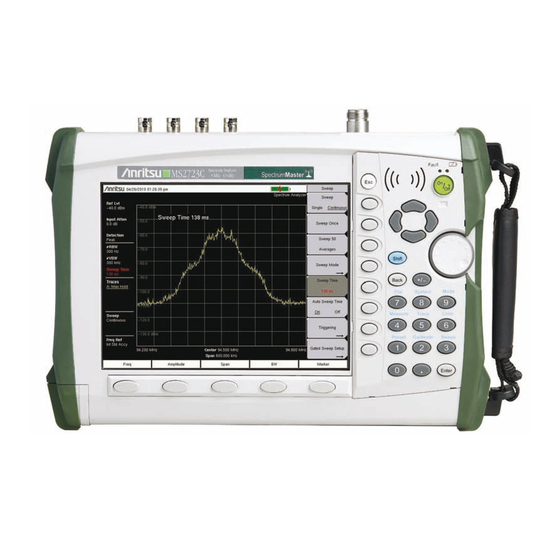
Spectrum Master™
MS2722C, MS2723C, MS2724C, MS2725C and MS2726C
High Performance Handheld Spectrum Analyzer
Appendix A provides a list of supplemental documentation for the
Spectrum Master features and options. The additional documentation
is available as PDF files on the Documentation disc or the Anritsu
Web site.
Anritsu Company
490 Jarvis Drive
Morgan Hill, CA 95037-2809
USA
Part Number: 10580-00277
Revision: E
Published: September 2016
Copyright 2010, 2016 Anritsu Company
Advertisement
Table of Contents

Related Manuals for Anritsu MS2722C


Summary of Contents for Anritsu MS2722C
- Page 1 High Performance Handheld Spectrum Analyzer Appendix A provides a list of supplemental documentation for the Spectrum Master features and options. The additional documentation is available as PDF files on the Documentation disc or the Anritsu Web site. Part Number: 10580-00277...
- Page 2 LIMITATION OF WARRANTY The foregoing warranty does not apply to Anritsu connectors that have failed due to normal wear. Also, the warranty does not apply to defects resulting from improper or inadequate maintenance by the Buyer, unauthorized modification or misuse, or operation outside of the environmental specifications of the product.
- Page 4 This product and its manuals may require an Export License or approval by the government of the product country of origin for re-export from your country. Before you export this product or any of its manuals, please contact Anritsu Company to confirm whether or not these items are export-controlled.
-
Page 7: Safety Symbols
Some or all of the following five symbols may or may not be used on all Anritsu equipment. In addition, there may be other labels attached to products that are not shown in the diagrams in this manual. - Page 8 This equipment is supplied with a rechargeable battery that could potentially leak hazardous compounds into the environment. These hazardous compounds present a risk of injury or loss due to exposure. Anritsu Company recommends removing the battery for long-term storage of the instrument and storing the battery in a leak-proof, plastic container.
-
Page 9: Table Of Contents
..........1-6 1-12 Anritsu Reference Documents ....... . . 1-7 1-13 Anritsu Service Centers . - Page 10 Parameter Setting ..........2-9 Text Entry .
- Page 11 Saving Measurements ........3-10 3-10 Master Software Tools .
- Page 12 Introduction ..........6-1 Setting Up GPS (Option 31) .
-
Page 13: Chapter 1-General Information
Refer to Appendix A, “Measurement Guides”, for additional information. Throughout this manual, these instruments may be referred to as a Spectrum Master or as a model MS2722C, MS2723C, MS2724C, MS2725C, MS2726C, or as model MS272xC.10580-00277 Contacting Anritsu To contact Anritsu, please visit: http://www.anritsu.com/contact.asp... -
Page 14: Available Models
Spectrum Master models and frequency range described in this User Guide. Table 1-1. Spectrum Master Model Model Frequency Range MS2722C Spectrum Analyzer, 9 kHz to 9 GHz MS2723C Spectrum Analyzer, 9 kHz to 13 GHz MS2724C Spectrum Analyzer, 9 kHz to 20 GHz... -
Page 15: Standard And Optional Accessories
Standard and Optional Accessories The Spectrum Master Technical Data Sheet listed in Section 1-1 contains a list and description of available accessories. The data sheet is available on the Anritsu web site: http://www.anritsu.com. Spectrum Master UG PN: 10580-00277 Rev. E... -
Page 16: Additional Documents
Anritsu part numbers. Measurement guides are provided on the Documentation disc that is shipped with the instrument and are also available for download (at no charge) from the Anritsu web site. Refer to section “Anritsu Reference Documents”... -
Page 17: Spectrum Master Specifications
Spectrum Master changes (to insure the best possible measurement results). Although the Spectrum Master does not require daily field calibration, Anritsu Company recommends annual calibration and performance verification by local Anritsu service centers. 1-10 Preventive Maintenance Spectrum Master preventive maintenance consists of cleaning the unit and inspecting and cleaning the RF connectors on the instrument and on all accessories. -
Page 18: Esd Cautions
Operators should exercise practices outlined within industry standards such as JEDEC-625 (EIA-625), MIL-HDBK-263, and MIL-STD-1686, which pertain to ESD and ESDS devices, equipment, and practices. Because these apply to the MS272xC, Anritsu Company recommends that any static charges that may be present be dissipated before connecting coaxial cables or antennas to the MS272xC. -
Page 19: 1-12 Anritsu Reference Documents
Anritsu Reference Documents 1-12 Anritsu Reference Documents The following URL is an Internet link to the Spectrum Master product page. Spectrum Master product page link: http://www.us.anritsu.com/SpectrumMaster A table at the bottom of each Spectrum Master web page presents Internet links to related literature and software. -
Page 20: 1-14 Battery Replacement
Battery Compartment Door Note Use only Anritsu approved batteries, adapters, and chargers with this instrument. The battery that is supplied with the Spectrum Master may need charging before use. The battery can be charged while it is installed in the Spectrum Master by using either the AC-DC Adapter or the 12-Volt DC adapter, or separately in the optional Dual Battery Charger. -
Page 21: 1-15 Soft Carrying Case
Soft Carrying Case 1-15 Soft Carrying Case The instrument can be operated while in the soft carrying case. On the back of the case is a large storage pouch for accessories and supplies. To install the instrument into the soft carrying case: 1. -
Page 22: 1-16 Tilt Bail Stand
Secure-Environment Workplace 1-16 Tilt Bail Stand The attached Tilt Bail can be used for desktop operation. The tilt bail provides a backward tilt for improved stability and air flow. To deploy the tilt bail, pull the bottom of the tilt bail away from the back of the instrument. -
Page 23: Spectrum Master Memory Types
Secure-Environment Workplace Note that when Frequency Blanking is turned on user files can still be stored and saved to an external USB drive, and that frequency information is not blanked in Warning those files. Also, frequency information is not blanked from the SCPI commands that are used to remotely control the instrument. -
Page 24: Erase All User Files In Internal Memory
The Spectrum Master does not currently provide a secure erase feature. In environments where data security is an issue, Anritsu Company recommends that you store your Spectrum Master-created files on an external USB Flash drive that is then securely retained, sanitized, or destroyed after use. -
Page 25: Chapter 2-Instrument Overview
Chapter 2 — Instrument Overview Introduction This chapter provides a brief overview of the Anritsu MS272xC Spectrum Master. The intent of this chapter is to acquaint you with the instrument. To begin using the instrument immediately, go to Chapter 3, “Quick Start Guide”, to find directions for power on, editing,... -
Page 26: Hardware Overview
Hardware Overview Hardware Overview Turning On the MS272xC for the First Time The Anritsu MS272xC Spectrum Master is capable of approximately 2.5 hours of continuous operation from a fully charged, field-replaceable battery (refer to Section “Battery Replacement” on page 1-8 Chapter 1). -
Page 27: Front Panel Overview
Front Panel Overview Front Panel Overview The Spectrum Master menu-driven interface is easy to use and requires little training. Hard keys on the front panel are used to initiate function-specific menus. Five main menu keys are located below the display. These keys vary in function depending upon the selected mode of instrument operation. -
Page 28: Front Panel Keys
Front Panel Keys Other features on the front panel include: Battery Charge LED (Green) The Battery Charge LED flashes if the battery is charging, and remains on steady when the battery is fully charged. Charge Fault LED (Red) The Charge Fault LED remains on under a battery charger fault condition. Fault conditions include a battery cell voltage that is too low to charge or a battery temperature that is outside the temperature range (–5 ºC to +45 ºC) for charging. -
Page 29: Main Menu Keys
Front Panel Keys Back Key Press this key to delete only one character, one number, or the range that is specified by the cursor. +/– Key Press this key to change the sign of numbers that are entered with the number keys. Number Keypad Press these keys to directly input numbers. -
Page 30: Mode Selector Menu
Mode Selector Menu Mode Selector Menu To access the functions under the Mode menu, select the Shift key, then the Mode (9) key. Use the directional arrow keys or the rotary knob to highlight the selection, and press the Enter key to select. The list of modes that appears in this menu will vary depending upon the options that are installed and activated in your instrument. -
Page 31: Secondary Function Menus
Secondary Function Menus Secondary Function Menus Pressing the Shift key and then a number key selects the menu function that is printed in blue characters above the number key (Figure 2-5). Shift Secondary Menu Function “System (8)” Number Keypad Figure 2-5. Keypad and Secondary Function Menus Not all Secondary Function Menus are active in various operation Modes. -
Page 32: Display Overview
MS272xC display. For more detailed key descriptions of the Spectrum Analyzer mode, refer to the Spectrum Analyzer Measurement Guide (Anritsu part number 10580-00244, available on the Documentation disc or the Anritsu web site). Also refer to Appendix A, “Measurement... -
Page 33: Parameter Setting
Parameter Setting Parameter Setting Pop-up list boxes or edit boxes are used to provide selection lists and selection editors. Scroll through a list of items or parameters with the arrow keys or the rotary knob. Select numerical values by scrolling with the arrow keys or rotary knob or by entering the digits directly from the number keypad. - Page 34 Text Entry Lowercase Text Entry Figure 2-7. Text Entry Menu – Lower Case Uppercase Text Entry Figure 2-8. Text Entry Menu – Upper Case 2-10 PN: 10580-00277 Rev. E Spectrum Master UG...
- Page 35 Text Entry Rotary Knob has scrolled to letter “c” Figure 2-9. Text Entry Menu – Selecting Characters Spectrum Master UG PN: 10580-00277 Rev. E 2-11...
-
Page 36: 2-10 Connector Care
Connector Care 2-10 Connector Care Visually inspect connectors for general wear, for cleanliness, and for damage such as bent pins or connector rings. Repair or replace damaged connectors immediately. Dirty connectors can limit the accuracy of your measurements. Damaged connectors can damage the instrument. -
Page 37: Test Panel Connectors
Test Panel Connectors 2-11 Test Panel Connectors The test panel connector is shown in Figure 2-10 and are described in the following text. Fan Exhaust Port Option 31 GPS Antenna Headset Connector Option 89 Jack IF Out Reference Out RF In External External External... - Page 38 Test Panel Connectors USB Interface – Type A The MS272xC Spectrum Master can also be a USB Host and allow various USB Flash Memory devices to be connected to the instrument for storing measurements, setups, and files. USB Interface – Type Mini-B The USB 2.0 interface can be used to connect the MS272xC Spectrum Master directly to a PC.
-
Page 39: 2-12 Symbols And Indicators
Symbols and Indicators RF In 50 Ω Type-N connector (MS2722C, MS2723C, MS2724C) or a 50 Ω Type-K male ruggedized connector (MS2725C, MS2726C). To prevent damage to your instrument, do not use pliers or a plain wrench to tighten the Type-N connector. Do not overtighten the connector. The recommended torque is 12 lbf·in to 15 lbf·in (1.36 N·m to 1.70 N·m). - Page 40 Caution Use only Anritsu-approved batteries, adapters, and chargers with this instrument. The battery symbol is replaced by a red plug body to indicate that the instrument is running from external power and is not charging the battery (or to indicate that the battery is not present).
-
Page 41: 2-13 Firmware Overview
Firmware Overview 2-13 Firmware Overview Main Menu Keys The Spectrum Master menu-driven interface is easy to use and requires little training. The 5 Main Menu keys are located below the measurement display. These 5 keys are used to list function-specific menus in the active menu (submenu labels). These Main Menu keys vary in function based on the selected mode of operation (Shift, Mode (9)). - Page 42 Firmware Overview 2-18 PN: 10580-00277 Rev. E Spectrum Master UG...
-
Page 43: Chapter 3-Quick Start Guide
Chapter 3 — Quick Start Guide Introduction This chapter provides a brief overview of the Anritsu MS272xC Spectrum Master. The intent of this chapter is to provide a starting point for making basic measurement setups. This chapter describes setup, configure frequency, bandwidth, and amplitude before configuring your measurement setups. -
Page 44: Measurement Setup
Measurement Setup Measurement Setup Connect the Input Source Connect the input signal or antenna to the appropriate test connector on the top of the instrument. For connector descriptions, refer to Figure 2-10 on page 2-13. Editing and Entering Values • Parameter values that are ready for editing are displayed in red on the submenu key. After changing the value, press Enter to set the new value. -
Page 45: Set The Measurement Frequency
Set the Measurement Frequency Set the Measurement Frequency Using Start and Stop Frequencies 1. Press the Freq main menu key. 2. Press the Start Freq submenu key. 3. Enter the desired start frequency. When entering a frequency by using the keypad, the submenu key labels change to frequency units: GHz, MHz, kHz, and Hz. - Page 46 Set the Measurement Frequency 4. Press the Span/RBW submenu key to change the ratio of span width to resolution bandwidth. PN: 10580-00277 Rev. E Spectrum Master UG...
-
Page 47: Set The Amplitude
Set the Amplitude Set the Amplitude Press the Amplitude main menu key to display the Amplitude menu. Setting Amplitude Reference Level and Scale Spectrum Analyzer and Interference Analysis Modes To change the current measurement units, press the Units submenu key and Note select the required units from the submenu keys that are presented. -
Page 48: Reference Level Offset For External Loss Or External Gain
Set the Span Reference Level Offset for External Loss or External Gain To obtain accurate measurements, compensate for any external attenuation or gain by using the RL Offset submenu. The compensation factor is in dB. External attenuation can be created by using an external cable or an external high power attenuator, external gain is typically from an amplifier. -
Page 49: Setting Up Limit Lines
Setting Up Limit Lines Setting Up Limit Lines Press the Shift key then the Limit (6) key on the numeric keypad to display the Limit menu. Simple Limit Line Spectrum Analyzer and Interference Analysis Modes 1. Press the Shift key and then the Limit (6) key. 2. -
Page 50: Complex Limit Lines
Setting Up Limit Lines Complex Limit Lines Spectrum Analyzer and Interference Analysis Modes Figure 3-2 shows an example of a complex limit line. After the right half of the limit line was completed, the left half of the limit line was built by pressing the Limit Advanced submenu key and then pressing the Limit Mirror submenu key. -
Page 51: Setting Up Markers
Setting Up Markers Setting Up Markers Press the Marker main menu key to display the Marker menu. Refer to Figure 3-3. Selecting, Activating, and Placing a Marker 1. Press the Marker 1 2 3 4 5 6 submenu key so that the desired marker number is underlined. -
Page 52: Selecting A Measurement Type
Chapter 4, “File Management” for additional information. 3-10 Master Software Tools Anritsu Master Software Tools is a Microsoft Windows compatible program for transferring and editing saved measurements, markers, and limit lines to a PC. Refer to Chapter 7, “Master Software Tools”... -
Page 53: Chapter 4-File Management
Chapter 4 — File Management Introduction This chapter will review the file management features of the Spectrum Master and detail the File menu. The submenus under this menu allow the user to save, recall, copy, and delete files in internal memory or an external USB flash drive. Managing Files Press the Shift key then the File (7) key on the numeric keypad to list the File menu. -
Page 54: Recall Files
Managing Files Recall Files The recall menu enables you to view all the Measurement and Setup files in the internal memory and external USB flash drive. You can sort the recall menu by name, date, or type. You can also select to view only measurement files or setup files by pressing File Type on the Recall dialog box and selecting the file type you want to view. -
Page 55: Copying Files
Managing Files Copying Files The steps below detail copying a file from internal memory to an external flash drive. Select the files to copy in the top window and the location for the files to be copied to in the bottom window (Figure 4-2). - Page 56 Managing Files 4. To display files within a folder, select the folder and press the Enter key or the Right arrow key. The + symbol indicates additional files or folders with the folder (Figure 4-3). To expand the + symbol, highlight the folder and press the Right arrow key.
-
Page 57: Deleting Files
Managing Files Deleting Files Delete a Selected File or Files Press the Delete submenu key. Highlight the file to be deleted with the Up/Down arrow keys. Press the Select or De-Select key. The file will be highlighted in blue when selected. Press the Delete key and Enter to delete the selected file. -
Page 58: File Menu Overview
File Menu Overview File Menu Overview Open this menu by pressing the Shift key, then the File (7) key. File Save Measurement As FileName.spa Save Save Measurement a b c Spectrum d e f Analyzer Save Mode Only g h i Save j k l Save On... -
Page 59: File Menu
File Menu File Menu Key Sequence: File Save Measurement As: This key will save the current setup with a user defined file name. The default file name is changed using the Save submenu. File To change the default file name, press the Save Measurement submenu key Save Measurement As to open the Save dialog box. -
Page 60: Save Menu
File Menu Save Menu Key Sequence: File > Save Text Entry Keys: The top 5 keys are for text entry. The submenu keys for Text Entry displays the characters (alphabet, hyphen, and underscore). Press Save submenu key (for example) to open another submenu with a a b c / d e f a b c separate key for each of these letters. -
Page 61: Save Location Menu
File Menu Save Location Menu Key Sequence: File > Save > Change Save Location This menu and dialog box is used to create folders and select where the Spectrum Master will save the current file. Select folders or drives with the Save Location Up/Down keys or the rotary knob. -
Page 62: Save On Event Menu
File Menu Save On Event Menu Key Sequence: File > Save On Event This menu is used to auto save measurements to internal memory after: Save On..Crossing Limit: Toggling this submenu key to On will save the measurement to internal memory when the measurement has crossed ...Crossing Limit a defined limit line created with the Limit menu. -
Page 63: Recall Menu
File Menu Recall Menu Key Sequence: File > Recall This menu and dialog box is used to create folders and select where the Spectrum Master will save the current file. Select folders or drives with the Recall Up/Down keys or the rotary knob. Sort By Sort By: Press this submenu key to sort file and folders by the Name... -
Page 64: Copy Menu
File Menu Copy Menu Key Sequence: File > Copy This menu and dialog box is used to copy folders and files. Select folders or files with the Up/Down keys or the rotary knob. Figure 4-2 on page 4-3 Copy shows the Copy dialog box with two Jpeg images selected and ready to be Sort By copied to the USB flash drive. -
Page 65: Delete Menu
File Menu Delete Menu Key Sequence: File > Delete This menu and dialog box is used to delete folders and files. Select folders or files with the Up/Down keys or the rotary knob. Delete Sort By: Press this submenu key to sort files and folders by name, by Sort By the type of file, or by the date that the file or folder was saved. - Page 66 4-14 PN: 10580-00277 Rev. E Spectrum Master UG...
-
Page 67: Chapter 5-System Operation
Chapter 5 — System Operation Introduction This chapter reviews the Spectrum Master system operations. The other menus (Sweep, Measure, Trace, and Limit) are described in the Measurement Guides that are listed in Appendix Spectrum Master UG PN: 10580-00277 Rev. E... -
Page 68: System Menu Overview
System Menu Overview System Menu Overview To access the functions under the System menu, press the Shift key, then the System (8) key. Menu maps typically display all possible submenu keys, although some keys are displayed on the instruments only under special circumstances (refer to menu descriptions on the following pages). -
Page 69: System Menu
Enter key to continue. The display lists a summary of those tests Application that have passed. If any test fails, then all of the performed tests are listed with Pass/Fail notification. If any test fails, then contact your Anritsu Service Options Center and report the test results (refer to “Anritsu Service Centers”... -
Page 70: System Options Menu
System Menu System Options Menu Key Sequence: Shift, System (8) > System Options Date & Time: Press this submenu key to display a dialog box for setting the current date and time. Use the submenu keys or the Left/Right arrow keys to System Options select the field to be modified. -
Page 71: System Options 2/2 Menu
System Menu System Options 2/2 Menu Key Sequence: Shift, System (8) > System Options > More Share CF & Pwr Offset All Modes Not Shared: Press this submenu key to toggle the setting to System Options 2/2 All Modes or to Not Shared. Select All Modes to have the current center fre- Share CF &... -
Page 72: Display Settings Menu
System Menu Display Settings Menu Key Sequence: Shift, System (8) > System Options > Display Brightness: The brightness of the display can be adjusted to optimize viewing under a wide variety of lighting conditions. Use the keypad, the Display Settings Up/Down arrow keys or the rotary knob to select a brightness level from 1 to 9, with 9 being the brightest. -
Page 73: Reset Menu
Note: This same reset sequence can be initiated when turning the Spectrum Master On by pressing and holding the System (8)+On keys until the Anritsu splash screen is displayed. Back Update Firmware: Press this submenu key to update the instrument operating system using an external USB drive. -
Page 74: Preset Menu
If the Spectrum Master is within the specified operating range with a charged battery, and if the self test fails, then contact your Anritsu Service Center. To initiate a self test when the system is already powered up: 1. -
Page 75: Update Firmware
Update Firmware Update Firmware Using a USB Memory Device The Spectrum Master contains a feature that allows you to update its firmware by using a USB memory device. First, you must load the USB memory device with the firmware using Master Software Tools (MST). - Page 76 Figure 5-10. Firmware Update Menu 5. Highlight each of the save choices: Save None, Save User Data, and Save & Restore User Data. Read through each choice carefully and then select the desired save mode. • Save None: No attempt will be made to save any user data. •...
-
Page 77: Update Firmware Using Master Software Tools
Update Firmware 7. The Firmware Update dialog will query you to confirm the process by pressing Enter to continue or Esc to abort (Figure 5-11). Figure 5-11. Firmware Update Menu 8. Select Enter and the firmware update process begins. The Firmware Update dialog displays the following message: Updating firmware. - Page 78 Update Firmware 5-12 PN: 10580-00277 Rev. E Spectrum Master UG...
-
Page 79: Chapter 6-Gps (Option 31)
In order to acquire data from the GPS satellites, you must have line-of-sight to the satellites, or the antenna must be placed outside without any obstructions. In addition to Option 31, the Spectrum Master requires a GPS antenna, Anritsu part number 2000-1528-R. Activating the GPS Feature 1. - Page 80 In order to acquire data from the GPS satellites, you must have line-of-sight to the satellites, or the antenna must be placed outside with no obstructions. Option 31 requires a GPS antenna, Anritsu part number 2000-1528-R. PN: 10580-00277 Rev. E...
-
Page 81: Chapter 7-Master Software Tools
“Updating Instrument Firmware” on page 7-2 Master Software Tools Overview Anritsu Master Software Tools is a Microsoft Windows compatible program (for Windows 2000, Windows XP, and 64-bit Windows Vista) for transferring and editing saved measurements, markers, and limit lines to a PC. Master Software Tools will not function on earlier versions of the Microsoft Windows operating system. -
Page 82: Installing Mst
Updating Instrument Firmware The 3D Spectrogram function allows you to view a folder of measurement traces in true three dimensions: frequency, time, and amplitude. You can use markers to select or point out specific frequencies and amplitudes. With Signal ID, you can view specific types of signals and their signal-to-noise ratio (SNR). - Page 83 7-4, the status of the highlighted file is Available, and the Install to Unit button is gray and inactive. This means that the updated file is on the Anritsu Product Support Web site and needs to be downloaded to your PC. After the file has been downloaded and placed on your PC, its status changes to Ready, and the Install to Unit button becomes active.
- Page 84 Updating Instrument Firmware Screen captured images are provided as examples. The images shown on your Note instrument may differ from the examples in this user guide. Figure 7-3. Product Updates Window: Status Ready PN: 10580-00277 Rev. E Spectrum Master UG...
- Page 85 Updating Instrument Firmware Figure 7-4. Product Updates Window: Status Available File Status Ready: 1. Check that the file status is Ready and that the Install to Unit button is active. 2. Click the Install to Unit button. Your Spectrum Master is updated with the new firmware.
-
Page 86: Update Firmware By Using A Usb Device
1. Click the Check for Updates button. Master Software Tools checks for the latest updates at the Anritsu Product Support Web Site. New updates that are found are listed in the file menu. 2. Click the Retrieve File button. The file is transferred from the Web site to your PC. -
Page 87: Appendix A-Measurement Guides
This appendix provides a list of supplemental documentation for Spectrum Master features and options. The measurement guides are available as PDF files on the Documentation disc or the Anritsu web site. The Technical Data Sheets are available on the Anritsu web site. Documents, Firmware, Supplemental Information Documents and Firmware may also be downloaded. -
Page 88: Documents, Firmware, Supplemental Information
IEEE 802.16 Mobile WiMAX RF Signal Analyzer (0066) Measurement Guide (10580-00236) IEEE 802.16 Mobile WiMAX Demodulated Signal Analyzer (0067) IEEE 802.16 Mobile WiMAX Over-the-Air Signal Analyzer (0037) Performance Specifications, Spectrum Master Technical Data Sheets MS2722C 11410-00529 MS2723C 11410-00524 MS2724C 11410-00525... - Page 89 Documents, Firmware, Supplemental Information Table A-3. Additional Instrument Supplements Supplement Type Part Number Handheld Instruments Documentation Disc 10920-00060 Computer Software Application Master Software Tools CD-ROM 2300-498 (May also be downloaded) Spectrum Master UG PN: 10580-00277 Rev. E...
- Page 90 Documents, Firmware, Supplemental Information PN: 10580-00277 Rev. E Spectrum Master UG...
-
Page 91: Appendix B-Error Messages
Caution: Use of MASTER RESET, System+ON, will erase all user saved setups and measurement traces and return the unit to a fully Factory Default condition. If the error persists, then contact your Anritsu Service Center. DDC FAILED The Digital Down Converter failed to return a value. Insure that the battery level is adequate for operation or that temperature is within acceptable limits. -
Page 92: Operation Error Messages
See the accessories section for a list of available band pass filters from Anritsu. Out of band frequencies can often be detected by increasing the Span to maximum in the peak detect mode of operation. Another resolution may be to reset to factory defaults with either Factory Defaults, ESC+ON, or MASTER RESET, System+ON. - Page 93 MASTER RESET, System+ON, will erase all user saved setups and measurement traces and return the unit to a fully Factory Default condition. If the error persists, then contact your Anritsu Service Center. Trace not saved. Please wait for complete sweep and try again.
- Page 94 Caution: Use of MASTER RESET, System+ON, will erase all user saved setups and measurement traces and return the unit to a fully Factory Default condition. If the error persists, then contact your Anritsu Service Center. PN: 10580-00277 Rev. E Spectrum Master UG...
- Page 95 MASTER RESET, System+ON. Caution: Use of MASTER RESET, System+ON, will erase all user saved setups and measurement traces and return the unit to a fully Factory Default condition. If the error persists, then contact your Anritsu Service Center. Spectrum Master UG...
- Page 96 Defaults, ESC+ON, or MASTER RESET, System+ON. Caution: Use of MASTER RESET, System+ON, will erase all user saved setups and measurement traces and return the unit to a fully Factory Default condition. If the error persists, then contact your Anritsu Service Center.
- Page 97 Factory Defaults, ESC+ON. Caution: Use of MASTER RESET, System+ON, will erase all user saved setups and measurement traces and return the unit to a fully Factory Default condition. If the error persists, then contact your Anritsu Service Center.
- Page 98 Operation Error Messages PN: 10580-00277 Rev. E Spectrum Master UG...
-
Page 99: Appendix C-Lan And Dhcp
Appendix C — LAN and DHCP Introduction This appendix describes network connections for the MS272xC Spectrum Master. Ethernet Configuration LAN Connection The RJ-45 connector is used to connect the Spectrum Master to a local area network. Integrated into this connector are two LEDs. The amber LED shows the presence of a 10 Mbit/s LAN connection when on, and a 100 Mbit/s LAN connection when off. -
Page 100: Ethernet Configuration
Ethernet Configuration To display the IP address with the instrument on, press the Shift key, then the System (8) key, then the submenu key and the submenu key. The IP address System Options Ethernet Config will be displayed as shown in Figure C-1. -
Page 101: Ethernet Config
Ethernet Configuration Ethernet Config Press this submenu key to display the Ethernet submenu and to open the Ethernet Editor dialog box in order to set the IP address of the instrument. Figure C-2. Setting IP Address Manually Spectrum Master UG PN: 10580-00277 Rev. -
Page 102: Ethernet Menu
Ethernet Configuration Ethernet Menu Key Sequence: Shift, System (8) > System Options > Ethernet Config Type Manual DHCP: Press this submenu key to select whether the address will Ethernet be entered manually, or will be supplied automatically by a network DHCP Type server. -
Page 103: Dhcp
DHCP DHCP DHCP stands for Dynamic Host Configuration Protocol. It is a protocol that allows a server to dynamically assign IP addresses to devices that are connected to the network. Most networks include a DHCP server to manage IP addresses. When a DHCP server is available on the network, DHCP is the preferred IP address assignment mode. -
Page 104: Example 2
Windows 2000 IP Configuration Ethernet adapter Local Area Connection: Connection-specific DNS Suffix. : us.anritsu.com IP Address... . : 172.26.202.172 Subnet Mask ... : 255.255.252.0 Default Gateway . -
Page 105: Ping Tool
Ping Tool Ping Tool Another tool that can find out if a selected IP address is already on the network is ping. Ping is a harmless way to determine if an address is found on the network, and (if it is found) to receive a reply. - Page 106 PN: 10580-00277 Rev. E Spectrum Master UG...
- Page 107 ..... 5-6 Anritsu, contact ....1-1...
- Page 108 ..2-14 contacting Anritsu ... . . 1-1 range ......1-2 MS2722C product page .
-
Page 109: Updating Firmware
USB ....5-9, 7-2 reset URL contacting Anritsu ... . 1-1 files erased ....1-12 menu . - Page 110 W to W web links website, contacting Anritsu ..1-1 MS2722C product page ..1-1 windows operating system support, MST 7-1 Index-4 PN: 10580-00277 Rev. E...
- Page 112 Anritsu Company 490 Jarvis Drive Anritsu prints on recycled paper with vegetable soybean oil ink. Morgan Hill, CA 95037-2809...
Need help?
Do you have a question about the MS2722C and is the answer not in the manual?
Questions and answers