
Subscribe to Our Youtube Channel
Related Manuals for CVW SWIFT 800


Summary of Contents for CVW SWIFT 800
- Page 1 SWIFT 800 --Wireless HD Video USER MANUAL This user manual applies to: Transmitter: 7072 Receiver: 3072 Version: 1.0 2019.01.11...
-
Page 3: Table Of Contents
CONTENTS Foreword Brief Introduction Features Packing List Structure & Interface The Transmitter 7072 The Receiver 3072 Product Installation Digital Tube Status Indication Operating Instructions Application Case Product Specifications Troubleshooting... -
Page 4: Foreword
Wireless transmission distance up to 800ft; Foreword Support P frame / I frame adaptation to ensure ultra-low latency of - Please read this manual carefully before you use this product and retain it video transmission; properly for future reference Support low-battery alarm function of the battery; - If there is any doubt or difficulty in the process of product usage, please feel Full hardware design, no need to install software, PNP, free to contact us or the dealer. -
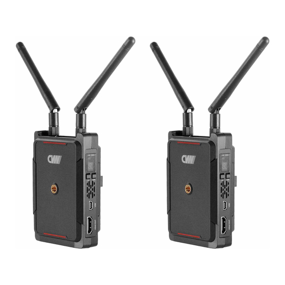
Page 5: Structure & Interface
Structure & Interface Transmitter 7072 Interface Introduction Transmitter:7072 1. Link indicator: Used to indicate the network working status of the product. 2. Video indicator: Link indicator Video indicator Antenna interface Used to indicate the video transmission working status of the product. 3. - Page 6 Receiver 3072 Interface Introduction Receiver:3072 1. Link indicator: Used to indicate the network working status of the product. Link indicator Video indicator Antenna interface 2. Video indicator: Used to indicate the video transmission working status of the product. 3. Digital LED: Digital LED Used to display the current working channel of the receiver.
-
Page 7: Product Installation
Product Installation 3. The transmitter is mounted on a SLR camera and rotated clockwise. Connect the HDMI interface of the transmitter to the HDMI interface of the 7072 Wireless HD Transmitter SLR camera via the HDMI cable (as shown in the figure). Installation Instructions 4. - Page 8 3072 Wireless HD Receiver 3. Install the receiver on the monitor. Connect the HDMI cable. Installation Instructions Turn on the power (receiver and monitor power). 1. Install the antennas on the receiver, turn it clockwise, and tighten the antennas. Adjust the direction of the receiver antennas to assume an upright parallel state (as shown in the figure).
-
Page 9: Digital Tube Status Indication
Digital Tube Status Indication Operating Instructions Transmitter / Receiver Digital Tube Status 1. Button function definition: LINK indicator VIDEO indicator Channel button (CH): channel switching function Mode button (Mode): Mode switching function 2. Operating instructions: Frequency channel setting, short press CH button to switch the operating frequency channel;... -
Page 10: Application Case
Application Case Connecting to transmitter... channel 1. Set the transmitter and receiver to the same frequency 2. The transmitter and HD source device are connected and powered by the HDMI cable. OSD display 3. The receiver and monitor are connected via an HDMI cable. 5. -
Page 11: Product Specifications
Troubleshooting Product Specifications Issue Troubles & Possible Reasons Solution The transmitter is not powered. Turn on the transmitter power. 7072 3072 Item The transmitter or receiver is not Insert the transmitter or receiver placed upright. into the base and keep it upright. Frequency 5.10~5.90 (GHz) The distance between the receiver... - Page 12 FCC Statement This equipment has been tested and found to comply with the limits for a Class B digital Issue Troubles & Possible Reasons Solution device, pursuant to part 15 of the FCC rules. These limits are designed to provide reasonable The transmitter or receiver is not Insert the transmitter or receiver into the base placed upright.
Need help?
Do you have a question about the SWIFT 800 and is the answer not in the manual?
Questions and answers