
Subscribe to Our Youtube Channel
Related Manuals for FiberHome AN5506-01-A


Summary of Contents for FiberHome AN5506-01-A
- Page 1 An Expert in Optical Communications Product Manual AN5506-01 / 02 Series GPON Optical Network Unit Version: A Code: MN000002300 Date: June 2015 FiberHome Telecommunication Technologies Co., Ltd.
- Page 2 Version Version Description Initial version. are trademarks of FiberHome Telecommunication Technologies Co., Ltd. (Hereinafter referred to as FiberHome) All brand names and product names used in this document are used for identification purposes only and are trademarks or registered trademarks of their respective holders.
-
Page 3: Table Of Contents
Contents 1 Safety Precautions ............. 1 2 Product Specification ............2 3 Product Overview ............... 3 3.1 Introduction to the AN5506-01-A ........3 3.2 Introduction to the AN5506-01-B ........10 3.3 Introduction to the AN5506-02-A ........15 3.4 Introduction to the AN5506-02-B ........20 4 Web Configuration Guide .......... - Page 4 4.5 Application ..............53 4.5.1 DDNS ..............54 4.5.2 Port Forwarding..........55 4.5.3 NAT ..............56 4.5.4 Network Diagnosis ..........58 4.6 Management ..............58 4.6.1 User Management..........59 4.6.2 Equipment Management........60 4.6.3 Log ..............63 5 Handling Common Problems ........65 5.1 Power Supply Status Indicator LED OFF.......65 5.2 Register Status Indicator LED OFF .......65 5.3 Optical Signal Status Indicator LED ON or Blinking..65 5.4 Ethernet Interface Status Indicator LED OFF....66...
-
Page 5: Safety Precautions
1 Safety Precautions 1 Safety Precautions For your correct and safe operations on the equipment, please read carefully and strictly observe the following safety instructions: High optical power can cause bodily harm, especially to eyes. Never look directly into the end of the optical transmitter fiber jumper or the end of its active connector. -
Page 6: Product Specification
Table 2.1 Interfaces Supported by the ONUs Ethernet Interface Phone Interface ONU Type Quantity Quantity 1 (GE) AN5506-01-A 1 (GE) AN5506-01-B 2 (GE) AN5506-02-A 2 (GE) AN5506-02-B Table 2.2 lists the service types supported by the AN5506-01 / 02 Series ONUs. -
Page 7: Product Overview
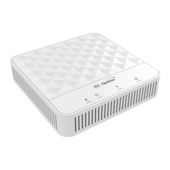
LEDs of the AN5506-01 / 02 Series series ONUs. 3.1 Introduction to the AN5506-01-A The AN5506-01-A is an FTTH GPON ONU. It provides users with communication and entertainment services in the form of data, video, and so on, to meet the integrated access demand of families and small-scaled enterprises. - Page 8 3 Product Overview Figure 3.1 Overall Appearance of the AN5506-01-A The rear panel of the AN5506-01-A is shown in Figure 3.2. Figure 3.2 Rear Panel of the AN5506-01-A The side panel of the AN5506-01-A is shown in Figure 3.3. Figure 3.3...
- Page 9 3 Product Overview Equipment Specifications The AN5506-01-A specifications include technical parameters and specifications. Table 3.1 shows the technical parameters. Table 3.2 and Table 3.3 show the specifications. Table 3.1 Technical Parameters of the AN5506-01-A Type Description Item Supports the IEEE 802.1Q VLAN standard.
- Page 10 3 Product Overview Table 3.1 Technical Parameters of the AN5506-01-A (Continued) Type Description Item Supports the ACL function to match traffic based on the ACL rules. Supports global configuration of queue priority and flexible mapping of 802.1p values in packets.
- Page 11 3 Product Overview Table 3.2 Specifications of the AN5506-01-A6G (Continued) Type Description Item Power consumption parameters Operating to 45 temperature Environment Storage to 70 parameters temperature Environmental 10% to 95% (no condensation) humidity Table 3.3 Specifications of the AN5506-01-A9G Type Description Item 23.5mm ×...
- Page 12 3 Product Overview Indicator LED Description See Table 3.4 and Table 3.5 for the description of indicator LEDs on the AN5506-01-A. Table 3.4 Description of Indicator LEDs on the AN5506-01-A6G Indica- Meaning Status Description Color Status tor LED Register The ONU is activated.
- Page 13 3 Product Overview Table 3.5 Description of Indicator LEDs on the AN5506-01-A9G Indica- Meaning Status Description Color Status tor LED Register The ONU is activated. status Blinking The ONU is being activated. Green indicator The ONU is not activated. The power supply for the PON port optical module of the ONU Optical is shut down.
-
Page 14: Introduction To The An5506-01-B
3 Product Overview 3.2 Introduction to the AN5506-01-B The AN5506-01-B is an FTTH GPON ONU. It provides users with communication and entertainment services in the form of data, voice, video, and so on, to meet the integrated access demand of families and small-scaled enterprises. - Page 15 3 Product Overview Figure 3.5 Rear Panel of the AN5506-01-B The side panel of the AN5506-01-B is shown in Figure 3.6. Figure 3.6 Side Panel of the AN5506-01-B Equipment Specifications The AN5506-01-B specifications include technical parameters and specifications. Table 3.6 shows the technical parameters. Table 3.7 shows the specifications.
- Page 16 3 Product Overview Table 3.6 Technical Parameters of the AN5506-01-B (Continued) Type Description Item Supports the IPv4/v6 dual stack. Supports the packet filtering, MAC address filtering and URL filtering. Supports protection against illegal message (DoS, ARP) attacks; supports suppression of broadcast storms. Supports obtaining the user IP address in the DHCP mode;...
- Page 17 3 Product Overview Table 3.6 Technical Parameters of the AN5506-01-B (Continued) Type Description Item Supports Class B+, with receiving sensitivity less than -29 dBm. Provides one LAN interface (RJ-45 interface), supporting full-duplex or half- duplex and 10 / 100 / 1000 Mbit/s auto LAN interface negotiation.
- Page 18 3 Product Overview Table 3.7 Specifications of the AN5506-01-B (Continued) Type Description Item Environmental 10% to 95% (no condensation) humidity Indicator LED Description See Table 3.8 for the description of indicator LEDs on the AN5506- 01-B. Table 3.8 Description of Indicator LEDs on the AN5506-01-B Indica- Meaning Status Description...
-
Page 19: Introduction To The An5506-02-A
3 Product Overview Table 3.8 Description of Indicator LEDs on the AN5506-01-B (Continued) Indica- Meaning Status Description Color Status tor LED The interface is not connected to the user terminal. Power The ONU is powered on. status Power Green indicator The ONU is not powered on. - Page 20 3 Product Overview Figure 3.7 Overall Appearance of the AN5506-02-A The rear panel of the AN5506-02-A is shown in Figure 3.8. Figure 3.8 Rear Panel of the AN5506-02-A The side panel of the AN5506-02-A is shown in Figure 3.9. Figure 3.9 Side Panel of the AN5506-02-A...
- Page 21 3 Product Overview Equipment Specifications The AN5506-02-A specifications include technical parameters and specifications. Table 3.9 shows the technical parameters. Table 3.10 shows the specifications. Table 3.9 Technical Parameters of the AN5506-02-A Type Description Item Supports the IEEE 802.1Q VLAN standard. Supports joining the 802.1Q VLAN in the VLAN tag / untag mode.
- Page 22 3 Product Overview Table 3.9 Technical Parameters of the AN5506-02-A (Continued) Type Description Item Supports the ACL function to match traffic based on the ACL rules. Supports global configuration of queue priority and flexible mapping of 802.1p values in packets. Supports three queue scheduling modes (PQ, WRR and PQ+WRR);...
- Page 23 3 Product Overview Table 3.10 Specifications of the AN5506-02-A (Continued) Type Description Item Weight About 138g Power supply DC 12 V/0.5 A parameters Power consumption parameters Operating to 45 temperature Environment Storage to 70 parameters temperature Environmental 10% to 95% (no condensation) humidity Indicator LED Description See Table 3.11 for the description of indicator LEDs on the AN5506-...
-
Page 24: Introduction To The An5506-02-B
3 Product Overview Table 3.11 Description of Indicator LEDs on the AN5506-02-A (Continued) Indica- Meaning Status Description Color Status tor LED The interface is connected to the user terminal and no data Ethernet are transmitted. interface Ethernet The interface is transmitting / status Green port... - Page 25 3 Product Overview Figure 3.10 Overall Appearance of the AN5506-02-B The rear panel of the AN5506-02-B is shown in Figure 3.11. Figure 3.11 Rear Panel of the AN5506-02-B The side panel of the AN5506-02-B is shown in Figure 3.12. Figure 3.12 Side Panel of the AN5506-02-B...
- Page 26 3 Product Overview Equipment Specifications The AN5506-02-B specifications include technical parameters and specifications. Table 3.12 shows the technical parameters. Table 3.13 shows the specifications. Table 3.12 Technical Parameters of the AN5506-02-B Type Description Item Supports the IEEE 802.1Q VLAN standard. Supports joining the 802.1Q VLAN in the tag VLAN / untag mode.
- Page 27 3 Product Overview Table 3.12 Technical Parameters of the AN5506-02-B (Continued) Type Description Item Supports the ACL function to match traffic based on the ACL rules. Supports global configuration of queue priority and flexible mapping of 802.1p values in packets. Supports three queue scheduling modes (PQ, WRR and PQ+WRR);...
- Page 28 3 Product Overview Table 3.13 Specifications of the AN5506-02-B (Continued) Type Description Item Wall mounting 75mm hole distance Weight About 141g Power supply DC 12 V/1 A parameters Power consump- tion parameters Operating to 45 temperature Environ- Storage ment to 70 temperature parameters Environmental...
- Page 29 3 Product Overview Table 3.14 Description of Indicator LEDs on the AN5506-02-B (Continued) Indica- Meaning Status Description Color Status tor LED Optical The ONU has not received the Blinking signal optical signal. status The ONU has received the indicator optical signal. The port is registered in the Phone softswitch system.
-
Page 30: Web Configuration Guide
4 Web Configuration Guide 4 Web Configuration Guide The following introduces the Web GUI of the AN5506-01 / 02 Series ONU administrator, including the parameter meanings and operation methods. Tip: Configure the ONU using the access network management system on the OLT. Refer to the corresponding OLT configuration guide. 4.1 Logging into the Web GUI Locally The following discusses how to log into the ONU Web GUI locally and introduces the configuration GUI layout. - Page 31 4 Web Configuration Guide Table 4.1 Planning Data for Logging into the Web GUI Locally (Continued) Description Item Common user User name: useradmin Password: user1234 Note: Some operators customized the user name and password, so that the default user name and password may have been modified.
- Page 32 4 Web Configuration Guide Click Local Area Connection to bring up the Local Area Connection Properties, and click Properties. In the Local Area Connection Properties dialog box, double-click Internet Protocol 4 (TCP/IPv4).
- Page 33 4 Web Configuration Guide In the Internet Protocol 4 (TCP/IPv4) Properties dialog box, set the IP address and subnet mask of the computer. (See Table 4.1 for the detailed values).
- Page 34 4 Web Configuration Guide Click the OK button to save the configuration. The operation method of the Windows XP operating system is described as follows: In the Windows taskbar, select Start Control Panel. Double-click Network Connection to enter the network connection window. Right-click Local Connection and select Properties from the shortcut menu to bring up the Local Connection Properties dialog box.
- Page 35 4 Web Configuration Guide Click the OK button to save the configuration. Enter http://192.168.1.1 (default management IP address of the ONU) in the browser address bar in the computer, and press the Enter key to bring up the user login dialog box. Enter the administrator user name and password in the login dialog box.
- Page 36 4 Web Configuration Guide Configuration management area. Displays the corresponding content of the selected navigation bar and link bar. (1) Navigation bar (2) Link bar (3) Configuration management area Figure 4.1 Web Configuration GUI The Web GUI configuration is basically the same for the AN5506-01 / 02 Series ONUs.
-
Page 37: Status
4 Web Configuration Guide 4.2 Status The following introduces how to view the basic information of the ONU in the Web GUI, including the equipment information, WAN side status, LAN side status, and optical power status. 4.2.1 Equipment Information Select "State" in the navigation bar and select "Device Information" in the left link bar to view the information such as the product name, hardware version and software version. -
Page 38: Lan Side Status
4 Web Configuration Guide Figure 4.3 WAN Side Status 4.2.3 LAN Side Status Check the state information about the LAN interface and the DHCP client end. LAN Side Status Select State in the navigation bar and select Lan State Lan State in the left link bar to view the information such as the IP address, subnet mask, service type and status of the LAN side. -
Page 39: Optical Power Status
4 Web Configuration Guide Figure 4.5 DHCP User List 4.2.4 Optical Power Status Select State in the navigation bar and select Optical Power in the left link bar to view the optical module information such as the Tx optical power, Rx optical power and working temperature. See Figure 4.6. -
Page 40: Broadband Setting
4 Web Configuration Guide Select Network in the navigation bar and select LAN Settings LAN Settings in the left link bar to open the LAN settings tab, as shown in Figure 4.7. Figure 4.7 LAN Settings Configure the management IP address and subnet mask at the LAN side. - Page 41 4 Web Configuration Guide Figure 4.8 Broadband Settings Configure the parameters related to the broadband at the WAN side. Table 4.3 describes the parameters. Click Apply to save and apply the configuration. Table 4.3 Parameters for Broadband Settings Description Item Enables or disables the WAN connection.
- Page 42 4 Web Configuration Guide Table 4.3 Parameters for Broadband Settings (Continued) Description Item TR069_INTERNET: this connection is applicable for both TR069 and Internet access. Other: other connection. VOIP: this connection is only applicable for voice application. VOIP_INTERNET: this connection is applicable for voice and Internet access.
- Page 43 4 Web Configuration Guide Table 4.3 Parameters for Broadband Settings (Continued) Description Item Users need to configure this item when the service type is set to INTERNET, IP Mode Select IPv4 or IPv4&IPv6. TR069_INTERNET or VOIP_INTERNET and the connection type is set to Route.
- Page 44 4 Web Configuration Guide Table 4.3 Parameters for Broadband Settings (Continued) Description Item the Internet and generates traffic, the ONU dials automatically to connect. When the subscriber is idle and no traffic exists, the ONU will stop dialing automatically after the set disconnection time interval expires.
-
Page 45: Dhcp Server
4 Web Configuration Guide Table 4.3 Parameters for Broadband Settings (Continued) Description Item Enter the IP address of the standby Secondary DNS server provided by ISP. DNS Server Enter the static IPv6 address prefix IPv6 Prefix at the WAN side provided by the ISP. - Page 46 4 Web Configuration Guide Figure 4.9 DHCP Server Configure the DHCP server parameters as required. Table 4.4 describes the parameters. Click Apply to save the configuration information. The configuration will take effect after the ONU is rebooted. Table 4.4 Parameters for the DHCP Server Description Item Enables or disables the DHCP server.
-
Page 47: Authentication Setting
4 Web Configuration Guide Table 4.4 Parameters for the DHCP Server (Continued) Description Item DHCP Subnet The mask of the active DHCP server. Mask DHCP The IP address of the active DNS server provided by ISP. Primary DHCP The IP address of the standby DNS server provided by ISP. Secondary DHCP Default... -
Page 48: Security
4 Web Configuration Guide Select Network in the navigation bar and select OLT Authentication in the left link bar to open the OLT authentication configuration tab, as shown in Figure 4.10. Figure 4.10 OLT Authentication Configure the parameters as required. Table 4.5 describes the parameters. -
Page 49: Firewall
4 Web Configuration Guide 4.4.1 Firewall The firewall configuration covers the following items: Firewall enabling IP filtering URL filtering Anti-port scan MAC address filtering 4.4.1.1 Firewall Enabling Enabling firewall can prevent the malicious access to the WAN port of the ONU. Select Security in the navigation bar and select Firewall Firewall Enable in the left link bar to open the firewall enabling tab, as shown in Figure 4.11. - Page 50 4 Web Configuration Guide Select Security in the navigation bar and select Firewall IP Filtering in the left link bar. Click Add to open the filtering rule list configuration tab, as shown in Figure 4.12. Figure 4.12 IP Filtering Configure the parameters relevant to filtering as required. Table 4.6 describes the parameters.
-
Page 51: Url Filtering
4 Web Configuration Guide Table 4.6 Parameters for IP Address Filtering (Continued) Description Item Whitelist indicates that the data complying with the rules in the filtering rule table will be allowed to pass. Blacklist indicates that the data complying with the rules in the filtering rule table will not be allowed to pass. - Page 52 4 Web Configuration Guide Select Security in the navigation bar and select Firewall URL Filtering in the left link bar, and then click Add to open the URL filtering table configuration tab, as shown in Figure 4.13. Figure 4.13 URL Filtering Configure the parameters relevant to filtering as required.
- Page 53 4 Web Configuration Guide Table 4.7 Parameters for URL Filtering Parameters (Continued) Item Description complying with the rules defined in the filtering rule table will not be allowed to pass. The URL address accessed by users. Address The starting time of the filtering rule. Start Time The ending time of the filtering rule.
-
Page 54: Mac Address Filtering
4 Web Configuration Guide 4.4.1.5 MAC Address Filtering One user device may have multiple IP addresses but only one MAC address. The user device access authority in the LAN can be controlled effectively by setting the MAC address filtering. After the fire wall is enabled, the pre-set rules will take effect, and the MAC addresses that meet the filtering conditions will be filtered. -
Page 55: Remote Control
4 Web Configuration Guide Table 4.8 Parameters for MAC Address Filtering Item Description Enables or disables the MAC address Filtering filtering function. Enable Select the filtering mode. The white list and black list modes are global configuration, After setting, which cannot be enabled simultaneously. click the Apply Whitelist indicates that the data button to... -
Page 56: Ddos
4 Web Configuration Guide Select Security in the navigation bar and select Remote Control in the left link bar to open the remote control configuration tab, as shown in Figure 4.16. Figure 4.16 Remote Control Enable or Disable the remote access control as required. Click Apply to save and apply the configuration. -
Page 57: Https
4 Web Configuration Guide 4.4.4 HTTPS The ONU provides the HTTPS function. The HTTPS is the HTTP channel for security. It is built on the SSL+HTTP protocol, which can perform encryption transmission and identity authentication. Select Security in the navigation bar and select HTTPS in the left link bar to open the HTTPS function configuration tab, as shown in Figure 4.18. -
Page 58: Ddns
4 Web Configuration Guide 4.5.1 DDNS The DDNS server transforms the dynamic IP address at the WAN side of the ONU into a static domain name. Users from Internet can easily access the gateway using this domain name. Select Application in the navigation bar and select DDNS in the left link bar to open the DDNS configuration tab, as shown in Figure 4.19. -
Page 59: Port Forwarding
4 Web Configuration Guide 4.5.2 Port Forwarding The port forwarding can create the mapping relation between the WAN port IP address / common port number and the LAN server IP address / private port number. In this way, all the accesses to a certain service port at this WAN port will be re-directed to the corresponding port of the server in the designated LAN. -
Page 60: Nat
4 Web Configuration Guide Table 4.10 Parameters for Port Forwarding (Continued) Item Description Description The port forwarding rule name. The range of ports for Extranet data packets. If only one Public Port port exists, enter the same port number. The IP address of the LAN virtual server for port forwarding. - Page 61 4 Web Configuration Guide Figure 4.21 Configure relevant parameters according to the requirement. Table 4.11 describes the parameters. Click Apply to apply and save the configuration. Table 4.11 Parameters for NAT Configuration Item Description The corresponding WAN connection bound with the NAT rule.
-
Page 62: Network Diagnosis
4 Web Configuration Guide 4.5.4 Network Diagnosis The ONU provides two network diagnosis tools. Ping test: Test whether the router is normally connected with the target host or another device. Traceroute test: Check the routing condition from the router to the target host. -
Page 63: User Management
4 Web Configuration Guide 4.6.1 User Management User management includes user account management and maintenance account management. 4.6.1.1 User Account Management Users can add or delete a common user account or modify the password of a common user account. Select Management in the navigation bar. Select Account Management User Account from the left link bar to open the user account management tab, as shown in Figure 4.23. -
Page 64: Equipment Management
4 Web Configuration Guide Select Management in the navigation bar. Select Account Management Maintenance Account from the left link bar to open the maintenance account management tab, as shown in Figure 4.24. Figure 4.24 Maintenance Account Management Modify the user name and password of the current account as required. -
Page 65: Local Upgrade
4 Web Configuration Guide Figure 4.25 Restoring the Configuration Data Click Restore and then click OK in the alert box that appears. Wait until the configuration data are completely restored. 4.6.2.2 Configuration Complete Restoring This function is reserved for other equipment sets. To restore the ONU configuration, operate according to Configuration Restoring. -
Page 66: Configuration Backup
4 Web Configuration Guide When the upgrade succeeds, the page will prompt for equipment rebooting. Click "Reboot". After rebooting, the equipment will be upgraded to the new version. Tip: After upgrade, users can view the Software Version in the basic information page to check whether the current version is correct. -
Page 67: Log
4 Web Configuration Guide Table 4.12 Parameters for Configuration Backup (Continued) Item Description Localhost IP Local IP address. The existing file name in the ONU. File Name 4.6.2.5 Equipment Reboot Select Management in the navigation bar. Select Device Management Device Reboot from the left link bar to open the equipment reboot tab, as shown in Figure 4.28. - Page 68 4 Web Configuration Guide Select Management in the navigation bar. Select Device Management Log from the left link bar to open the log view tab, as shown in Figure 4.29. Figure 4.29 View or download the saved information as required.
-
Page 69: Handling Common Problems
5 Handling Common Problems 5 Handling Common Problems The following introduces how to handle common router faults. 5.1 Power Supply Status Indicator LED Follow the procedures below for troubleshooting: Check whether the mains supply is normal. Check whether the power adapter matches the equipment. Check whether the power button is pressed down. -
Page 70: Ethernet Interface Status Indicator Led Off
5 Handling Common Problems Check whether the optical fiber is damaged. Check whether the optical fiber is connected to the correct interface. Check whether the Rx optical power of the ONU is over low (using the optical power meter). Check whether the ONU optical module is aged or damaged. Check whether the local equipment is faulty. -
Page 71: Standard And Protocol
6 Standard and Protocol 6 Standard and Protocol Standard Type Title Number Gigabit-capable passive optical networks ITU-T G.984.1 (GPON): General characteristics Gigabit-capable Passive Optical Networks (GPON): Physical Media Dependent (PMD) ITU-T G.984.2 layer specification GPON Gigabit-capable Passive Optical Networks (G-PON): Transmission convergence layer ITU-T G.984.3 specification Gigabit-capable passive optical networks (G-... - Page 72 6 Standard and Protocol Standard Type Title Number IEEE Standard for Local and Metropolitan Area Networks Virtual Bridged Local Area IEEE 802.1ag- Networks Amendment 5: Connectivity Fault 2007 Management IEEE Standard for Information technology - Telecommunications and information exchange between systems - Local and metropolitan area networks - Specific IEEE 802.3- requirements Part 3: Carrier Sense Multiple...
- Page 73 6 Standard and Protocol Standard Type Title Number Coding of speech at 8 kbit/s using conjugate- structure algebraic-code-excited linear ITU-T G.729 prediction (CS-ACELP) G.729 based Embedded Variable bit-rate coder: An 8-32 kbit/s scalable wideband ITU-T G.729.1 coder bitstream interoperable with G.729 Implementers' Guide for G.729 Annexes B, F, ITU-T G.Imp G, I and C+ (Coding of speech at 8 kbit/s...
- Page 74 6 Standard and Protocol Standard Type Title Number Information technology equipment - Radio CISPR 22 disturbance characteristics - Limits and (EN55022) methods of measurement Information technology equipment - Immunity CISPR 24 characteristics - Limits and methods of (EN55024) measurement...
- Page 75 Product Documentation Customer Satisfaction Survey Thank you for reading and using the product documentation provided by FiberHome. Please take a moment to complete this survey. Your answers will help us to improve the documentation and better suit your needs. Your responses will be confidential and given serious consideration.
- Page 76 Thank you for your assistance. Please fax or send the completed survey to us at the contact information included in the documentation. If you have any questions or concerns about this survey please email at edit@fiberhome.com.
- Page 78 FiberHome Telecommunication Technologies Co., Ltd. Address: No. 88 Youkeyuan Rd., Wuhan, Hubei, China Zip code: 430074 Website: www.fiberhomegroup.com...
Need help?
Do you have a question about the AN5506-01-A and is the answer not in the manual?
Questions and answers