Table of Contents
Advertisement
Advertisement
Table of Contents

Related Manuals for Inkbird ITC-308-WIFI


Summary of Contents for Inkbird ITC-308-WIFI
- Page 1 Smart Controller Manual...
- Page 2 CAUTION Specification Technical Parameters Get to Know the Device Inkbird Smart APP Setting Control Function Instructions Exception Handling Technical Assistance and Warranty...
- Page 3 CAUTION ● KEEP CHILDREN AWAY. ● TO REDUCE THE RISK OF EL ECTRIC SHOCK, USE ONLY INDOORS. ● RISK OF ELECTRIC SHOCK, DO NOT PLUG INTO ANOTHER RELOCATABLE POWER TAPS OR AN EXTENSION CORD. ● USE ONLY IN DRY LOCATION. ●...
- Page 4 ● Dual relay output, which can connect heating and cooling device at the same time. ● Support reading in Celsius or Fahrenheit. ● Dual screen display, can display test temperature and setting temperature simultaneously. ● Temperature calibration function. ● Delay protection for cooling. ●...
- Page 5 °C /°F(<100°C/℉), 1°C/°F(>=100°C/°F) ● Temperature measurement accuracy Range of Celsius Range of Fahrenheit Temperature(T)Celsius Error Temperature(T)Fahrenheit Error -40℃≤T<10°C ±2°C -40°F ≤T<50°F ±3°F 10℃≤T<80°C ±1°C 50°F ≤T<176°F ±2°F 80℃≤T≤100°C ±2°C 176°F ≤T≤212°F ±3°F ● Display unit: Celsius °C or Fahrenheit °F ●...
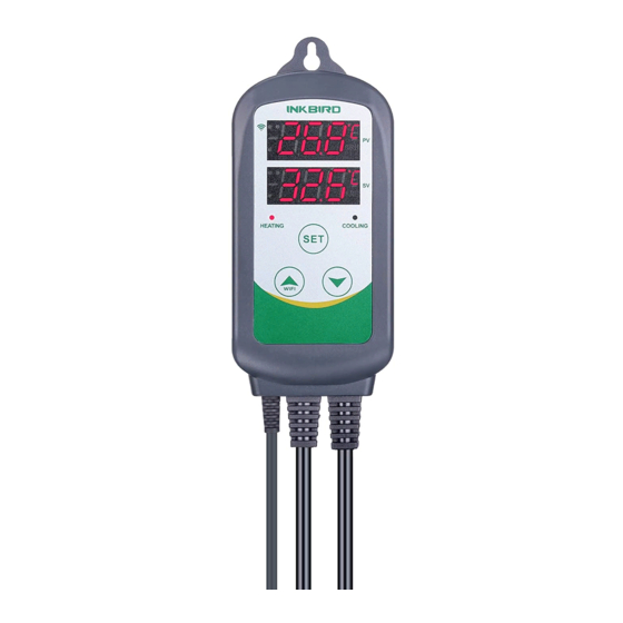
- Page 6 Get to Know the Device US S ocke ts E U S ocke ts UK S o ckets WIFI A U S o ckets PV: In normal mode, it displays current temperature; in settings mode, it displays menu code. SV: In normal mode, it displays the temperature setting value;...
- Page 7 COOLING: Cooling output socket. Setting button(SET),Increase button ( ),Decrease button( ): More WIFI details on Control Function Instructions. Inkbird Smart APP Setting 5.1 Download the APP Search the keyword “InkbirdSmart” in Appstore or Google Play, or scan the following QR code to download and install the APP.
- Page 8 “Add Home”button to create your home. Tap “+” or “add device” button in home page of the APP to add the device. If the controller is in the normal working state, you can long press WIFI seconds to reset the WIFI. It will enter the Smartconfig configuration state by default.
- Page 9 Add device in quick connection: ● Plug the device in the socket and make sure that the device is in the Smartconfig. ● configuration state (the LED symbol is flashing, interval flashing 250ms). Click “Confirm indicator rapidly blink” and then select Wi-Fi network, enter Wi-Fi password,click “confirm”...
- Page 10 Add device in AP mode: ● Plug the device in the socket and make sure that the device is in the AP Configuration State (the LED symbol is flashing slowly, interval flashing 1500ms). ● Click “ ” to enter device adding WIFI interface,click “Confirm indicator slowly blink”...
- Page 11 Click “Done” after adding device succeedfully and enter into device controlling interface . In the temperature control mode, user can set control function via APP.
- Page 12 Device Name Device Information Back to Home Page PV:Current Temperature Control Mode SV:Temperature Setting Value Temperature Trend Diagram Menu Setting Back to Front Page Heating Difference Value Cooling Difference Value High Temperature Alarm Low Temperature Alarm Refrigeration Delay Temperature Calibration Temperature unit switch℃/℉...
- Page 13 Control Function Instructions 6.1 Button Operation Instructions 6.1.1 Button Function in Normal Operation Mode 6.1.1.1 Quickly press " ", PV shows HD, SV shows heating difference value; Short Press " " again, PV shows CD, cooling difference value. And It will be back to the normal display if there is no operation for 3 seconds or pressing the SET button.
- Page 14 6.1.2 Button Function in Setting Mode When the controller is working normally, press the SET button for 2 seconds to enter the setting mode. The PV digital tube shows the first menu code“TS”, SV shows the corresponding setting value. Press SET button to scroll down the menu item and save the parameters of the previous menu item.
- Page 15 6.2 Menu Setting Flow Chart Press "SET" Key for over 2 seconds to enter parameters setting mode 77.0℉ Temperature Set Value 3.0℉ Heating differential value 3.0℉ Cooling difference value 212℉ Alarm High Limit -40.0℉ Alarm Low Limit OMinute Compressor Delay Time 0.0℉...
- Page 16 6.3 Setting Menu Instruction Default Code Symbol Function Setting Range Annotation Settings Temperature Setting -40.0°C~100°C 25.0°C Value -40.0°F~212°F 77.0°F Heating Difference 0.3°C~15.0°C 2.0°C More details on 6.4.1 Value 1.0°F~30.0°F 3.0°F Cooling Difference 2.0°C 0.3°C~15.0°C Value 1.0°F~30.0°F 3.0°F Alarm High -40.0°C~100°C 100°C Temperature Limit -40.0°F~212°F...
- Page 17 6.4.1.1 Normal Temperature Control When the measured temperature PV ≤ TS (Temperature Setting Value) – HD (Heating difference value),the controller will enter the heating state, the red led is on, HEATING output works. When the measured temperature PV ≥ TS(Temperature Settin Value), the red led is off and the HEATING output turns off.
- Page 18 measured temperature value 27.0°C(TS+CD), the controller enter the cooling state; when measured temperature value ≤25.0°C, cooling will stop. 6.4.1.2 Special Temperature Control If there is no need to judge the return difference in heating or cooling when power on or exiting the setting state, then it directly compare with TS.
- Page 19 6.4.2 Alarm High / Low Temperature Limit Settings (AH,AL) When measured temperature ≥AH (high temperature limit alarm), hen it will turn off heating or cooling output, AH flashes alternately with the current temperature, meantime buzzer will“bi-bi-Biii”alarm, until the temperature <AH, buzzer off and return to normal display and control.
- Page 20 is turned on for the first time, PV(mea- sured temperature value) ≥ TS(Tempera- ture setting value) + CD(Cooling difference value), it will not start cooling immediately, but waiting for a delay time(PT). When two adjacent of cooling starting intervals are greater than the delay time, it will immedi- ately start cooling;...
- Page 21 6.4.5 Fahrenheit or Celsius Settings (CF) User can set the display unit to Fahrenheit or Celsius according to their habits. The default temperature is Fahrenheit. If you need to display the unit in Celsius, then set the CF to C. Please note that when the CF changes state, all setting values are restored to the default setting and the buzzer gives a short beeping prompt.
- Page 22 Saturday. You can also visit our web site www.ink-bird.com to find the answers of the common technical questions. 8.2 Warranty INKBIRD TECH. C.L. warrant this controller for two years(temperature sensor for one year) from the date of purchase when operated under normal...
- Page 23 (not transferable), against defects caused by INKBIRD’s work manship or materials. This warranty is limited to the repair or replacement, at INKBIRD’s discretion, of all or part of the controller. The original receipt is required for warranty purposes.
Need help?
Do you have a question about the ITC-308-WIFI and is the answer not in the manual?
Questions and answers
My new ITC-308 thermostat will not register. After going through the connection phase it says “device not responding “ retried several times.