
Related Manuals for Vaillant multiMATIC VRC 700f/4


Summary of Contents for Vaillant multiMATIC VRC 700f/4
- Page 1 Operating instructions multiMATIC VRC 700f/4 AT, BE (de), CH (de), DE Publisher/manufacturer Vaillant GmbH Berghauser Str. 40 D-42859 Remscheid Tel. +49 21 91 18‑0 Fax +49 21 91 18‑2810 info@vaillant.de www.vaillant.de...
-
Page 2: Table Of Contents
Contents Contents Troubleshooting ..........27 Maintenance messages ........28 Index ................... 29 Safety ..............3 Action-related warnings ......... 3 Intended use ............3 General safety information ........3 Notes on the documentation ......5 Observing other applicable documents ....5 Storing documents.......... -
Page 3: Safety 1
Safety 1 not be carried out by children unless they are Safety supervised. Action-related warnings Any other use that is not specified in these in- Classification of action-related warnings structions, or use beyond that specified in this The action-related warnings are classified in document shall be considered improper use. - Page 4 1 Safety ▶ If you cannot ensure the operation, have a competent person drain the heating install- ation. Operating instructions multiMATIC 0020237615_02...
-
Page 5: Notes On The Documentation
Notes on the documentation 2 Notes on the documentation Product description Observing other applicable documents Design of the product ▶ 3.1.1 Radio receiver unit You must observe all operating instructions enclosed with the system components. Storing documents ▶ Keep this manual and all other applicable documents safe for future use. -
Page 6: Main Function
3 Product description 3.1.3 Radio outside temperature sensor 3.2.4 Domestic hot water generation A temperature sensor measures the temperature of the wa- ter in the domestic hot water cylinder and forwards the val- ues to the system control. If the temperature lies below the set value, the system control increases the temperature in the domestic hot water circuit and therefore heats up the wa- ter to the set domestic hot water temperature. -
Page 7: Avoiding Moisture And Mould Damage
Current selection level with Directive 2014/53/EU. The complete text for the EU De- Setting level claration of Conformity is available at: http://www.vaillant- Values group.com/doc/doc-radio-equipment-directive/. In the setting level, you can select the values you want to read or change. -
Page 8: Basic Display
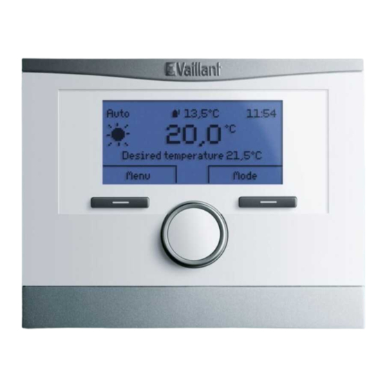
4 Operation the basic display and the mode that this operating mode is The system control must retrieve the values from the radio receiver unit first, which can take up to 2 seconds. During that time, the display shows dashes (--) instead of values. 4.2.3.1 Basic display for the Heating operating 4.1.5 Soft key function for the selection buttons... - Page 9 Operation 4 – 4.3.1.2 Desired temperature in the Cooling Navigate through the list entries for a selection level. – operating mode Select a selection level or setting level. – Change a selected set value. Mode Time Effect The display shows an element that is highlighted by white periods writing on a black background.
-
Page 10: Operating And Display Functions
5 Operating and display functions ◁ 4.3.2 Example, changing the display contrast The system control switches to setting level Display. The adjustable value for the Display contrast is highlighted. Auto 15:34 5.0 °C 19.5 Display °C Display contrast Button lock Desired heating temp. -
Page 11: Information
Operating and display functions 5 Menu → Information → System status → Curr. room air Information hum. 5.1.1 Reading the system status – You can use this function to read the current room air Menu → Information → System status humidity. - Page 12 5 Operating and display functions Menu → Information → Consumption → Last month → The system control has an integrated temperature sensor, Heating → Electricity which determines the room temperature. – You can use this function to read the total electrical con- 5.1.1.3 Ventilation sumption for heating in the last month.
-
Page 13: Settings
Operating and display functions 5 5.1.2.4 Diagram: Reading the electrical 5.2.1.2 Hot water generation consumption Danger! Menu → Information → Electrical consumption Risk of death from legionella. – The diagram under Electrical consumption shows a Legionella multiply at temperatures below comparison between the monthly consumption of electri- 60 °C. - Page 14 5 Operating and display functions 5.2.3.1 Heating operating mode example: Time period for a day Individual dates vary from the selected time programme Mo-Su. 21 °C Back If you press the right-hand selection button Select, a mes- sage appears on the display which informs you about differ- 16 °C ent time periods.
- Page 15 Operating and display functions 5 5.2.3.8 Setting the Ventilation time programme 5.2.6.1 Setting your language Menu → Time programmes → Ventilation Press the left-hand selection button repeatedly until the basic display appears. – The time programmes are only effective for ventilation Press the left-hand selection button again.
- Page 16 5 Operating and display functions rotary knob, the button lock is active and you can no 5.2.12.2 Setting the low-tariff electricity rate longer change any functions unintentionally. Menu → Basic settings → Costs → Low-tariff elec. rate Each time you actuate the system control, the following mes- –...
-
Page 17: Operating Modes
Operating and display functions 5 5.2.18 Resetting to default setting Auto: The operating mode brings the zone to the desired temperature set for Day temp. heating in the time periods You can reset the settings for the Time programmes or for that you have set in the time programme. -
Page 18: Advanced Functions
5 Operating and display functions 5.4.2 Activating 1 day at home Day: The operating mode constantly controls the exchange of air using the value that you set in the Max. vent. stage: Op. mode → 1 day at home Day ventilation level. Menu →... -
Page 19: Messages
Troubleshooting 6 Troubleshooting 5.4.6 Activating Cylinder boost Op. mode → Cylinder boost Overview of fault messages (→ Appendix B) – The Cylinder boost advanced function heats the water in the domestic hot water cylinder until it reaches the set Implementing the setting if the heat pump desired temperature Domestic hot water. -
Page 20: Care
7 Care Remove the system control from the unit mounting Clip the system control into the unit mounting bracket bracket as shown in the figure. as shown in the figure, making sure that it clicks into place. Care Caring for the product ▶... -
Page 21: Guarantee And Customer Service 9
Kundendienst ausgeführt. Wir können Ihnen daher etwaige Kosten, die Ihnen bei der Durchführung von Arbeiten an dem Die N.V. VAILLANT gewährleistet eine Garantie von 2 Jah- Gerät während der Garantiezeit entstehen, nur dann erstat- ren auf alle Material- und Konstruktionsfehler ihrer Produkte ten, falls wir Ihnen einen entsprechenden Auftrag erteilt ha- ab dem Rechnungsdatum. -
Page 22: 10 Technical Data
10 Technical data 10 Technical data 10.1 Product data in accordance with EU Ordinance no. 811/2013, 812/2013 On units with integrated weather compensators, including a room thermostat function that can be activated, the seasonal room-heating efficiency always includes the correction factor for controller technology class VI. -
Page 23: Appendix
Appendix Appendix Overview of the operating and display functions Note The functions and operating modes listed are not available for all system configurations. Operating modes Operating mode Setting Default setting Operating mode Heating off, Auto, Day, Set-back Auto Cooling off, Auto, Day Auto Ventilation Auto, Day, Set-back... - Page 24 Appendix Setting level Values Unit Increment, select Default setting Min. Max. Air quality sensor 1 Current value Air quality sensor 2 Current value Exhaust air humidity Current value %rel Information → Consumption → Current month → Heating ---- Electricity Total value for the current month Fuel Total value for the...
- Page 25 Appendix Setting level Values Unit Increment, select Default setting Min. Max. Bar chart Previous year to cur- kWh/month rent year comparison Information → Heat recovery → Bar chart Previous year to cur- kWh/month rent year comparison Information → Contact details → Installer Phone number Current values Information →...
- Page 26 Appendix Setting level Values Unit Increment, select Default setting Min. Max. Mon – Sun: 00:00- Individual days and blocks Monday, Tuesday, Wednes- day, Thursday, Friday, Sat- 00:00 urday, Sunday and Monday - Friday, Saturday - Sunday, Monday - Sunday Period 1: Start – End 00:00 24:00 h:min...
-
Page 27: Contents B Troubleshooting
Appendix Setting level Values Unit Increment, select Default setting Min. Max. Cooling off, Auto, Day Auto 1 day at home Active, Not active Not active 1 day away from home Active, Not active Not active Ventilation boost Active, Not active Not active Party function Active, Not active... -
Page 28: C Maintenance Messages
Appendix Symptom Possible cause Measure Display view: Fault F. Fault: Heat generator faults Carry out a Reset fault message (→ Page 19). Heat generator 1, the specific If the fault persists, inform the competent person. fault code (e.g. F.33) and the specific heat generator appear behind F. -
Page 29: Index
Index Index Intended use................3 Language selection ............. 15 1 day at home ..............18 Main function ................. 6 1 day away from home............18 Maintenance message ............19 Manual cooling ..............18 Activating Button lock ............15 Activating Heat recovery ............ 16 Nomenclature ................ - Page 30 Index System OFF ................ 19 System status..............11 Time period, deviating times in the block ......14 Time programme ............... 13 quick setting..............14 Setting................14 Ventilation................6 Ventilation boost ............... 18 Ventilation level ..............13 Zone ................6, 13 Zone in the basic display............
- Page 32 0020237615_02 0020237615_02 11.01.2018 Supplier Vaillant Deutschland GmbH & Co.KG Berghauser Str. 40 D-42859 Remscheid Telefon 021 91 18‑0 Telefax 021 91 18‑2810 Auftragsannahme Vaillant Kundendienst 021 91 5767901 info@vaillant.de www.vaillant.de Vaillant Group Austria GmbH Clemens-Holzmeister-Straße 6 1100 Wien Telefon 05 7050 Telefax 05 7050‑1199 Telefon 05 7050‑2100 (zum Regionaltarif österreichweit, bei Anrufen aus dem Mobilfunknetz ggf. abweichende Tarife - nähere Information erhalten Sie bei Ihrem Mobilnetzbetreiber)
Need help?
Do you have a question about the multiMATIC VRC 700f/4 and is the answer not in the manual?
Questions and answers