
Subscribe to Our Youtube Channel
Related Manuals for Vaillant VRC 430


Summary of Contents for Vaillant VRC 430
- Page 1 For the operator/for the heating engineer Operating and Installation Manual VRC 430 Weather compensator VRC 430...
-
Page 3: Table Of Contents
For the operator Operating Manual VRC 430 Weather compensator VRC 430 Contents Appliance features .............4 Operating concept ..........8 Application ................4 4.3.1 Show various display screens ......9 Product features ..............4 4.3.2 Changing parameters..........9 4.3.3 Operation in the simplified basic display ..11 Notes on the documentation ...... -
Page 4: Appliance Features
The room temperature is based only on your preset values. The system compensates for the effect of the The VRC 430 can form part of a new heating and hot external temperature. water generation unit or can also be retro-fitted into an existing installation. -
Page 5: Notes On The Documentation 1
Safety Glossary: At the end of this document, in the appendix, you will The VRC 430 may only be installed by a suitably quali- find an explanation of technical terms and important fied expert technician. This engineer also assumes re- functions listed in alphabetical order. -
Page 6: Notes On Operation
– the unit is not blocked by furniture or other obstacles. – the radiator valves in the room in which the VRC 430 is fitted are fully open. "room temperature compensation" means that the... -
Page 7: Operation 4
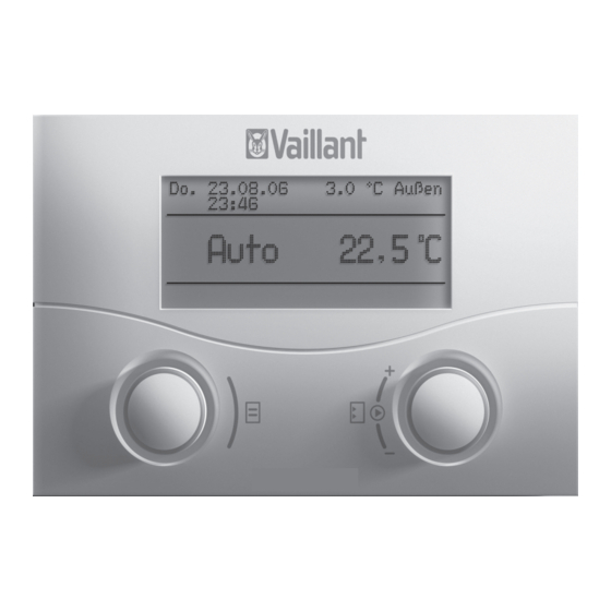
– the operating mode (automatic, manual or off) of the heating circuit 1 – the current internal temperature The default display is described in detail in Chapter 4.3.3. The functions of the two dials are described in Chapter 4.3. Operating Manual VRC 430 0020042468_02... -
Page 8: Overview Of The Display (Display Field)
The two dials (Fig. 4.1 Items 2 and 3) function according in the operator level (see Chapter 4.4 and 4.5) to the Vaillant "turn and click" principle. – Display/input screens for operating and installation- When the dials are turned (forwards or backwards) you specific parameters at installer level can hear them click into position. -
Page 9: Show Various Display Screens
Auto Time programme > Select target hot water 06 : 00 - 10 : 40 21.5 °C Fig. 4.5 Jump to the various modifiable parameters > Select day of week Fig. 4.4 Displaying various screens Operating Manual VRC 430 0020042468_02... - Page 10 > Select room temperature Fig. 4.7 Changing a parameter value ⇒ Press the right-hand dial. The displayed value is confirmed and accepted for the control system. The value display changes from high- lighted to normal. Operating Manual VRC 430 0020042468_02...
- Page 11 VR 61 (for a second heating programme and other parameters circuit) is not connected and the VRC 430 is such as set-back temperature and wall-mounted (not on the front of the heating heating curve.
-
Page 12: The Period Of Validity For New Control System Target Values
Fig. 4.11. For this to happen the selected heating curve must correspond to the conditions and the room tempera- ture control function must be activated. Operating Manual VRC 430 0020042468_02... -
Page 13: Operator Level, Expert Technician Level
If additional components are installed and controlled by this period (4). the VRC 430, the display screens listed in table 4.4 will After this period, the control system reverts to the set- contain the additional screens as required, e.g. 3 or back temperature (15 °C). - Page 14 This relationship is repre- sented in heating curves. You can select from a va- riety of heating curves (see Chapter 4.7.3). Table 4.4 Screens in the operating level for the operator Operating Manual VRC 430 0020042468_02...
-
Page 15: Changing The Displays (Examples)
Select the start time by rotating the right-hand dial. Fig. 4.13 Screen 2 (example) The time jumps in ten-minute increments for every turn (click) of the dial. ⇒ When the start time is displayed, confirm by clicking the right-hand dial. Operating Manual VRC 430 0020042468_02... -
Page 16: Programming Holiday Periods
Set the end date for the holiday period in the same way. Enter the target room temperature as follows: ⇒ Turn the right-hand dial until the cursor is in front of the input field for the target room temperature. Operating Manual VRC 430 0020042468_02... -
Page 17: Entering Parameters For The Heating Circuit
Fig. 4.15 Diagram with heating curves for a target room tem- The display field shows the text "set heating curve" in perature of 20 °C the comment field. ⇒ Press the right-hand dial. Operating Manual VRC 430 0020042468_02... -
Page 18: Entering Parameters For Hot Water Generation
Select the target temperature so that nobody is in danger. 4.7.5 Renaming the heating components Screen 14 indicates which components you can re- name. Change names Bathroom 1 > Select Fig. 4.17 Screen 14 (example) Operating Manual VRC 430 0020042468_02... -
Page 19: Status And Error Messages 5
Draws attention to a fault in the heating unit. ⇒ Contact your expert technician. The unit is faulty if the screen remains dark or you are unable to make any changes using the dial. ⇒ Contact your expert technician. Operating Manual VRC 430 0020042468_02... -
Page 21: Installation Manual
For the heating engineer: Installation Manual VRC 430 Weather compensator VRC 430 Contents Notes on the documentation ......2 Installation ............7 Storing of the documents ........2 Electrical installation of the controller Symbols used ............2 when mounted on the wall ........7 Applicability of the manual ........2... -
Page 22: Notes On The Documentation
The part number of your unit can be obtained from the identification plate. Other applicable documents – The operating instructions for the Vaillant controller VRC 430 (Section 1 of this document) – The operating and installation instructions for your heating unit –... -
Page 23: Description Of The Appliance 2
The VRC 430 is a weather compensator designed for heating and hot water generation in conjunction with a Vaillant boiler (eBUS-capable). The VRC 430 can also be used to control the following accessory components: – Circulation pump for hot water generation in conjunc- tion with a multi-functional module 2 of 7 –... -
Page 24: Intended Use
The VRC 430 controller is designed for use as a weather compensator and timer-based controller with or without Safety information hot water generation/ circulation pump in conjunction with a Vaillant heating unit with eBUS interface. -
Page 25: Assembly 4
Carefully press the controller (without wall plinth, Solar module VR 68 see Fig. 4.1) with the pin rail into the plug connector The solar module VR 68 can be used by the VRC 430 to on the heating unit. ⇒... -
Page 26: Wall Mounting The Controller
(5) on the wall socket. Fig. 4.2 Fitting the external sensor VRC 693 Casing cover 2 Wall plinth 3 Cap nut for cable conduit 4 Connection cable with drip loop 5 Installation opening Installation Instructions VRC 430 0020042468_02... -
Page 27: Installation 5
Do not forget the seal between the wall socket and the cover for the enclosure. Fig. 5.1 Electrical connection with VRC 430 Terminal rail VRC 430 2 Heating unit terminal rail Installation Instructions VRC430 0020042468_02... -
Page 28: Electrical Installation Of Theexternal Sensor Vrc 693
Connect the 6-pole edge connector to plug location X41 on the heating unit. Proceed as follows: Electrical installation of the external sensor ⇒ Connect the eBUS cable to the VRC 430 terminal VRC 9535 rail. The power supply to the heating unit is switched off and ⇒... -
Page 29: Initial Start-Up 6
This ensures optimum control system by the To exit the installation assistant: VRT 430. ⇒ Turn the left-hand dial clockwise to access screen The VRC 430 operating concept is described in the op- ⇒ erating instructions in Chapter 4.3. Click "Yes" to exit. Installation assistant... -
Page 30: Restoring Default Parameters
You can change the code on screen C24. After entering the correct code you automatically ac- cess screen C1 on the expert technician level. Restoring default parameters You can restore the VRC 430 default settings as fol- lows: ⇒ Simultaneously press and hold both dials for... - Page 31 Initial start-up 6 Dis- Title display adjustable operat- Remarks Unit Min. Max. Step width Preset play screen ing values value value value screen (only display = A) Supply target (A) Flow temperature tar- °C Information get value Pump status (A) On, Off FBG connection/ Remote control con-...
- Page 32 Matching of the exter- ture correction nal sensor Correction room ac- Matching the room tual value temperature sensor Display contrast Software versions Software version Version number display per module (A) Table 6.2 Screen in expert technician level (continued) Installation Instructions VRC 430 0020042468_02...
-
Page 33: Grout Drying Function
When the function is started, the current time of the start is saved. The day is changed exactly at this time. Handing over the appliance to the owner The owner of the VRC 430 must told how to use and op- erate the controller. ⇒... -
Page 34: Recycling And Disposal
Both your VRC 430 and its packaging are primarily made of recyclable raw materials. Appliance Neither the VRC 430 nor any of its accessories may be disposed of in the household waste. Make sure the old appliance and any accessories are disposed of properly. -
Page 35: Glossary
Appendix Glossary Glossary The frost protection function monitors the external tem- perature. If the outside temperature drops below 3 °C, Set-back temperature the heating pump switches on for 10 minutes and then The set-back temperature is the temperature to which off for 10 to 60 min (depends on the outside tempera- your heating lowers the internal temperature to outside ture). - Page 36 In the screen C8 "HC1 Parameter", in the menu point "Room control" you can decide whether to use the tem- perature sensor fitted in the VRC 430 or in the remote control unit. To do this the VRC 430 must be wall- mounted and the remote control unit VR 81 must be connected.
- Page 37 (Selection: Auto). The default setting is switches off automatic changeo- ver (Selection: Off). If the VRC 430 is equipped with the external sensor VRC 9535 which receives the DCF77 time signal, sum- mer/winter changeover takes place automatically; in this case there is no way to switch off the automatic changeover option (Selection: Off).
Need help?
Do you have a question about the VRC 430 and is the answer not in the manual?
Questions and answers