Table of Contents
Advertisement
Quick Links
Advertisement
Table of Contents

Subscribe to Our Youtube Channel
Related Manuals for Vaillant VR 51


Summary of Contents for Vaillant VR 51
- Page 1 Room thermostat VR 51 Operating and installation instructions...
-
Page 2: Table Of Contents
Contents Safety ..............4 1.1 Action-related warnings ......... 4 1.2 Intended use ............5 1.3 General safety information ........6 Notes on the documentation ......8 2.1 Observing other applicable documents....8 2.2 Storing documents ..........8 2.3 Validity of the instructions ........8 System and product description ....... - Page 3 Troubleshooting ..........29 7.1 Detecting and rectifying faults ......29 7.2 Command not confirmed ........30 7.3 Resetting to factory setting ......... 30 Care and maintenance ........32 8.1 Caring for the product ......... 32 8.2 Changing batteries ..........33 Decommissioning ..........
-
Page 4: Safety
Safety Action-related warnings Classification of action-related warnings The action-related warnings are classified in accordance with the severity of the pos- sible danger using the following warning signs and signal words: Warning symbols and signal words Danger! Imminent danger to life or risk of severe personal injury Danger! Risk of death from electric shock... -
Page 5: Intended Use
Intended use In the event of inappropriate or improper use, damage to the product and other property may arise. You can use the room thermostat for the time-controlled regulation of individual rooms. Intended use includes the following: – observance of accompanying operating, installation and servicing instructions for the product and any other system com- ponents... -
Page 6: General Safety Information
industrial use is also deemed to be improper. Caution. Improper use of any kind is prohibited. General safety information 1.3.1 Danger caused by improper operation Improper operation may present a danger to you and others, and cause material damage. > Carefully read the enclosed instructions and all other applicable documents, par- ticularly the “Safety”... - Page 7 1.3.3 Danger caused by a malfunction > Install the product such that room air can circulate freely around the product, and it is not covered by furniture, cur- tains or other objects. 1.3.4 Risk of material damage caused by unsuitable environmental conditions The electronics may be damaged if you install the product in an unsuitable environ-...
-
Page 8: Notes On The Documentation
Storing documents > Keep this manual and all other applica- ble documents safe for future use. Validity of the instructions These instructions apply only to: Product article number VR 51 0020247923 Operating and installation instructions 0020248975_02... -
Page 9: System And Product Description
System and product description Component of the ambiSENSE system The product is part of the ambiSENSE room climate solution and communicates via a radio protocol. All products in the ambiSENSE room climate solution can be configured via the app using a smartphone. You can use the room thermostat with air- humidity sensor for the time-controlled reg- ulation of the room temperature via the app... -
Page 10: Design Of The Product
The installation takes place by screwing in or sticking the mounting plate and fasten- ing in the clip-on frame that is supplied. The product can be integrated into existing switch series. Design of the product 1 Mounting plate 2 Clip-on frame 3 Setting wheel 4 System button 5 Display... -
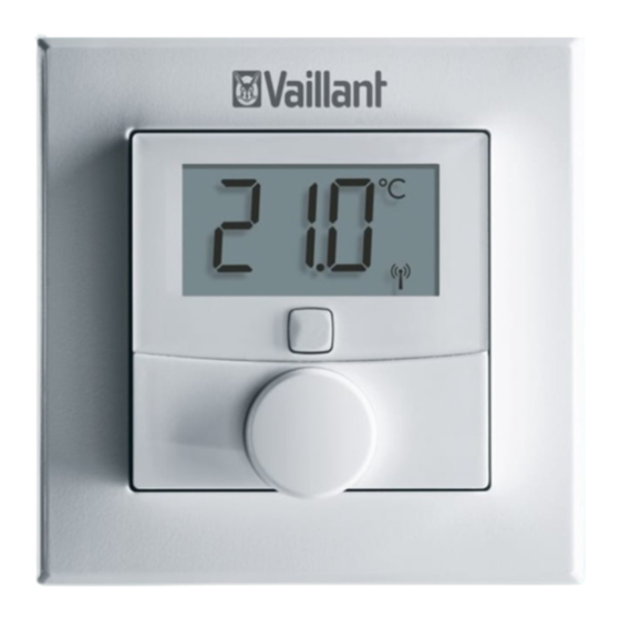
Page 11: Display
Display Note The background lighting for the display is switched off in standby mode. To activate the background lighting, press the setting wheel once. MANU BOOST 1 Operation lock active 2 Unit for the numeric display 3 Automatic decrease active 4 Radio data transmission Operating and installation instructions 0020248975_02... -
Page 12: Radio Operation
5 Low battery charge 6 Boost mode active 7 Manual mode active 8 Target/actual temperature 9 Setting mode active Radio operation The radio signal is transmitted on a non- exclusive transmission path. Faults can therefore not be ruled out. Interferences may, for example, be caused by switching operations, electric motors or defective electrical units. -
Page 13: Flashing Sequence Of The Signal Led
Flashing sequence of the signal LED Flashing Required Meaning sequence activity Brief period Radio trans- Wait until the of flashing mission/ transmission orange transmission has ended. attempt or configuration data is trans- ferred 1 x long Process con- Continue with period of firmed the operation. - Page 14 Flashing Required Meaning sequence activity Brief period Batteries flat Replace the of lighting up batteries. orange (after a green or red reception notification) 3 x long Product Note the dis- period of defective play in your flashing red App or con- tact your spe- cialist dealer.
-
Page 15: Duty Cycle Limit
Flashing Required Meaning sequence activity Long and Update to the New software brief period of unit software is transferred. flashing (OTAU = (Duration: Up orange Over the Air to 12 hours) (alternating) Update) This does not affect how the product works during this time. -
Page 16: Ce Marking
during start-up or the new installation of a system, increased and radio-intensive pair- ing processes may mean that this limit is not reached. If the duty cycle limit is exceeded, the signal LED lights up red for one extended period and may indicate that a function is temporarily missing from the product. -
Page 17: Checking The Scope Of Delivery
Checking the scope of delivery > Check that the scope of delivery is com- plete and intact. Number Designation Room thermostat Clip-on frame Mounting plate 1.5 V LR03/Micro/AAA batteries 5 mm rawl plug, 3 x 30 mm cross-head screws... -
Page 18: Integration Into The Ambisense System
Integration into the ambiSENSE system Pairing To ensure that the room thermostat is inte- grated into the ambiSENSE system and can communicate with other ambiSENSE units, it must first be paired to the gateway. You should therefore first set up the gate- way via the app in order to be able to use ambiSENSE units in the system. - Page 19 and pull the insulating strips out of the battery compartment. > When you are prompted to do so by the installation assistant for the app, enter the digits of the unit number (SGTIN = Serialised Global Trade Item Number) in the app to confirm or use the smart- phone to scan the QR code.
-
Page 20: Set-Up
Set-up Defining the installation site Install the room thermostat: – On an interior wall of the living room Height: ≈ 1.5 m above the floor In a frost-free room Do not install the room thermostat: – Close to heat sources, such as radia- tors, chimney walls, television sets, direct sunlight –... - Page 21 you can integrate it into an existing switch series. To install it in the clip-on frame, you can use either the supplied double-sided adhe- sive strips or the supplied screws to secure the room thermostat to the wall. Installation with double-sided adhe- sive strips >...
- Page 22 > Secure the adhesive strips (1) to the rear of the mounting plate (2) in the markings provided for that purpose. Ensure that you can read the writing on Operating and installation instructions 0020248975_02...
- Page 23 the rear and that the clips for the mount- ing plate can click into the openings on the room thermostat. > Remove the plastic film from the adhe- sive strips. > Press the assembled room thermostat onto the wall with the rear at the required position.
- Page 24 Screw mounting > Select a suitable installation site in the room. Note Ensure that no cables or pipes are routed within the wall. Operating and installation instructions 0020248975_02...
- Page 25 > Use the mounting plate to mark two of the drill holes located diagonally oppo- site to each other. Note Ensure that the arrow on the front of the mounting plate is pointing upwards. > If required, use the holes (2) for the installation on a flush-mounted box.
- Page 26 you can integrate it into a multiframe. The room thermostat fits into frames from the following manufacturers: – Berker: S.1, B.1, B.3, B.7 glass – ELSO: Joy – GIRA: System 55, Standard 55, E2, E22, Event, Esprit – merten: 1-M, Atelier-M, M-Smart, M-Arc, M-Star, M-Plan –...
-
Page 27: Operation
Operation Changing the operating mode Automatic mode: The heating programme that is set via the app is active. Manual mode: You can set the temperature on the product or by using the app. The tempera- ture setting is retained until the next time a manual change is implemented. -
Page 28: Using The Boost Function
ally set temperature should apply can be individually defined here. In manual mode, the temperature is retained until the next time a manual change is implemented. > Turn the setting wheel clockwise or anti-clockwise to manually increase or decrease the room temperature. –... -
Page 29: Troubleshooting
Troubleshooting Detecting and rectifying faults Conditions: The room temperature does not reach the set temperature > Check whether the radiator thermostats on the radiators in the room in which the product is installed have radio contact with the Internet gateway. >... -
Page 30: Command Not Confirmed
> Check that the batteries for the room thermostat have been correctly inserted in the battery compartment. Command not confirmed If at least one transceiver does not confirm a command, the signal LED lights up red once the incorrect transmission is com- pleted. - Page 31 2. Re-insert the batteries in accordance with the polarity markings and, at the same time, press and hold the system button for four seconds until the signal LED starts to rapidly flash in orange. 3. Release the system button. Operating and installation instructions 0020248975_02...
-
Page 32: Care And Maintenance
4. Press the system button again for four seconds until the signal LED lights up green. 5. Release the system button to complete the process of restoring the factory set- tings. – The product restarts. Care and maintenance Caring for the product Caution. -
Page 33: Changing Batteries
Changing batteries 1. Remove the product from the mounting plate. 2. Always change all the batteries (1) at the same time. – Battery type: LR03/Micro/AAA 3. Do not use rechargeable batteries. 4. Insert the batteries, making sure that the poles are the right way round. Operating and installation instructions 0020248975_02... - Page 34 Note After inserting the batteries, the product first runs through a selftest for approx. two seconds. Initialisa- tion then takes place. 5. After inserting the batteries, observe the flashing sequence of the signal LED. – Self-test successful: Signal LED lights up orange first and then green.
- Page 35 > Ensure that you use the correct battery type when replacing bat- teries. > Dispose of used batteries in accordance with the instructions in this manual. 8.2.2 Leaking batteries Danger! Risk of chemical burns caused by leaking batteries! If the product is not used for several weeks, the batteries may leak.
- Page 36 8.2.3 Batteries > Note the battery type, as described in these instructions; see section “Data plate”. > Remove and insert batteries as described in these instructions; see sec- tion “Changing the batteries”. > Do not recharge non-rechargeable bat- teries. > Remove rechargeable batteries from the product before charging them.
-
Page 37: Decommissioning
> Do not short-circuit the connection con- tacts in the product’s battery compart- ment. Decommissioning Decommissioning the product 1. Delete the product in the app. 2. Remove the product from the wall. 3. Remove the batteries. Recycling and disposal If the product is labelled with this mark: >... -
Page 38: 10 Customer Service
If the product contains batteries that are labelled with this mark, these batteries may contain substances that are hazard- ous to human health and the environment. > In this case, dispose of the batteries at a collection point for batteries. 10 Customer service The contact details for our customer ser- vice are provided on our website. - Page 39 Parameter Value Degree of contamination Maximum permitted 0 … 35 °C environmental temperature Height 86 mm (3.39 in) Width 86 mm (3.39 in) Depth 25 mm (0.98 in) Weight (incl. batteries) 100 g (3.53 oz) Transmission 868.0 - 868.6 MHz / frequency 869.4 - 869.65 MHz Maximum...
- Page 40 0020248975_02 Supplier Vaillant Ltd. Nottingham Road Belper Derbyshire DE56 1JT Telephone +44 330 100 3461 www.vaillant.co.uk info@vaillant.co.uk © These instructions, or parts thereof, are protected by copyright and may be reproduced or distributed only with the manufacturer's written consent. We reserve the right to make technical changes.
Need help?
Do you have a question about the VR 51 and is the answer not in the manual?
Questions and answers