
Related Manuals for Vaillant VRC 430


Summary of Contents for Vaillant VRC 430
- Page 1 For the heating engineer/for the owner Operating and Installation Manual VRC 430 Weather compensator VRC 430...
-
Page 3: Table Of Contents
For the owner Operating instructions VRC 430 Weather compensator VRC 430 Contents 4.3.3 Operation in the default display ......11 Changing the target room temperature ...12 User level, level for the installer ......13 Equipment properties ..........4 Screens in the user level ........13 Application ................4 User screens (examples) ........ -
Page 4: Equipment Properties
Product specifications – eBUS interface – Data connection with a Vaillant boiler via an eBUS line – Illuminated graphical display (display field) – Operation via both dials in accordance with the principle "Turn and Click"... -
Page 5: Notes On The Documentation
The part number of your unit can be obtained by asking your installer. Other applicable documents – The installation instructions for the Vaillant controller CE label VRC 430 (Section 2 of this document, for the heating The CE mark documents the fact that the controller... -
Page 6: Instructions For Operation
– Second heating circuit using the Vaillant Mixer (0870 6060 777) for further details. Module VR 61 – Solar system using the Vaillant Solar Module VR 68 Vaillant warranty – VR 81 remote room temperature control device We only grant a Vaillant manufacturers warranty if a –... -
Page 7: Operation 4
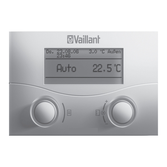
Operation 4 Operation Note! The operation of the VRC 430 should be explained to you after installation by the installer. This will prevent involuntary changes to the settings. Overview operating and display front Th. 12.01.06 3.0 °C Outside 11:46 19.0 °C Auto VRC 430 Fig. -
Page 8: Overview Of The Displays
(see Chapter 4.4 and 4.5) The two dials (Fig. 4.1 Items 2 and 3) function according – Display/input screens for operating and installation to the Vaillant principle "Turn and Click". specific parameters in the installer level When turning the dials (clockwise or anti-clockwise), they index positively with each step. -
Page 9: Show Various Screens
Operation 4 4.3.1 Show various screens 4.3.2 Changing parameters By turning the left-hand dial you can page through the Turn the right-hand dial to scroll through the individual screens of the display like a book. parameters within the screen. Example: The position is indicated by the cursor (see Fig. - Page 10 4 Operation Click the right-hand dial. Turn the right-hand dial to show the possible values. The parameter value marked by the cursor is highlighted. Th. 12.01.06 Outside 3.0 °C 11:46 Auto 21.0 °C Th. 12.01.06 3.0 °C Outside 56.0 °C Auto 11:46 21.0 °C...
-
Page 11: Operation In The Default Display
Operation 4 Changing parameters in the basic display The duration for which the new value remains definitive depends upon the set operating mode; see also Chapter 4.4. Parameter Meaning Room target The heating is controlled according to temperature the target room temperature and 4.3.3 Operation in the default display according to the operating mode, see... -
Page 12: Changing The Target Room Temperature
4 Operation Changing the operating mode in the default display Turn the right-hand dial. Instead of the room temperature, the current set room Operating Meaning mode temperature is highlightedd. After a delay of 1 second Auto(matic) The control of the heating circuit takes place in you can select the new room temperature: accordance with the guideline of the target room temperature, the time programmes and other... -
Page 13: Screens In The User Level
Operation 4 Level for the user, level for the installer The controller VRC 430 has two levels for the display/ 25 ° entry. Each level has a series of screens in which the parameters can be displayed, adjusted or changed. –... - Page 14 4 Operation Screen Title adjustable Remarks Unit Min. Max. Step Preset screen operating values value value distance/ value (only display = A) Selection possibilities Basic data Date Select Day, Month Weekday and Year separately; Time of the day Select Hour and Minutes separately Summer/Winter changeover Auto, Off...
-
Page 15: User Screens (Examples)
Operation 4 Screen Title adjustable Remarks Unit Min. Max. Step Preset value screen operating values value value distance (only display = A) Hot water Hot water target °C parameters temperature Changing the Heating circuit 1 Any name having up He 1 name to 8 characters can be Hot water... -
Page 16: Programming Holiday Periods
4 Operation The end time for window 1 should be set similarly. 4.7.2 Programming holiday periods For a longer period of time when you are not at home, The comfort temperature for time window 1 is set as you can define a lower room temperature. This will save follows: heating energy. -
Page 17: Heating Settings
Operation 4 Enter the room temperature as follows: Turn the right-hand dial until the cursor is in front of the room temperature. The explanation text "Select room temperature" appears. Click the right-hand dial. The field is highlighted. Turn the right-hand dial to set the room temperature (values from 5 °C to 30 °C in half degree steps and frost protection function are possible). -
Page 18: Hot Water Settings
4 Operation Turn the right-hand dial until the desired value is Attention! displayed (values from 5 °C to 30 °C in half degree Risk of being scalded by hot water! steps are possible). When the target temperature is above 60°C, Click the right-hand dial. -
Page 19: Status And Error Messages 5
Status and error messages 5 Status and error messages Status and error messages are displayed in the second row of the field for basic data. Status messages – Holiday programme active Within a specified holiday time period the heating is limited to the room temperature specified for this period. - Page 20 Operating instructions VRC 430...
-
Page 21: Installation Instructions
For the heating engineer Installation instructions VRC 430 Weather compensator VRC 430 Contents Installation ............8 Electrical installation of the control when mounted on the wall ........8 Notes on the documentation ......2 Electrical installation of the outdoor sensor Storage of the documents ........2 VRC 693 ..............8 Symbols used ............2 Electrical installation of the outdoor sensor... -
Page 22: Notes On The Documentation
The part number of your equipment can be taken from the identification plate. Other applicable documents – The operating instructions for the Vaillant controller VRC 430 (Section 2 of this document) – The operating and installation instructions for your heating installation –... -
Page 23: Description Of The Device 2
– Vaillant layer storage actoSTOR – Second heating circuit using the Vaillant Mixer Module VR 61 – Solar system using the Vaillant Solar Module VR 68 – Commercially available 230-V components (e.g. valves, cylinder thermostats) in combination with the Control... -
Page 24: Intended Use
– Second heating circuit using the Vaillant Mixer Module VR 61 Regulations During the electrical installation, observe the regulations – Solar system using the Vaillant Solar Module VR 68 – Commercially available 230-V components (e.g. valves, of your local power supplier. cylinder thermostats) in combination with the Control... -
Page 25: Assembly 4
Assembly 4 Assembly Relay box VR 41 Using the relay box VR 41, a 230-V cylinder thermostat The VRC 430 can either be plugged into the boiler fascia can be incorporated in the control system of the VR 430. or be installed in the living area on a wall. When mounting on the wall, the connection to the boiler is via VR 81 remote control device a twin-core eBUS line. -
Page 26: Mounting The Control On The Wall
4 Assembly This is how to do it: The electrical installation is carried out as described in Chapter 5.1. Switch off the boiler. Carefully push the controller onto the wall socket Turn off the power supply to the boiler and secure until it clicks in position. - Page 27 Assembly 4 This is how to do it: Mark the position on the wall. Observe the cable routing for the outside sensor. Route the connection cable (4) with a slight incline to the outside and with a drip loop. Remove the cover from the enclosure (1) of the outside sensor.
-
Page 28: Installation
5 Installation Installation This is how to do it: Connect the eBUS cable to the terminal rail of the Danger! VRC 430. Voltage carrying connections! Connect the eBUS cable to the terminal rail of the When working in the control cabinet of the boiler. -
Page 29: Electrical Installation Of The Outdoor Sensor Vrc 9535
Installation 5 Initial commissioning 6 Initial commissioning This is how to do it: Connect a 2-core cable to the terminals of the Initial condition: outside sensor in accordance with Fig. 4.2. The controller VRC 430 and the outside sensor are Connect the cable to the 6 pole edge connector correctly installed and connected. -
Page 30: Installer Level
6 Initial commissioning You can check operation of the boiler on screen A5: Code layer enabled Select the parameter value 50 °C for the parameter "activate boiler“. Check the reaction of the boiler. Code number 0 0 0 0 If you want to make any other changes: >... - Page 31 Initial commissioning 6 Title adjustable Remarks Unit Min. Max. Step Preset Screen screen operating values value value distance/ value (only display = A) Selection facility Target flow Flow temperature target °C Information temperature (A) value Pump status (A) On, Off Remote control Remote control connected? °C...
-
Page 32: Handing Over The System To The Owner
6 Initial commissioning Screen Title adjustable Remarks Unit Min. Max. Step Preset value screen operating values value value distance/ (only display = A) Selection facility Total system Mode Auto_OFF Determines the heating Frost Frost parameters control outside the protection, protection programmed time window ECO, set-back Frost protection = the... -
Page 33: Service, Warranty 7
(0870 6060 777) for further details. Level of protection IP 20 Protection class Vaillant warranty We only grant a Vaillant manufacturers warranty if a Maximum permissible ambient temperature 50 °C suitably qualified engineer has installed the system in Height mm accordance with Vaillant instructions. - Page 34 Appendix Glossary Glossary Frost protection function The frost protection system protects your heating Auto_Off (user level for the installer) system and your apartment from frost damage. It In the screen C21 "Entire system parameters" the control remains active in the operating mode "OFF". behaviour in the operating mode Automatic for the The frost protection function monitors the times in which no time windows are programmed can be...
-
Page 35: Glossary
Appendix Glossary It serves to display and to set/change the fundamental Feed temperature parameters. Setting/changing the parameters can be in ºC performed by the user without previous special knowledge and during normal operation. The heating system is continuously matched to the requirements of the user by corresponding adjustment of the fundamental parameters. - Page 36 Appendix Glossary Operating mode Target room temperature Operating modes "Auto" (Automatic), "Manual" and The target room temperature is the temperature that "OFF" are available. You can specify the way in which you would like in your apartment and which is specified your room heating and water heating are controlled in your controller.
Need help?
Do you have a question about the VRC 430 and is the answer not in the manual?
Questions and answers