Vaillant VRC 470 Instruction Manual
Hide thumbs
Also See for VRC 470:
- Installation insrtuctions (72 pages) ,
- Installation instructions manual (52 pages) ,
- Operating instructions manual (40 pages)

Related Manuals for Vaillant VRC 470


Summary of Contents for Vaillant VRC 470
- Page 1 Instructions for use For the operator Instructions for use VRC 470 Weather compensator GB, IE...
- Page 2 www.vaillant.de © Vaillant GmbH 2012 These instructions, or extracts thereof, may only be printed with the written consent of Vaillant GmbH. All designations of products in these instructions are brand names/trade marks of the companies in question. We reserve the right to make technical changes.
-
Page 3: Table Of Contents
Guarantee and customer service..... 22 Guarantee............22 Customer service..........22 Technical data............ 22 Controller ............. 22 Sensor resistances ..........22 Appendix ................23 Operating modes ..........23 Overview of operating levels ......23 Index ................... 29 0020116689_01 VRC 470 Instructions for use... -
Page 4: Notes On The Documentation
Applicability of the instructions These instructions apply for the following products only: VRC 470/3 and VRC 470/4 article number Great Britain 0020108130 Nomenclature The term "heat pump" is used if there is no difference between the heat pumps. -
Page 5: Safety
If you switch off the heating installation, parts of the heating installation may be damaged by frost. ▶ Do not disconnect the heat generator from the mains power. ▶ Leave the heating installation main switch in the "1" posi- tion. 0020116689_01 VRC 470 Instructions for use... -
Page 6: Ce Label
Even so, in the event of inappropriate or non-intended use, damage to the appliance and other property may arise. The controller controls a heating system with a Vaillant boiler with eBUS interface in a way that is weather-controlled and time-dependent. -
Page 7: Overview Of The Equipment 3
When the outside temperature is low, the control- ler increases the flow temperature of the Vaillant heating in- stallation. When the outside temperature rises, the controller reduces the flow temperature. Thus, the controller reacts to... -
Page 8: Frost Protection Function
The skilled tradesman will set further values for the heating installation via the access level for the skilled tradesman. The settings may only be made by someone with specialist knowledge; this level is therefore code-protected. Instructions for use VRC 470 0020116689_01... -
Page 9: Operating Concept
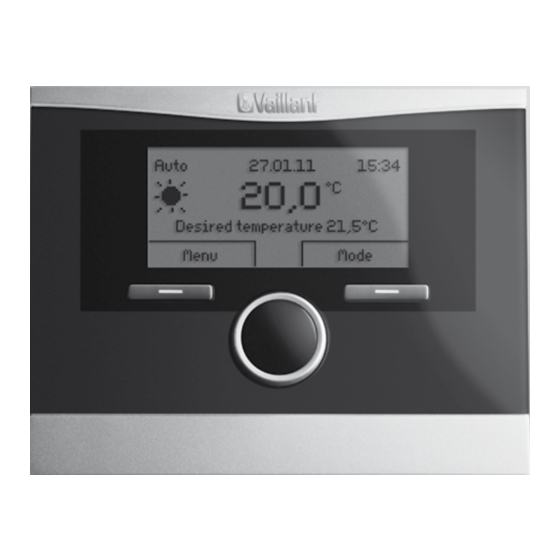
5 minutes, the basic display appears again. 4.2.1 Example: Operation in the basic display From the basic display, you can change the Desired day temperature directly for the current day by turning the rotary knob. 0020116689_01 VRC 470 Instructions for use... -
Page 10: Basic Settings
(to go back to the previous level), the right-hand the previous level), the right-hand selection button selection button has the function Select (to select has the function Change (the value). the highlighted menu option). Instructions for use VRC 470 0020116689_01... -
Page 11: Overview Of Setting And Read-Out Options
1. Menu → Information → System status → Solar yield – This function allows you to read the total solar yield. 0020116689_01 VRC 470 Instructions for use... - Page 12 Reading the current dew point – Serial number shows the serial number of the control- Menu → Information → System status → Current dew ler, which the competent person may require you to tell point Instructions for use VRC 470 0020116689_01...
-
Page 13: Settings
5.2.2 Setting the ventilation level heating circuit and hot water generation. Applies to: Controller version VRC 470/4 If a VR 61/4 mixer module is connected, HEATING 2 also appears under Desired temperatures. HEATING 2 has the Menu → Ventilation level same read-out options and settings as HEATING 1. - Page 14 5 Operating and display functions Applies to: Controller version VRC 470/4 If a ventilation unit is connected and ventilation is available, Individual dates vary from an additional list entry appears under Time programmes. the selected time programme Mo-Su. 5.2.3.2 Setting time periods for days and blocks...
- Page 15 5.2.3.11 For ventilation next time period. Set the time periods for hot water generation so that each Applies to: Controller version VRC 470/4 time period: Menu → Time programmes → Ventilation –...
- Page 16 Select this function to set the current date. All controller responds to 1 °C). K (Kelvin) is a unit for the temperature functions that contain a date relate to the set date. difference. Inputting a correction value affects the room tem- perature compensator. Instructions for use VRC 470 0020116689_01...
- Page 17 5 K, the cooling function is only activated once the outside temperature reaches 19 °C. 5.2.16 Activating heat recovery Applies to: Controller version VRC 470/4 5.2.15 Setting costs Menu → Basic settings → Heat recovery If the heat pump is connected and the competent person –...
-
Page 18: Operating Modes
Basic settings. In this case, you can set the operating mode separately for each heating circuit. The path details given at the start of each mode description indicate how you can access this mode in the menu struc- ture. Instructions for use VRC 470 0020116689_01... - Page 19 Outside the time period, hot water genera- 5.3.2 Operating modes for ventilation tion is switched off. Applies to: Controller version VRC 470/4 5.3.3.2 Comfort mode If a ventilation unit is connected, you can set the operating The comfort mode controls the hot water generation in ac-...
-
Page 20: Advanced Functions
Applies to: Controller version VRC 470/4 If the heating installation is equipped with two heating cir- cuits and both circuits are active, you can also activate an Ventilation is activated and works at the lowest ventilation advanced function using the left-hand selector button Menu. -
Page 21: Cylinder Boost
Low water pressure add-on module (monoblock heat function early. The heating installation will then return to the pump) pre-set mode. – Ventilation unit service (on VRC 470/4) 5.4.7 System OFF (Frost protection active) 5.5.2 Fault message Operating mode → System OFF... -
Page 22: Cleaning/Troubleshooting
Cleaning the controller Guarantee Clean the casing of the controller with a damp cloth. We only grant a Vaillant manufacturers warranty if a suitably qualified engineer has installed the system in accordance Never use scouring or cleaning agents which could with Vaillant instructions. -
Page 23: Appendix
5) Appears only if a heat pump is connected. 6) Appears only if the VMS solar pump unit is connected. 7) Appears only if the recoVAIR.../4 ventilation unit is connected and the VRC 470/4 controller is used. 8) Appears only if a hybrid heat pump is connected. - Page 24 5) Appears only if a heat pump is connected. 6) Appears only if the VMS solar pump unit is connected. 7) Appears only if the recoVAIR.../4 ventilation unit is connected and the VRC 470/4 controller is used. 8) Appears only if a hybrid heat pump is connected.
- Page 25 5) Appears only if a heat pump is connected. 6) Appears only if the VMS solar pump unit is connected. 7) Appears only if the recoVAIR.../4 ventilation unit is connected and the VRC 470/4 controller is used. 8) Appears only if a hybrid heat pump is connected.
- Page 26 5) Appears only if a heat pump is connected. 6) Appears only if the VMS solar pump unit is connected. 7) Appears only if the recoVAIR.../4 ventilation unit is connected and the VRC 470/4 controller is used. 8) Appears only if a hybrid heat pump is connected.
- Page 27 5) Appears only if a heat pump is connected. 6) Appears only if the VMS solar pump unit is connected. 7) Appears only if the recoVAIR.../4 ventilation unit is connected and the VRC 470/4 controller is used. 8) Appears only if a hybrid heat pump is connected.
- Page 28 5) Appears only if a heat pump is connected. 6) Appears only if the VMS solar pump unit is connected. 7) Appears only if the recoVAIR.../4 ventilation unit is connected and the VRC 470/4 controller is used. 8) Appears only if a hybrid heat pump is connected.
-
Page 29: Index
Installer level ............... 18 Desired temperatures Intended use................6 Heating circuit ..............13 Hot water generation ............. 13 Language Setting................13 Selecting ................ 16 Dew point Setting................16 Reading ................. 12 Legionella Drinking water..............5 0020116689_01 VRC 470 Instructions for use... - Page 30 Dew point............... 12 Environment yield ............12 Ventilation level triVAI ................12 Setting................13 Resetting To factory setting ............18 Room air humidity Setting................17 Room temperature Setting the offset............16 Scalding Drinking water..............5 Instructions for use VRC 470 0020116689_01...
- Page 32 0020116689_01 Vaillant Ltd Nottingham Road Belper Derbyshire DE56 1JT Telephone +44 845 602 29 22 Vaillant Service Solutions +44 80 70 606 07 77 info@vaillant.co.uk www.vaillant.co.uk...
Need help?
Do you have a question about the VRC 470 and is the answer not in the manual?
Questions and answers