Cisco IR1101 Hardware Installation Manual
Industrial integrated services router
Hide thumbs
Also See for IR1101:
- User manual ,
- Hardware installation manual (86 pages) ,
- Manual (26 pages)
Table of Contents
Advertisement
Advertisement
Table of Contents

Subscribe to Our Youtube Channel
Related Manuals for Cisco IR1101


Summary of Contents for Cisco IR1101
-
Page 1: Installation Guide
IR1101 Industrial Integrated Services Router Hardware Installation Guide January 2019 Americas Headquarters Cisco Systems, Inc. 170 West Tasman Drive San Jose, CA 95134-1706 http://www.cisco.com Tel: 408 526-4000 800 553-NETS (6387) Fax: 408 527-0883 Text Part Number:... - Page 2 ITS SUPPLIERS HAVE BEEN ADVISED OF THE POSSIBILITY OF SUCH DAMAGES. Cisco and the Cisco logo are trademarks or registered trademarks of Cisco and/or its affiliates in the U.S. and other countries. To view a list of Cisco trademarks, go to this URL: www.cisco.com/go/trademarks.
- Page 3 Obtaining Documentation and Submitting a Service Request, page 10 Objective This guide provides an overview and explains how to install and connect the Cisco IR1101. Audience This guide is intended for people who have a high level of technical ability, although they may not have experience with Cisco software.
-
Page 4: Safety Warnings
Safety Warnings Caution: If this product will be installed in a hazardous location, read the Getting Started/Product Document of Compliance included in the package. Warning IMPORTANT SAFETY INSTRUCTIONS This warning symbol means danger. You are in a situation that could cause bodily injury. Before you work on any equipment, be aware of the hazards involved with electrical circuitry and be familiar with standard practices for preventing accidents. - Page 5 Avvertenza IMPORTANTI ISTRUZIONI SULLA SICUREZZA Questo simbolo di avvertenza indica un pericolo. La situazione potrebbe causare infortuni alle persone. Prima di intervenire su qualsiasi apparecchiatura, occorre essere al corrente dei pericoli relativi ai circuiti elettrici e conoscere le procedure standard per la prevenzione di incidenti. Utilizzare il numero di istruzione presente alla fine di ciascuna avvertenza per individuare le traduzioni delle avvertenze riportate in questo documento.
- Page 6 Aviso INSTRUÇÕES IMPORTANTES DE SEGURANÇA Este símbolo de aviso significa perigo. Você se encontra em uma situação em que há risco de lesões corporais. Antes de trabalhar com qualquer equipamento, esteja ciente dos riscos que envolvem os circuitos elétricos e familiarize-se com as práticas padrão de prevenção de acidentes. Use o número da declaração fornecido ao final de cada aviso para localizar sua tradução nos avisos de segurança traduzidos que acompanham o dispositivo.
- Page 7 Advarsel VIGTIGE SIKKERHEDSANVISNINGER Dette advarselssymbol betyder fare. Du befinder dig i en situation med risiko for legemesbeskadigelse. Før du begynder arbejde på udstyr, skal du være opmærksom på de involverede risici, der er ved elektriske kredsløb, og du skal sætte dig ind i standardprocedurer til undgåelse af ulykker.
- Page 8 Law prohibits the use of UL-certified cables (that have the “UL” shown on the code) for any other electrical devices than products designated by CISCO. The use of cables that are certified by Electrical Appliance and Material Safety Law (that have “PSE”...
-
Page 9: Related Documentation
WARNING: The covers are an integral part of the safety design of the product. Do not operate the unit without the covers installed. Statement 1077 WARNING: Hot surface. Statement 1079 Related Documentation Cisco IOS Release Notes https://www.cisco.com/c/en/us/support/routers/1100-series-industrial-integrated-services-routers/products-rel ease-notes-list.html Searching Cisco Documents To search an HTML document using a web browser, press Ctrl-F (Windows) or Cmd-F (Apple). In most browsers, the option to search whole words only, invoke case sensitivity, or search forward and backward is also available. -
Page 10: Obtaining Documentation And Submitting A Service Request
Subscribe to the What’s New in Cisco Product Documentation as a Really Simple Syndication (RSS) feed and set content to be delivered directly to your desktop using a reader application. The RSS feeds are a free service and Cisco currently... -
Page 11: Table Of Contents
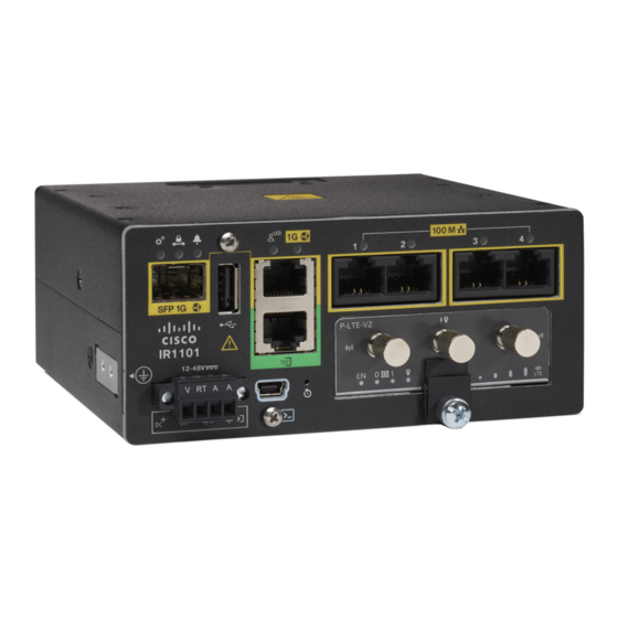
Product Overview This chapter provides an overview of the features available for the Cisco IR1101 and contains the following sections: General Description, page 11 SKU Information, page 16 Hardware Features, page 17 — Platform Features for Cisco IR1101 (Base), page 17 —... - Page 12 In addition, the Base module has a connector interface on each side to stack future modules. Figure 2 shows the IR1101 Base Module. Figure 2 Cisco IR1101 Integrated Services Router with USB covers in place USB 2.0 Port Cover Mini-USB Console Cover Figure 3 shows the front panel details of the Cisco IR1101.
- Page 13 Figure 3 Cisco IR1101 Front Panel SFP GE WAN Grounding Point (on side of device) USB 2.0 DC Power and Alarm Input RJ45 GE WAN Mini-USB Console Serial Port Reset Button FE LAN Ports 1-4 Pluggable Module Figures Figure 4 Figure 5 show an example of a Pluggable Module.
- Page 14 Figure 5 LTE Pluggable Module (with antennas) Front Panel Icons and LEDs The IR1101 uses icons to show the different features of the device. Table 1 shows Icons and their associated LEDs with descriptions. Table 2 shows the Icons without associated LEDs and their descriptions.
- Page 15 Table 1 Icons with LEDs Icon Description/Activity Icon Description/Activity System - Power and System Status. Alarm - Alarm Input Status Off — No power Off — Normal operation Green Steady on — Normal operation Red - Alarm State on the Alarm Input Green Flashing —...
-
Page 16: Sku Information
Serial Ports Warning Memory The Cisco IR1101 uses flash memory and main memory. The flash memory contains the Cisco OS software image and the boot flash contains the ROMMON boot code. The memory includes: 4 GB DRAM (soldered down) ... -
Page 17: Hardware Features
Industrial temperature [-40ºC to +60ºC, 13.8Kft (operating), 15Kft (non-operating)] One alarm input Platform Features for Cisco IR1101 (Pluggable Module) The IR1101 is designed to accept a Pluggable Module. There is additional documentation for the Pluggable Module in the Cisco 1000 Series guides that can be found here:... -
Page 18: Supported Cisco Antennas And Cables
Supported Cisco Antennas and Cables The IR1101 must have an expansion module with antenna ports installed in order to connect antennas. The base unit does not have any wireless capabilities on its own. - Page 19 The Cisco Outdoor Omnidirectional Antenna for 2G/3G/4G Cellular antenna is designed to cover domestic LTE700/Cellular/PCS/AWS/MDS, WiMAX 2300/2500, and GSM900/GSM1800/UMTS/LTE2600 bands. The Omnidirectional Outdoor Antenna is compatible with Cisco 2G, 3G, and 4G cellular devices that use a Type N connector and requires a mast-mounted outdoor antenna.
- Page 20 17 ft (5.18 meters) ANT-GPS-OUT-TNC This Cisco GPS Antenna is designed to cover a domestic frequency of 1575 MHz. This antenna is compatible with any Cisco device that uses GPS, and is compatible with active GPS antennas with DC specifications. Connector adapters may be required from TNC(m) to the required interface.
-
Page 21: Power Supply
1561.098 +/- 2.046 Power Supply The Cisco IR1101 comes with an external DC power connector. The 4-pin power entry connector (receptacle) is mounted to the unit. The 4-pin power entry mating connector (plug) is attached to the receptacle. It is removed during installation and used to connect to the DC power source, then reattached to provide power to the unit. -
Page 22: Rj45 Ports
RJ45 Ports The IR1101 supports one ISOLATED RS232 port which conforms to EIA-561 standard. The RS232 port is a DTE and its pin out is shown in Figure The RJ45 pinouts are shown in Figure 7 Figure 7 S0 Characteristics... - Page 23 Supported FE SFPs FE SFP Distance Fiber Commercial Extended Industrial 0C ~ +70C -5C ~ +85C -40C ~ +85C GLC-FE-100FX-RGD 2 km GLC-FE-100LX-RGD 10 km For the most up-to-date list of supported SFP models for Cisco Industrial Ethernet switches, see http://www.cisco.com/en/US/docs/interfaces_modules/transceiver_modules/compatibility/matrix/OL_6981.html#wp1 38176...
-
Page 25: Installing The Router
Installing the Router This chapter describes the equipment and the procedures for successfully installing the Cisco IR1101 and contains the following sections: Equipment, Tools, and Connections, page 25 Installing the Router, page 26 Installing Antennas, page 26 ... -
Page 26: Items Shipped With Your Router
1/4 in. (6 to 7mm). Installing Antennas NOTE: Before you install the Cisco IR1101 Integrated Services Router on a table, wall, or DIN rail, install the antennas on the Pluggable Module. It is difficult to install the antennas after the router is installed. - Page 27 Mounting on a Wall, Table, or Other Flat Surface The Cisco IR1101 can be mounted in a vertical or horizontal orientation. It can be mounted to a wall or other flat surface, and can also be mounted to a DIN rail.
- Page 28 Figure 1 Cisco IR1101 Mounting Bracket Align the mounting brackets (1) over the mounting holes (3) so that the larger holes on the brackets extend out over the router. Attach the brackets to the router with the 4 screws (2) provided using a Phillips head driver. Torque to 13-15 in. lbs.
- Page 29 Figure 2 Wall/Floor mounting hole dimensions with mounting brackets attached Note: Four #10-32 screws are recommended when mounting the unit with these brackets attached to the neighboring surface.
-
Page 30: Installing A Din Rail
The DIN Rail kit is ordered separately. The DIN Rail can be installed in two different orientations, horizontally and vertically. To attach the DIN rail bracket to the Cisco IR1101, follow these steps. Mounting the DIN Rail Bracket on the Router First, attach the DIN rail bracket to the back of the router. - Page 31 Figure 4 Attaching the DIN Rail Bracket for vertical mounting Note: Position the router with the ground lug facing down for vertical mounting. Figure 5 Attaching the DIN Rail Bracket for horizontal mounting Note: Position the router with the front ports facing down for horizontal mounting.
- Page 32 Once the bracket is attached to the router, it can be mounted onto the DIN Rail. Attaching the Bracket onto the DIN Rail To attach the Cisco IR101 with the bracket to a DIN rail, follow these steps. Refer to Figure 6 for details.
-
Page 33: Installing The Router Ground Connection
To install the ground connection, follow these steps: Locate the grounding lug (1) attached to the side of the Cisco IR1101. It will be attached underneath two screws. Remove the screws holding it to the router and set it aside for reuse. - Page 34 Pluggable Module remove and replace option is shown. The IR1101 may have a blank plate covering the Pluggable Module slot. This will need to be removed prior to installing the cellular modem module. The following example shows the LTE Pluggable Module.
- Page 35 Figure 10 Sim Installation Item Description Micro SIMs SIM 0 (towards the device) SIM 1 (away from device) Push in each SIM until it clicks into place. When the SIMs are installed, re-attach the access plate previously removed with a screwdriver. Torque to 2.8 to 3.8 inch-lbs (0.9-1.1 newton meter). If your Pluggable Module is the type that has a USB port, make sure that the USB cover is properly installed.
- Page 36 Figure 11 USB Port Cover Installation Tighten the latch lock screw to a torque of 2.8 to 3.8 inch-lbs (0.3 to 0.4 newton meter). Refer to Figure 12 for a finished USB cover installation. Figure 12 USB Cover Finished Installation Slide the Pluggable Module into the device as shown in Figure 13.
- Page 37 Figure 13 Pluggable Module Insert Attach your antennas to the ports on the pluggable module. There are different instructions for each antenna type, be sure to consult the antenna documentation for proper orientation and torque to install them. If no antennas are being installed on a port, make sure the caps are installed on the connector.
-
Page 39: Connecting The Router
Connecting the Router This chapter describes how to connect the IR1101 to Ethernet devices and a network. The chapter contains the following sections: Preparing to Connect the Router, page 39 Connecting a PC to the Console Port, page 39 ... -
Page 40: Connecting To Dc Power
This product requires short-circuit (overcurrent) protection, to be provided as part of the building installation. Install only in accordance with national and local wiring regulations. Statement 1045 Plugs and Pin-Outs The IR1101 ships with a DC power accessory kit. The power entry receptacle is on the IR1101. The pin-outs are shown in Figure... - Page 41 Power connector Descriptions Pin Number Name Description DC In + DC Power Positive Input DC In - DC Power Return (GND-) Alarm Common Alarm Input Wiring the DC Power To connect the DC power on your Cisco IR1101, follow these steps:...
- Page 42 Locate the power and alarm connector on the router front panel. NOTE: Your connector may not have the labels V RT A A. In the labeled connector, the pins are: V—Positive DC power connection RT— Return DC power connection A— Alarm Common A—...
-
Page 43: Verifying Connections
Verifying Connections To verify that all devices are properly connected to the router, first turn on all the connected devices, then check the LEDs. To verify router operation, refer to the Front Panel Icons and LEDs, page... -
Page 45: Technical Specifications
NOTE: Complete Regulatory Compliance and Safety Information is found online. Router Specifications Table 1 lists the operational limits of the Cisco IR1101. Operating the router outside of the limits specified is not supported. Table 1 Cisco IR1101 Specifications Description Design Specification... - Page 46 Table 1 Cisco IR1101 Specifications Description Design Specification Router DC Power Adapter Input Voltage Nominal voltage: 12V to 48V DC Min/Max voltage: 9.6V to 60V DC input Typical Currant 12V - 0.72A 24V - 0.36A 59.8V - 0.17A Typical/Maximum Power...
Need help?
Do you have a question about the IR1101 and is the answer not in the manual?
Questions and answers