Cisco Catalyst IR1101 Rugged Series Manual
- Hardware installation manual (86 pages) ,
- Manual (26 pages) ,
- User manual (26 pages)
Advertisement
5G Sub-6 GHz Support on IoT Routing
The 5G Sub-6 GHz Pluggable Interface Modules offer 5G capability to the IoT Industrial Router family. The product IDs for the pluggable modules are P-5GS6-GL and P-5GS6-R16SA. The P-5GS6-GL uses the FN980 Telit modem, and P-5GS6-R16SA uses the EM9293 modem.
 Note
Note
- IOS XE release 17.7.1 is the first software release to provide support for the P-5GS6-GL.
- IOS XE release 17.13.1 is the first software release to provide support for the P-5GS6-R16SA.
Features and Limitations
The following features and limitations apply across all IoT routing platforms unless specifically mentioned:
- IoT routing platforms support a maximum of two pluggable modules, with a combination of 5G and 4G PIMs.
- The pluggable module can be started or stopped through the CLI under exec mode. Also, it can be configured to power off the module to reduce power consumption as needed.
- The capability to disable FDD Band 30 for vehicular applications is available.
The following are product specific:
- On the IR1101 with P-5GS6-GL module:
- When plugged into the base, the module is accessible via Cellular 0/1/0, 0/1/1.
- The module is not supported on the expansion module.
5G Pluggable Interface Module Overview
- On the IR1101 with the P-5GS6-R16SA module:
- The module is software and hardware supported on both, base and expansion module.
- On the IR1800
- The cellular modems are accessible via Cellular 0/4/0, 0/4/1, 0/5/0, 0/5/1.
5G Pluggable Interface Module Overview
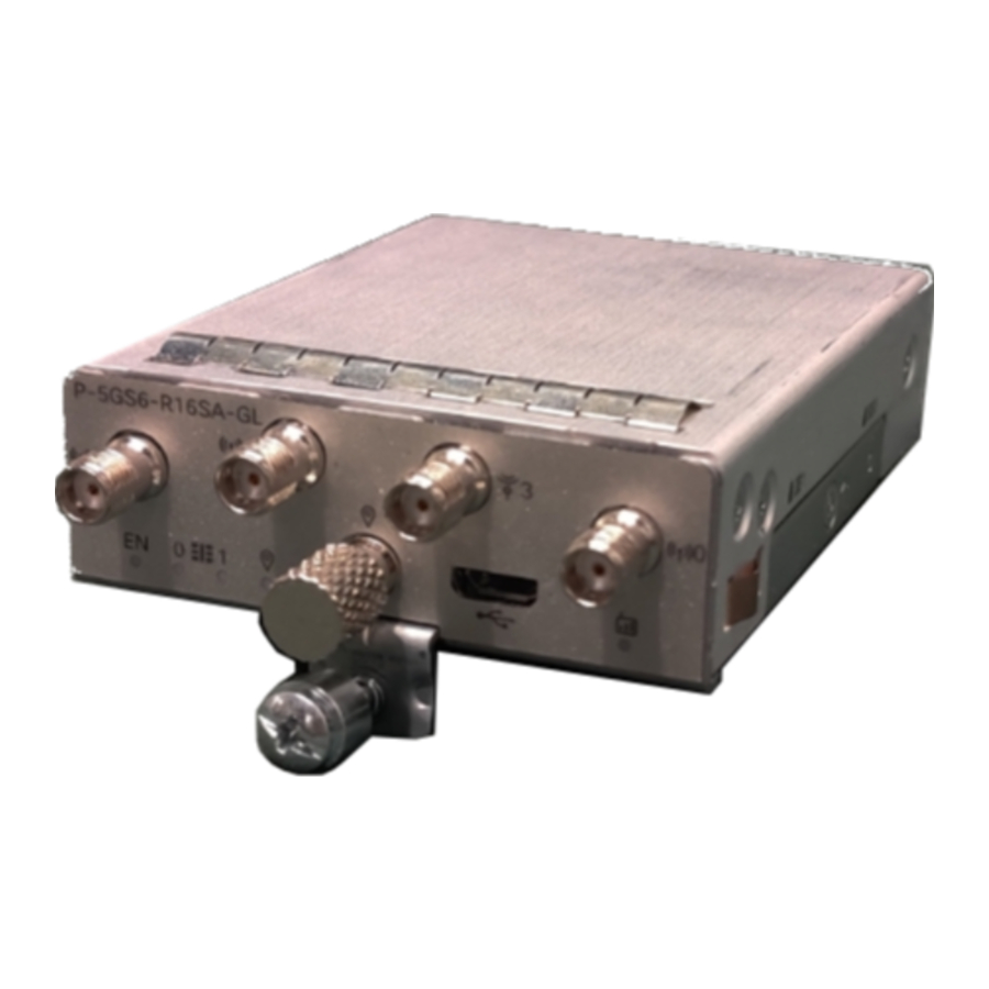
The following figure shows the face plate of P-5GS6-GL and P-5GS6-R16SA pluggable modules:

| 1 | The printed PID Note Modules P-5GS6-GL, P-5GS6-R16SA share the same face plate. |
| 2 | Antenna 1 (SMA) |
| 3 | GPS (SMA) |
| 4 | Antenna 3 (SMA) |
| 5 | Antenna 0 (SMA) |
| 6 | Antenna 2 (SMA) |
| 7 | Enable LED |
| 8 | SIM 0 LED |
| 9 | SIM 1 LED |
| 10 | GPS LED |
| 11 | M3.5 thumb-screw |
| 12 | Service LED |
LED Behaviors
The following table lists the LED indicators and their behavior. The LEDs provide a visual indication of the status and the currently selected services.
LED Indicators:
| LED | Color | Function |
| EN | Green, Yellow | Enable LED
|
| SIM0 | Green, Yellow | SIM0 LED/Activity
|
| SIM1 | Green, Yellow | SIM1 LED/Activity
|
| GPS | Green, Yellow | GPS LED
|
RF Band and Port Mapping for the P-5GS6-GL and P-5GS6-R16SA Antenna
The following table lists the RF band mapping for antenna ports.
RF Band Mapping for Antenna Ports:
Table 1: RF Band Mapping for P-5GS6-GL Module
| Antenna Port | Technology | TX | RX |
| ANT 0 | 3G WCDMA | B1, B2, B3, B4, B5, B6, B8, B9, B19 | B1, B2, B3, B4, B5, B6, B8, B9, B19 |
| 4G LTE | B1, B2, B3, B4, B5, B7, B8, B12, B13, B14, B17, B18, B19, B20, B25, B26, B28, B30, B34, B38, B39, B40, B41, B66, B71 | B1, B2, B3, B4, B5, B7, B8, B12, B13, B14, B17, B18, B19, B20, B25, B26, B28, B29, B30, B32, B34, B38, B39, B40, B41, B42, B43, B46, B48, B66, B71 | |
| 5G NR FR1 | n1, n2, n3, n5, n7, n8, n12, n20, n28, n38, n40, n41, n66, n71 | n1, n2, n3, n5, n7, n8, n12, n20, n25, n28, n38, n40, n41, n48, n66, n71, n77, n78, n79 | |
| ANT 1 | 3G WCDMA | — | B1, B2, B3, B4, B5, B6, B8, B9, B19 |
| 4G LTE | B5, B20, B42, B43, B48, B71 | B1, B2, B3, B4, B5, B7, B8, B12, B13, B14, B17, B18, B19, B20, B25, B26, B28, B29, B30, B32, B34, B38, B39, B40, B41, B42, B43, B46, B48, B66, B71 | |
| 5G NR FR1 | n5, n48, n77, n78, n79 | n1, n2, n3, n5, n7, n8, n12, n20, n25, n28, n38, n40, n41, n48, n66, n71, n77, n78, n79 | |
| ANT 2 | 3G WCDMA | — | — |
| 4G LTE | B1, B2, B3, B4, B7, B41, B66 | B1, B2, B3, B4, B7, B25, B30, B32, B34, B38, B39, B40, B41, B42, B43, B46, B48, B66 | |
| 5G NR FR1 | n1, n2, n3, n7, n25, n41, n66, n77, n78, n79 | n1, n2, n3, n7, n25, n38, n40, n41, n48, n66, n77, n78, n79 | |
| ANT 3 | 3G WCDMA | — | — |
| 4G LTE | — | B1, B2, B3, B4, B7, B25, B30, B32, B34, B38, B39, B40, B41, B42, B43, B46, B48, B66 | |
| 5G NR FR1 | — | n1, n2, n3, n7, n25, n38, n40, n41, n48, n66, n77, n78, n79 |
Table 2: RF Band Mapping for P-5GS6-R16SA Module
| Antenna Port | Technology | TX | RX |
| ANT 0 | 3G WCDMA | B1, B2, B4, B5, B8, B19 | B1, B2, B4, B5, B8, B19 |
| 4G LTE | B34, B38, B41, B66, B71 | B29, B32, B34, B38, B41, B42, B43, B46, B48 | |
| 5G NR Sub-6G | n1, n2, n3, n4, n5, n7, n8, n12, n13, n14, n17, n18, n19, n20, n25, n26, n28, n30, n39, n40, n66, n70, n71 | n1, n2, n3, n4, n5, n7, n8, n12, n13, n14, n17, n18, n19, n20, n25, n26, n28, n30, n39, n40, n66, n70, n71 | |
| ANT 1 | 3G WCDMA | — | B1, B2, B3, B4, B5, B6, B8, B9, B19 |
| 4G LTE | B42, B43, B48 | B32, B38, B41, B42, B43, B48 | |
| 5G NR Sub-6G | n48, n77, n78, n79 | n1, n2, n3, n4, n7, n25, n30, n38, n39, n40, n41, n48, n66, n70, n75, n76, n77, n78, n79 | |
| ANT 2 | 3G WCDMA | — | B1, B2, B4, B5, B8, B19 |
| 4G LTE | B41 | B29, B32, B34, B38, B41, B42, B43, B48 | |
| 5G NR Sub-6G | n38, n41, n77, n78 | n1, n2, n3, n4, n5, n7, n8, n12, n13, n14, n17, n18, n19, n20, n25, n26, n28, n29, n30, n38, n39, n40, n41, n48, n66, n70, n71, n75, n76, n77, n78, n79 | |
| ANT 3 | 3G WCDMA | — | — |
| 4G LTE | B42, B43, B48 | B32, B38, B41, B42, B43, B46, B48 | |
| 5G NR Sub-6G | n48, n77, n78, n79 | n1, n2, n3, n4, n7, n25, n30, n38, n39, n40, n41, n48, n66, n70, n75, n76, n77, n78, n79 |
Port Mappings for 5G-ANTM-0-4-B on the P-5GS6-GL and P-5GS6-R16SA PIMs
The following table lists the port mappings using the 5G-ANTM-O-4-B antenna as an example, mapping to the ports on the P-5GS6-GL and P-5GS6-R16SA pluggable module.
| 5G-ANTM-O-4-B | P-5GS6-GL, P-5GS6-R16SA |
| MAIN 0 (LTE1) | ANT 0 |
| MAIN 1 (LTE3) | ANT 1 |
| DIV 0 (LTE2) | ANT 2 |
| DIV 1 (LTE4) | ANT 3 |
| GNSS | GPS |
The following link contains the antenna specifications and installation instructions for 5G NR (5G-ANTM-O-4-B):
https://www.cisco.com/c/en/us/td/docs/routers/connectedgrid/antennas/installing-combined/b-cisco-industrial-routers-and-industrial-wireless-access-points-antenna-guide/m-5g-antm-04b.html#Cisco_Generic_Topic.dita_e780a6fe-fa46-4a00-bd9d-1c6a98b7bcb9
Attaching an Antenna
To attach the antenna in the Pluggable Interface Module, perform the below steps:
Figure: Attaching 5G NR Antenna (5G-ANTM-O4-B) to P-5GS6-GL, P-5GS6-R16SA PIM

- Attach each SMA cable to the ports as indicated in the table mappings.
- Ensure that you tighten and secure each SMA cable into the SMA connector on the PIM.
Documents / ResourcesDownload manual
Here you can download full pdf version of manual, it may contain additional safety instructions, warranty information, FCC rules, etc.
Advertisement


Need help?
Do you have a question about the Catalyst IR1101 Rugged Series and is the answer not in the manual?
Questions and answers