Cisco IR829 Hardware Installation Manual
Industrial integrated services router
Hide thumbs
Also See for IR829:
- Product manual (16 pages) ,
- Hardware installation manual (87 pages) ,
- Hardware installation manual (69 pages)
Table of Contents
Advertisement
Advertisement
Table of Contents

Related Manuals for Cisco IR829


Summary of Contents for Cisco IR829
- Page 1 Cisco IR829 Industrial Integrated Services Router Hardware Installation Guide July 2017 Americas Headquarters Cisco Systems, Inc. 170 West Tasman Drive San Jose, CA 95134-1706 http://www.cisco.com Tel: 408 526-4000 800 553-NETS (6387) Fax: 408 527-0883 Text Part Number:...
- Page 2 ITS SUPPLIERS HAVE BEEN ADVISED OF THE POSSIBILITY OF SUCH DAMAGES. Cisco and the Cisco logo are trademarks or registered trademarks of Cisco and/or its affiliates in the U.S. and other countries. To view a list of Cisco trademarks, go to this URL: www.cisco.com/go/trademarks.
-
Page 3: Table Of Contents
Platform Features for Cisco IR829 ........ - Page 4 Supported Dual Band Cisco WiFi Antenna Use Case 3 ......31 7 in 1 Antenna Configuration for Transportation .
-
Page 5: Preface
Obtaining Documentation and Submitting a Service Request, page 10 Objective This guide provides an overview and explains how to install, connect, and perform initial configuration for the Cisco IR829. Previous versions contained additional configuration information which has now been relocated to the Cisco IR800 Integrated Services Router Software Configuration Guide. -
Page 6: Conventions
Preface Conventions Chapter 2 Chapter 3, “Installing the Router” Lists the items shipped with the router, the equipment and tools necessary for installing the router, the safety warnings and guidelines, and the procedures for installing the router. Chapter 3 Chapter 4, “Connecting the Router” Describes typical connections for the router, procedures for connecting the router to various devices, and how to verify the connections. - Page 7 Preface Safety Warnings Varoitus TÄRKEITÄ TURVALLISUUSOHJEITA Tämä varoitusmerkki merkitsee vaaraa. Tilanne voi aiheuttaa ruumiillisia vammoja. Ennen kuin käsittelet laitteistoa, huomioi sähköpiirien käsittelemiseen liittyvät riskit ja tutustu onnettomuuksien yleisiin ehkäisytapoihin. Turvallisuusvaroitusten käännökset löytyvät laitteen mukana toimitettujen käännettyjen turvallisuusvaroitusten joukosta varoitusten lopussa näkyvien lausuntonumeroiden avulla. SÄILYTÄ...
- Page 8 Preface Safety Warnings Aviso INSTRUÇÕES IMPORTANTES DE SEGURANÇA Este símbolo de aviso significa perigo. Você está em uma situação que poderá ser causadora de lesões corporais. Antes de iniciar a utilização de qualquer equipamento, tenha conhecimento dos perigos envolvidos no manuseio de circuitos elétricos e familiarize-se com as práticas habituais de prevenção de acidentes.
- Page 9 Preface Safety Warnings Aviso INSTRUÇÕES IMPORTANTES DE SEGURANÇA Este símbolo de aviso significa perigo. Você se encontra em uma situação em que há risco de lesões corporais. Antes de trabalhar com qualquer equipamento, esteja ciente dos riscos que envolvem os circuitos elétricos e familiarize-se com as práticas padrão de prevenção de acidentes.
- Page 10 Preface Safety Warnings...
- Page 11 Electrical Appliance and Material Safety Law prohibits the use of UL-certified cables (that have the “UL” shown on the code) for any other electrical devices than products designated by CISCO. The use of cables that are certified by Electrical Appliance and Material Safety Law (that have “PSE”...
-
Page 12: Related Documentation
Subscribe to the What’s New in Cisco Product Documentation as a Really Simple Syndication (RSS) feed and set content to be delivered directly to your desktop using a reader application. The RSS feeds are a free service and Cisco currently supports RSS Version 2.0. -
Page 13: Product Overview
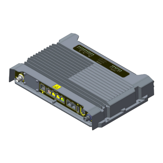
Product Overview This chapter provides an overview of the features available for the Cisco IR829 Integrated Services Routers (ISRs) and contains the following sections: General Description, page 11 SKU Information, page 18 Hardware Features, page 18 ... - Page 14 Product Overview General Description Figure 1 Cisco IR829 Integrated Services Router Figure 2 shows the front panel details of the Cisco IR829 Single Modem. Figure 2 Cisco IR829 Front Panel Single Modem CELLULAR 0 AUX Serial Ports Limited Modularity Slot USB 2.0 type-A Port...
- Page 15 DC Power section for pin-outs. Gigabit Ethernet LAN/PoE (RJ45) WLAN ANT 0 2.4/5GHz Figure 4 shows the back panels details of the Cisco IR829 Single Modem. Figure 4 Cisco IR829 Back Panel Single Modem WLAN ANT 0 5GHz Denotes SIM card order, SIM0 on top and SIM1 on bottom.
- Page 16 GPS SMA NOTE: Behind the SIM Door Assembly, there is a reset switch(1), Mini USB console port(2), and Dual SIM slots(3). See Figure 6 details Figure 6 Behind the SIM Door Figure 7 shows the top of the Cisco IR829.
-
Page 17: Leds
Product Overview General Description Figure 7 Cisco IR829 Top Cover (single modem version) Figure 8 shows the LED detail from the Dual Modem SKU. Single Modem SKUs will only have Cellular 0 LEDs. Figure 8 Cisco IR829 LED Detail The following section shows a detailed description of the LEDs. - Page 18 Product Overview General Description Table 1 LED Descriptions Activity Description Power Status Off — No power Green Steady on — Normal operation Green Flashing — Boot up phase or in ROM Monitor mode Amber Steady on — System shutdown due to under or over voltage conditions Amber Flashing —...
-
Page 19: Memory
Memory The Cisco IR829 uses flash memory and main memory. The flash memory contains the Cisco IOS software image and the boot flash contains the ROMMON boot code. All memory components are factory default and not upgradeable by the end user. -
Page 20: Sku Information
Single Modem LTE for Hong Kong IR829GW-LTE-LA-NK9 Single Modem LTE for Panama Hardware Features This section provides an overview of the following hardware features for the Cisco IR829. Platform Features for Cisco IR829, page 18 Antennas, page 20 ... -
Page 21: Platform Features For Cisco Ir829
8GB (4GB usable) “eMMC” bulk storage flash 4-port GE LAN switch, optional PoE 802.3at (30W max) for Cisco devices only. NOTE: The software does not support PoE negotiation over LLDP, only CDP. Therefore, PoE will only power up Cisco devices, WAN 1 GE SFP ... -
Page 22: Antennas
Software Configuration Guide. The IR829 differs from traditional IOS routers. Antennas The IR829 has RP-TNC connectors for Wi-Fi and TNC connectors for cellular. The IR829 also has an SMA connector for a GPS antenna. Standard antennas are: Two multiband swivel-mount dipole antennae (ANT-4G-DP-IN-TNC) and one extender (4G-AE010-R). - Page 23 Ground plane Cisco recommends having a 1 foot ground plane under both the 5-in-1 and 2-in-1 antennas. In case of a metal vehicle roof, the roof itself shall be the ground plane. While Cisco has investigated the effects of ground plane and no ground plane, wireless performance was certified with the 1 foot ground plane.
-
Page 24: Modem Support
The following section shows some examples of different installation scenarios. Modem Support The Cisco IR800 series Industrial routers use the MC73XX and MC74XX series modems. The software download page can be found here: https://software.cisco.com/download/navigator.html?mdfid=286288566&flowid=76082 NOTE: Be sure to select the correct firmware download for your carrier. -
Page 25: Lte Radio Cables/Antennas Use Case 2
R/A-TNC(m) to N(m), LMR-240-FR/CMR, 5', qty 2 R/A-TNC(m) to N(m), LMR-240-FR/CMR, 10', qty 2 R/A-TNC(m) to N(m), LMR-240-FR/CMR, 15', qty 2 R/A-TNC(m) to N(m), LMR-240-FR/CMR, 20', qty 2 Note These cables not available from Cisco Adapter and/or None Lightning Arrestor External Cable... - Page 26 Product Overview Supported Cisco Antennas and Cables Table 7 4G/LTE Radio Cables/Antennas Use Case 3 Item Description Adapter and/or None Lightning Arrestor External Cable None Antenna Quantity of 2 4G Indoor Swivel Mount Dipole, 0 dBi, TNC(m), white ANT-4G-DP-IN-TNC...
-
Page 27: Lte Radio Cables/Antennas Use Case 4
Product Overview Supported Cisco Antennas and Cables 4G/LTE Radio Cables/Antennas Use Case 4 Table 8 4G/LTE Radio Cables/Antennas Use Case 4 Item Description Antenna Arrangement Front Panel Swivel Mount 4G-LTE dipoles Internal Cable Chose one of 3 scenarios: None ... -
Page 28: Lte Radio Cables/Antennas Gps Use Case 1
Need one with integrated coax cable and SMA(m) connector, 17ft, outdoor, IP67 Quantity of 1 GPS-ACT-ANTM-SMA= Single Band Cisco WiFi Antenna Supported Single Band Cisco WiFi Antenna Use Case 1 Table 11 Single Band Cisco WiFi Antenna Use Case 1 Item Description... -
Page 29: Supported Single Band Cisco Wifi Antenna Use Case 2
Product Overview Supported Cisco Antennas and Cables Supported Single Band Cisco WiFi Antenna Use Case 2 Table 12 Single Band Cisco WiFi Antenna Use Case 2 Item Description Antenna Arrangement Single Band, Single Element, Ceiling Mounted Antennas Radio Module Dual Band Simultaneous 802.11n 2x2 MIMO WiFi... -
Page 30: Supported Single Band Cisco Wifi Antenna Use Case 4
AIR-ANT24020V-R 2x Single Band, Ceiling Mount Omni, 36" LONG RG-58 cable with RP-TNC (plug), 5.2dBi @ 5 GHz AIR-ANT5160V-R Supported Single Band Cisco WiFi Antenna Use Case 4 Table 14 Single Band Cisco WiFi Antenna Use Case 4 Item... -
Page 31: Supported Single Band Cisco Wifi Antenna Use Case 5
1x Single Band, Dual Element, Wall Mount Patch, 18" LONG RG-58 cables with RP-TNC, 7.0dBi @ 5 GHz (INDOOR/OUTDOOR) AIR-ANT5170P-R Supported Single Band Cisco WiFi Antenna Use Case 5 Table 15 Single Band Cisco WiFi Antenna Use Case 5 Item... -
Page 32: Dual Band Cisco Wifi Antenna
1x Single Band, Dual Element, Wall Mount Patch, 18" LONG RG-58 cable with N(m), 14dBi @ 5 GHz AIR-ANT5114P2M-N Dual Band Cisco WiFi Antenna Supported Dual Band Cisco WiFi Antenna Use Case 1 Table 16 Dual Band Cisco WiFi Antenna Use Case 1 Item... -
Page 33: Supported Dual Band Cisco Wifi Antenna Use Case 3
The 5-in1 Quinta antenna and the 2-in1 WiFi antennas need to be separated 18" between mounting hole centers of the two antennas. Extension Cable No extension cables are required if the IR829 is located within ~1.0ft of 5-in-1 antenna, and ~2.0ft of WiFi 2-in-1 antenna. If these conditions are not met, this deployment requires the following extension cables:... - Page 34 Product Overview Supported Cisco Antennas and Cables Qty 2X LMR-400-DB TNC(m)-R/A - TNC(f), 5ft 4G-CAB-LMR400-5 — OR Qty 2X LMR-400-DB TNC(m)-R/A - TNC(f), 10ft G-CAB-LMR400-10 — OR Qty 2X LMR-400-LLPL plenum / indoor only TNC(m)-R/A - TNC(f), 20ft ...
-
Page 35: Transportation Use Case 2
SUPPLIED BY CISCO) Extension Cable No extension cables are required if the IR829 is located within ~1.0ft of 5-in-1 antenna, and ~2.0ft of WiFi 2-in-1 antenna. If these conditions are not met, this deployment requires the following extension cables: Cellular extension cables (2 ports) Qty 2X LMR-400-DB TNC(m)-R/A - TNC(f), 5ft ... -
Page 36: Power Supply
4-pin locking Molex power connector, Cisco part number 29-2562-01. There is an external AC to DC power adapter for the IR829. It meets ITE standards and operating temperature range of -20C to 60C, but is not suited for industrial environment. Part Number is IR829-PWR125W-AC. - Page 37 Product Overview SFP Modules Table 19 Maximum Operating Temperature Type of SFP Module Model Rugged and Industrial SFPs GLC-SX-MM-RGD with digital optical monitoring –40 to 185°F (–40 to 85°C) (DOM) support GLC-LX-SM-RGD with digital optical monitoring (DOM) support GLC-ZX-SM-RGD with digital optical monitoring (DOM) support Commercial SFPs GLC-SX-MM...
-
Page 38: Rj45 Ports
NOTE: Auto negotiation is not supported on these SFPs. For minimum software requirements, refer to the Release Notes for your platform. For the most up-to-date list of supported SFP models for Cisco Industrial Ethernet switches, see http://www.cisco.com/en/US/docs/interfaces_modules/transceiver_modules/compatibility/matrix/OL_6981.html#wp138176 RJ45 Ports Two RJ45 serial ports are provided to control and monitor RS232 or RS485 equipment. Serial port 0 can be configured for either RS232 DCE or RS485. -
Page 39: Rs485 Port
Product Overview RJ45 Ports RS485 Port The RS485 pin out follows EIA-561 standard. There is no standard for RJ-45 connector used for RS485. In the IR809, the pin-pairs 1,2 and 3,6 were chosen for RS485 so that an Ethernet CAT-5 with these standard twisted-pair pin assignments can be used. Figure Figure 10 shows the characteristics of the S0 and S1 ports. - Page 40 Product Overview RJ45 Ports...
-
Page 41: Installing The Router
Installing the Router This chapter describes the equipment and the procedures for successfully installing the Cisco IR829 and contains the following sections: Equipment, Tools, and Connections, page 39 Installing the Router, page 40 CAUTION: Do not place anything on top of the router that weighs more than 10 pounds (4.5 kilograms), and do not stack routers on a desktop. -
Page 42: Items Shipped With Your Router
Installing the Router This section describes how to install the Cisco IR829. This router can be installed on a table top or other flat horizontal surface mounted on a wall or DIN rail. -
Page 43: Warnings
NOTE: High Temperature SIMs are required for 4G operations if the Ambient temperature is above 95F (35C) To access the SIM card in the Cisco IR829, follow these steps: Place the router on its bottom and ensure that any installed antennas are carefully oriented. -
Page 44: Installing Antennas
Replace the panel and the screws. Installing Antennas NOTE: Before you install the Cisco IR829 Integrated Services Router on a table, wall, or DIN rail, install the antennas on the front panel. It is difficult to install the antennas after the router is installed. -
Page 45: Mounting On A Wall, Table, Or Other Flat Surface
Installing the Router Mounting on a Wall, Table, or Other Flat Surface The Cisco IR829 has mounting holes on the bottom of the chassis for mounting the unit on a wall or other vertical surface. The attachment hardware is provided. -
Page 46: Installing The Router Ground Connection
To install the ground connection, follow these steps: Locate the grounding lug attached to the back of the Cisco IR829. It will be attached underneath two screws. Remove the screws holding it to the router and set it aside for reuse. - Page 47 Installing the Router Installing the Router Figure 5 Chassis Ground Connection Points Connect the other end of the ground wire to a known reliable earth ground point at your site. If you are using this router in a vehicle, attach the ring terminal to the chassis using one of the screws provided and the green or green and yellow striped wire.
- Page 48 Installing the Router Installing the Router...
-
Page 49: Connecting The Router
Connecting the Router This chapter describes how to connect Cisco IR829 Integrated Services Router (ISRs) to Ethernet devices and a network. The chapter contains the following sections: Preparing to Connect the Router, page 47 Connecting a PC, Server, or Workstation, page 47 ... -
Page 50: Connecting A Terminal Or Pc To The Console Port
Connecting the Router Connecting a Terminal or PC to the Console Port Figure 1 Connecting a Server, PC, or Workstation Ethernet cable RJ-45 port on the PC, Server, or Workstation Ethernet switch port on the router Connect the other end of the cable to the RJ-45 port on the network interface card (NIC) that is installed in the PC, server, or workstation. -
Page 51: Connecting To Dc Power
Plugs and Pin-Outs The IR829 ships with a DC power accessory kit that contains a 4-pin locking connector and pins to use for the power connections. Four contacts are supplied, but only three are used. One is a spare. The Molex power connector is Cisco part number 29-2562-01. -
Page 52: Wiring The Dc Power
Wires wound at 1 twist per inch Wiring the DC Power To connect the DC power on your Cisco IR829, follow these steps: Identify the DC power source and measure 4 strands of copper wire 16 AWG (1.29mm) long enough to connect to the DC power source. -
Page 53: Vehicle Connections
When connecting to automotive power, it is expected that the ignition output will be +12 VDC. The DC In and DC Out leads can be directly connected to the battery, but it is recommended that they be connected after a fuse. NOTE: For details about the Ignition Power Management Software and setting it up, see the Cisco IR800 Integrated Services Router Software Configuration Guide. - Page 54 Slow Flash — Module is powered on and searching for connection Fast Flash — Module is transmitting or receiving. NOTE: There are single LTE and dual LTE SKUs available with the IR829. See Figure 8 on page -15 for details.
-
Page 55: Technical Specifications
Regulatory Compliance and Safety Information for Cisco 800 Series and SOHO Series Routers. Router Specifications Table 1 lists the operational limits of the Cisco IR829. Operating the router outside of the limits specified is not supported. Table 1 Cisco IR829 Specifications Description... - Page 56 Technical Specifications Router Specifications Table 1 Cisco IR829 Specifications (continued) Description Design Specification Certifications Standard Safety Certifications UL 60950-1, 2nd edition; CAN/CSA C22.2 No. 60950-1, 2nd edition, EN 60950-1, 2nd edition; CB to IEC 60950-1, 2nd edition with all group differences and national deviations...
Need help?
Do you have a question about the IR829 and is the answer not in the manual?
Questions and answers