Cisco IR829 Hardware Installation Manual
Industrial integrated services router
Hide thumbs
Also See for IR829:
- Product manual (16 pages) ,
- Hardware installation manual (56 pages) ,
- Hardware installation manual (87 pages)
Table of Contents
Advertisement
Quick Links
Cisco IR829 Industrial Integrated Services Router Hardware Installation
Guide
First Published: 2017-10-11
Last Modified: 2018-10-25
Americas Headquarters
Cisco Systems, Inc.
170 West Tasman Drive
San Jose, CA 95134-1706
USA
http://www.cisco.com
Tel: 408 526-4000
800 553-NETS (6387)
Fax: 408 527-0883
Advertisement
Table of Contents

Subscribe to Our Youtube Channel
Related Manuals for Cisco IR829


Summary of Contents for Cisco IR829
- Page 1 Cisco IR829 Industrial Integrated Services Router Hardware Installation Guide First Published: 2017-10-11 Last Modified: 2018-10-25 Americas Headquarters Cisco Systems, Inc. 170 West Tasman Drive San Jose, CA 95134-1706 http://www.cisco.com Tel: 408 526-4000 800 553-NETS (6387) Fax: 408 527-0883...
- Page 2 Any use of actual IP addresses or phone numbers in illustrative content is unintentional and coincidental. Cisco and the Cisco logo are trademarks or registered trademarks of Cisco and/or its affiliates in the U.S. and other countries. To view a list of Cisco trademarks, go to this URL: www.cisco.com trademarks.
- Page 3 Objective This guide provides an overview and explains how to install, connect, and perform initial configuration for the Cisco IR829. Previous versions contained additional configuration information which has now been relocated to the Cisco IR800 Integrated Services Router Software Configuration Guide.
-
Page 4: Safety Warnings
Verfahren zur Vorbeugung vor Unfällen vertraut. Suchen Sie mit der am Ende jeder Warnung angegeb Anweisungsnummer nach der jeweiligen Übersetzung in den übersetzten Sicherheitshinweisen, die zusam mit diesem Gerät ausgeliefert wurden. BEWAHREN SIE DIESE HINWEISE GUT AUF. Cisco IR829 Industrial Integrated Services Router Hardware Installation Guide... - Page 5 Använd det nummer som finns i slutet av varje varning för dess översättning i de översatta säkerhetsvarningar som medföljer denna anordning. SPARA DESSA ANVISNINGAR Cisco IR829 Industrial Integrated Services Router Hardware Installation Guide...
- Page 6 Brug erklæringsnumm efter hver advarsel for at finde oversættelsen i de oversatte advarsler, der fulgte med denne enhed. GEM DISSE ANVISNINGER Cisco IR829 Industrial Integrated Services Router Hardware Installation Guide...
- Page 7 Preface Safety Warnings Cisco IR829 Industrial Integrated Services Router Hardware Installation Guide...
- Page 8 Material Safety Law prohibits the use of UL-certified cables (that have the “UL” shown on the code) for any other electrical devices than products designated by CISCO. The use of cables that are certified by Electrical Appliance and Material Safety Law (that have “PSE” shown on the code) is not limited to CISCO-designated products.
-
Page 9: Related Documentation
Full Reader Search window to search multiple PDF files simultaneously and to change case sensitivity and other options. Adobe Reader’s online help has more information about how to search PDF documents. Cisco IR829 Industrial Integrated Services Router Hardware Installation Guide... -
Page 10: Obtaining Documentation And Submitting A Service Request
Obtaining Documentation and Submitting a Service Request For information on obtaining documentation, submitting a service request, and gathering additional information, see the monthly What’s New in Cisco Product Documentation , which also lists all new and revised Cisco technical documentation, at: http://www.cisco.com/en/US/docs/general/whatsnew/whatsnew.html... -
Page 11: Product Overview
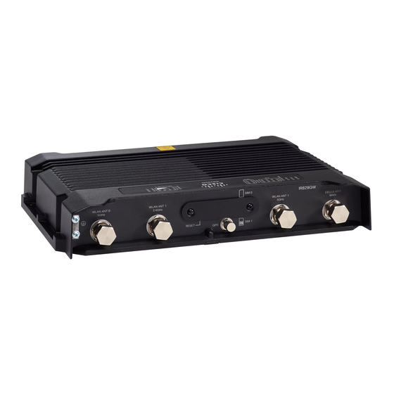
C H A P T E R Product Overview This chapter provides an overview of the features available for the Cisco IR829 Integrated Services Routers (ISRs) and contains the following sections: • Product Overview, on page 9 Product Overview This chapter provides an overview of the features available for the Cisco IR829 Integrated Services Routers... - Page 12 Product Overview General Description Figure 1: Cisco IR829 Integrated Services Router Figure 2: Cisco IR829 Front Panel Single Modem, on page 10 shows the front panel details of the Cisco IR829 Single Modem. Figure 2: Cisco IR829 Front Panel Single Modem...
- Page 13 Gigabit Ethernet WLAN ANT 0 2.4/5GHz LAN/PoE (RJ45) Figure 4: Cisco IR829 Back Panel Single Modem, on page 11 shows the back panels details of the Cisco IR829 Single Modem. Figure 4: Cisco IR829 Back Panel Single Modem...
- Page 14 Figure 6: Behind the SIM Door, on page 12 for details Figure 6: Behind the SIM Door Figure 7: Cisco IR829 Top Cover (single modem version), on page 13 shows the top of the Cisco IR829. Cisco IR829 Industrial Integrated Services Router Hardware Installation Guide...
- Page 15 Product Overview LEDs Figure 7: Cisco IR829 Top Cover (single modem version) Figure 8: Cisco IR829 LED Detail, on page 13 shows the LED detail from the Dual Modem SKU. Single Modem SKUs will only have Cellular 0 LEDs. Figure 8: Cisco IR829 LED Detail The following section shows a detailed description of the LEDs.
- Page 16 Amber Steady on — 54V POE power supply good, but one or more POE ports has a fault. Off — No VPN tunnel Steady on — At least one VPN tunnel is Cisco IR829 Industrial Integrated Services Router Hardware Installation Guide...
- Page 17 Steady Green — One wireless client is associated. CELLULAR0/CELLULAR1 RSSI The RSSI LEDs are a 3 LED bar graph to indicate signal strength. Their functionality is described in the RSSI LED figure below. Cisco IR829 Industrial Integrated Services Router Hardware Installation Guide...
- Page 18 Green Memory The Cisco IR829 uses flash memory and main memory. The flash memory contains the Cisco IOS software image and the boot flash contains the ROMMON boot code. All memory components are factory default and not upgradeable by the end user.
-
Page 19: Sku Information
Cisco 829 Industrial Integrated Services Routers Data Sheet Hardware Features This section provides an overview of the following hardware features for the Cisco IR829. Platform Features for Cisco IR829 The following lists the hardware platform features for the Cisco IR829. - Page 20 Table 5: Wi-Fi domains Country Wi-Fi Cellular Carrier Domain IR829GWR-LTE-LA-QK9 Japan NTT, DoCoMo, Softbank, KDDI IR829GW-LTE-LA-DK9 India IR829GW-LTE-LA-ZK9 Australia, New Zealand Telstra, Spark IR829GW-LTE-LA-KK9 Korea IR829GW-LTE-LA-HK9 China IR829GW-LTE-LA-LK9 Malaysia IR829GW-LTE-LA-SK9 Hong Kong IR829GW-LTE-LA-NK9 Panama Cisco IR829 Industrial Integrated Services Router Hardware Installation Guide...
-
Page 21: Reset Button
Integrated Services Router Software Configuration Guide. The IR829 differs from traditional IOS routers. Antennas The IR829 has RP-TNC connectors for Wi-Fi and TNC connectors for cellular. The IR829 also has an SMA connector for a GPS antenna. Standard antennas are: •... - Page 22 Ground plane Cisco recommends having a 1 foot ground plane under both the 5-in-1 and 2-in-1 antennas. In case of a metal vehicle roof, the roof itself shall be the ground plane. While Cisco has investigated the effects of ground plane and no ground plane, wireless performance was certified with the 1 foot ground plane.
-
Page 23: Modem Support
MIMO capable products are giving up significant wireless performance in both throughput and robustness of the link. • The individual 4G antenna cables on the 5-in-1 antenna can be connected to either cellular port of IR829. There is no one-to-one assignment requirement. - Page 24 R/A-TNC(m) to N(m), LMR-240-FR/CMR, 10', qty 2 R/A-TNC(m) to N(m), LMR-240-FR/CMR, 15', qty 2 R/A-TNC(m) to N(m), LMR-240-FR/CMR, 20', qty 2 Note: These cables not available from Cisco Adapter and/or Lightning None Arrestor External Cable None Cisco IR829 Industrial Integrated Services Router Hardware Installation Guide...
- Page 25 • PID: 4G-AE010-R • 10ft extension base for TNC dipole antennas • Quantity of 2 • PID: 4G-AE015-R • 15ft extension base for TNC dipole antennas Adapter and/or Lightning Arrestor None Cisco IR829 Industrial Integrated Services Router Hardware Installation Guide...
- Page 26 Indoor Cable None Adapter and/or Lightning Arrestor None External Cable None Antenna GPS Antenna Need one with integrated coax cable and SMA(m) connector, 17ft, outdoor, IP67 Quantity of 1 • GPS-ACT-ANTM-SMA= Cisco IR829 Industrial Integrated Services Router Hardware Installation Guide...
- Page 27 2x Single Band, Ceiling Mount Omni, 36” LONG RG-58 cable with RP-TNC (plug), 5.2dBi @ 2.4 GHz • AIR-ANT1728 2x Single Band, Ceiling Mount Omni, 36" LONG RG-58 cable with RP-TNC (plug), 5.2dBi @ 5 GHz • AIR-ANT5160V-R Cisco IR829 Industrial Integrated Services Router Hardware Installation Guide...
- Page 28 Single Band, Dual Element, Wall Mounted Antennas Radio Module Dual Band Simultaneous 802.11n 2x2 MIMO WiFi Connectors: 4x RP-TNC (jack) Adapter and/or Lightning None, or: Arrestor RP-TNC lightning arrestor, qty 4 • AIR-ACC245LA-R Indoor Cable None Cisco IR829 Industrial Integrated Services Router Hardware Installation Guide...
- Page 29 Dual Band Simultaneous 802.11n 2x2 MIMO WiFi Connectors: 4x RP-TNC (jack) Adapter and/or Lightning N(f) to N(f), RF-adapter, qty 4 Arrestor • AIR-ACC370-NF-NF Indoor Cable None External Cable RP-TNC(plug) to N(m)-R/A, LMR-240-DB, 5', qty 4 • AIR-CAB005LL-R-N Cisco IR829 Industrial Integrated Services Router Hardware Installation Guide...
-
Page 30: Dual Band Cisco Wifi Antenna
External Cable Antenna 1x Dual Band, Dual Element per Band, Omni, 18" LONG RG-58 cables with RP-TNC (plug), 2.0dBi @ 2.4 GHz (2 ports), 3.0dBi @ 5 GHz (2 ports) • AIR-ANT2451V-R Cisco IR829 Industrial Integrated Services Router Hardware Installation Guide... -
Page 31: In 1 Antenna Configuration For Transportation
Extension Cable No extension cables are required if the IR829 is located within ~1.0ft of 5-in-1 antenna, and ~2.0ft of WiFi 2-in-1 antenna. If these conditions are not met, this deployment requires the following extension cables:... - Page 32 Transportation Use Case 2 Antenna Arrangement 7 x RF ports, with the IR829 deployed in a transportation application. (Alternate Configuration, can be used in case the application calls for the WiFi antennas to be separate from the LTE antenna for example. a ceiling mount WLAN).
- Page 33 (NOT SUPPLIED BY CISCO) Extension Cable No extension cables are required if the IR829 is located within ~1.0ft of 5-in-1 antenna, and ~2.0ft of WiFi 2-in-1 antenna. If these conditions are not met, this deployment requires the following extension cables:...
-
Page 34: Power Supply
• 4-pin locking Molex power connector, Cisco part number 29-2562-01. There is an external AC to DC power adapter for the IR829. It meets ITE standards and operating temperature range of -20C to 60C, but is not suited for industrial environment. Part Number is IR829-PWR125W-AC. - Page 35 • Copper (fixed speed of 1Gbps) • GLC-FE-T= • Copper 100Mbps NOTE: Auto negotiation is not supported on these SFPs. For minimum software requirements, refer to the Release Notes for your platform. Cisco IR829 Industrial Integrated Services Router Hardware Installation Guide...
-
Page 36: Serial Rj45 Ports
Product Overview Serial RJ45 Ports For the most up-to-date list of supported SFP models for Cisco Industrial Ethernet switches, see http://www.cisco.com/en/US/docs/interfaces_modules/transceiver_modules/compatibility/matrix/OL_6981.html#wp138176 Serial RJ45 Ports Two RJ45 serial ports are provided to control and monitor RS232 or RS485 equipment. Serial port 0 can be configured for either RS232 DCE or RS485 half or full duplex. - Page 37 Cisco refers to the signal on pin 1 as DSR. Use the show interface async 0 (or 1) from the IOS command line will give you the state of the modem control signals on the last line: DCD=up...
-
Page 38: Rs232 Port
Serial 0 and Serial 1 ports on the IR809 and IR829. It is the direction of the data and flow control signals that differs. The RS232-DCE port, Serial 0, is designed to be connected to a far-end DTE port, or to another DCE port via a crossover (null-modem) cable. - Page 39 Ring Indicator, (used as in IOS) DSR in IOS) Optional use. Data Carrier Detect Data Terminal Ready SG (COM) Signal Ground (Common) Received Data Transmitted Data Clear To Send Request To Send Cisco IR829 Industrial Integrated Services Router Hardware Installation Guide...
-
Page 40: Serial 0 Configured As An Rs485 Port
The RS232 pin out follows the EIA-561 standard, however, there is no standard for an RJ-45 connector used for RS485. In the IR809 and IR829, the pin-pairs 1,2 and 3,6 were chosen for RS485 so that an Ethernet CAT-5 with the standard twisted-pair pin assignments can be used. -
Page 41: Terminating Resistor
Wiring Recommendations for RS-485 Networks: • Typically Category 5 Ethernet cable is suitable for RS-485. • Shielded cable is desirable and the shield should be grounded at on end if it is used. Cisco IR829 Industrial Integrated Services Router Hardware Installation Guide... -
Page 42: Serial Port Control
• Fail-safe bias resistors should be placed at the receiver end of the transmission line. Serial Port Control The entire layer 1 configuration of the IR809 / IR829 serial ports is done in IOS under the following constructs. The following example shows values other than the defaults to show most of the IOS keywords. - Page 43 To switch Serial 0 from RS232 to RS485, the configuration is set in interface Async0. The RS485 half or full duplex is set there as well. For example: RS485 HALF DUPLEX - Serial 0 Only: interface Async0 no ip address encapsulation relay-line half-duplex media-type rs485 Cisco IR829 Industrial Integrated Services Router Hardware Installation Guide...
-
Page 44: Additional Resources
<- default– will not print for a “show run” command media-type rs485 Additional Resources How Far and How Fast Can You Go with RS-485: https://www.maximintegrated.com/en/app-notes/index.mvp/id/3884 Interface Circuits for TIA/EIA-232-F – Design Notes: http://www.ti.com/lit/an/slla037a/slla037a.pdf RS232 Quick Guide http://cds.linear.com/docs/en/product-selector-card/RS232%20Quick%20Guide.pdf Cisco IR829 Industrial Integrated Services Router Hardware Installation Guide... -
Page 45: Installing The Router
C H A P T E R Installing the Router This chapter describes the equipment and the procedures for successfully installing the Cisco IR829 and contains the following sections: • Installing the Router, on page 43 Installing the Router This chapter describes the equipment and the procedures for successfully installing the Cisco IR829 and contains the following sections: CAUTION: Do not place anything on top of the router that weighs more than 10 pounds (4.5 kilograms), and... -
Page 46: Equipment, Tools, And Connections
PC that is running terminal emulation software to connect to the console port. Installing the Router This section describes how to install the Cisco IR829. This router can be installed on a table top or other flat horizontal surface mounted on a wall or DIN rail. -
Page 47: Accessing The Sim Cards
NOTE: High Temperature SIMs are required for 4G operations if the Ambient temperature is above 95F (35C) To access the SIM card in the Cisco IR829, follow these steps: 1. Place the router on its bottom and ensure that any installed antennas are carefully oriented. -
Page 48: Installing Antennas
Mounting on a Wall, Table, or Other Flat Surface The Cisco IR829 has mounting holes on the bottom of the chassis for mounting the unit on a wall or other vertical surface. The attachment hardware is provided. TIP: When choosing a location for wall-mounting the router, consider cable limitations and wall structure. - Page 49 The screws must be long enough to penetrate at least 1.0 inch (25.4 mm) into the supporting wood or metal wall stud. (See Figure 20: Mounted to wall, on page 48.) Cisco IR829 Industrial Integrated Services Router Hardware Installation Guide...
-
Page 50: Installing The Router Ground Connection
WARNING: This equipment needs to be grounded. Use a green and yellow 12 to 14 AWG ground wire to connect the host to earth ground during normal use. Statement 242 To install the ground connection, follow these steps: Cisco IR829 Industrial Integrated Services Router Hardware Installation Guide... - Page 51 Installing the Router Installing the Router Ground Connection 1. Locate the grounding lug attached to the back of the Cisco IR829. It will be attached underneath two screws. Remove the screws holding it to the router and set it aside for reuse.
- Page 52 Installing the Router Installing the Router Ground Connection Cisco IR829 Industrial Integrated Services Router Hardware Installation Guide...
-
Page 53: Msata Module Installation
C H A P T E R mSATA Module Installation This chapter provides an overview of the mSATA SSD available for the Cisco IR829M and IR829B Integrated Services Routers (ISRs). The mSATA SSD provides additional flash memory storage and occupies the mSATA SSD slot in the IR829M/IR829B platform. -
Page 54: Gigabit Ethernet
2. Insert the mSATA SSD module into the slot on the IR829. The module slides in with the IR829 metal guide rail in between the mSATA SSD bottom plate and the mSATA SSD PCB. - Page 55 Module Installation Installation Instructions Figure 24: Module Placement (Detail 1) Figure 25: Module Placement (Detail 2) Cisco IR829 Industrial Integrated Services Router Hardware Installation Guide...
- Page 56 4. After the module is properly inserted, use the 4 screws set aside earlier to tighten the module plate to the IR829. The screws should be torqued to 5-6 in-lb (0.6 N-m). Refer to Figure 27: Securing the New mSATA...
-
Page 57: Connecting The Router
C H A P T E R Connecting the Router This chapter describes how to connect Cisco IR829 Integrated Services Router (ISRs) to Ethernet devices and a network. The chapter contains the following sections: • Connecting the Router, on page 55... -
Page 58: Connecting A Terminal Or Pc To The Console Port
5. Run a Terminal Emulation Application (such as Tera Term) from the PC. Select the "standard" serial Com Port (from the standard or enhanced options), and configure it for 9600 Baud rate with no flow control. Cisco IR829 Industrial Integrated Services Router Hardware Installation Guide... -
Page 59: Connecting To Dc Power
Plugs and Pin-Outs The IR829 ships with a DC power accessory kit that contains a 4-pin locking connector and pins to use for the power connections. Four contacts are supplied, but only three are used. One is a spare. The Molex power connector is Cisco part number 29-2562-01. -
Page 60: Constructing A Power Cable
DC Power In (BAT+) Constructing a Power cable Cisco provides a power cable that can be ordered under part number IR829-DC-PWRCORD. If you choose to construct your own power cable, use special care when making the connections for DC power. It is easy to make a mistake when crimping connections, and there is a very good tutorial available at Molex: http://www.molex.com/tnotes/crimp.html... -
Page 61: Wiring The Dc Power
Connecting the Router Wiring the DC Power Wiring the DC Power To connect the DC power on your Cisco IR829, follow these steps: Identify the DC power source and measure 4 strands of copper wire 16 AWG (1.29mm) long enough to connect to the DC power source. -
Page 62: Verifying Connections
On — Module is powered on and connected but not transmitting or receiving Slow Flash — Module is powered on and searching for connection Fast Flash — Module is transmitting or receiving. NOTE: There are single LTE and dual LTE SKUs available with the IR829. See Figure 8 on page -17 details. -
Page 63: Ip54 Kit Installation
C H A P T E R IP54 Kit Installation This chapter describes how to install the IP54 kit on the Cisco IR829 Integrated Services Router (ISR). • IP54 Kit Installation, on page 61 IP54 Kit Installation This chapter describes how to install the IP54 kit on the Cisco IR829 Integrated Services Router (ISR). -
Page 64: Assembling The Ip54 Enclosure
IP54 per EN60529 when used in conjunction with the IP54 shroud. It is the responsibility of the customer to ensure all cabling and terminations outside of the IR829 meet the required ingress protection requirement. In addition, the IR829 is NOT designed for and should not be placed outdoors. - Page 65 Figure 34: Bottom Cover Assembly 3.. If you have not already done so, attach all cables to their proper connection points on the Cisco IR829 and route them away from the device. Antenna connections are routed through the guide holes (3).
- Page 66 IP54 Kit Installation Assembling the IP54 Enclosure 8. Ensure that all of the screws are tightened properly and that the top and bottom covers are properly joined. Cisco IR829 Industrial Integrated Services Router Hardware Installation Guide...
-
Page 67: Technical Specifications
NOTE: For compliance and safety information, see the Regulatory Compliance and Safety Information for Cisco IR800 Series Routers Router Specifications The following tables list the operational limits of the Cisco IR829. Operating the router outside of the limits specified is not supported. Table 11: Certifications Description... - Page 68 -29° to 167°F (-34° to 75°C) in a forced air enclosure with 200 lfm of air (type tested at +85C for 16 hours) -500 to 5,000 feet. Derate max operating temperature 1.5°C per 1000 feet. 10,000 ft maximum Humidity 10% — 95% non-condensing Cisco IR829 Industrial Integrated Services Router Hardware Installation Guide...
Need help?
Do you have a question about the IR829 and is the answer not in the manual?
Questions and answers