
Related Manuals for BK Precision CP62


Summary of Contents for BK Precision CP62
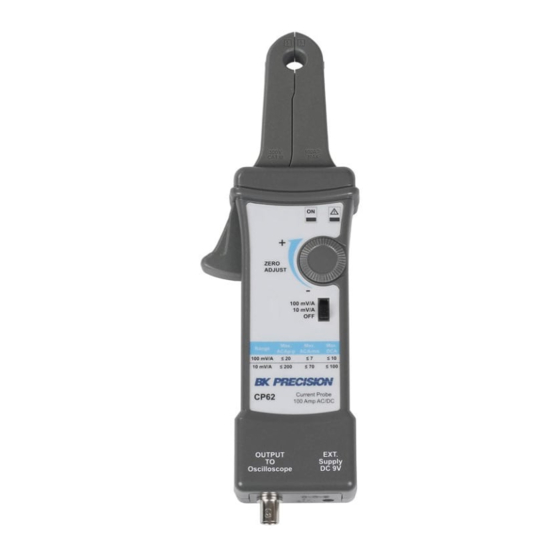
- Page 1 Model: CP62 DC – 100 A Current Probe USER MANUAL 1.800.561.8187 information@itm.com www. .com...
- Page 2 Safety Summary The following safety precautions apply to both operating and maintenance personnel and must be observed during all phases of operation, service, and repair of this instrument. Before applying power, follow the installation instructions and become familiar with the operating instructions for this instrument.
- Page 3 This product uses components which can be damaged by electro-static discharge (ESD). To avoid CAUTION: damage, be sure to follow proper procedures for handling, storing and transporting parts and subassemblies which contain ESD-sensitive components. Compliance Statements Disposal of Old Electrical & Electronic Equipment (Applicable in the European Union and other European countries with separate collection systems) This product is subject to Directive 2002/96/EC of the European...
- Page 4 CE Declaration of Conformity The model CP62 meets the requirements of 2006/95/EC Low Voltage Directive and 2004/108/EC Electromagnetic Compatibility Directive with the following standards. Low Voltage Directive EN61010 Safety requirements for electrical equipment for measurement, control, and laboratory use. EMC Directive EN55011 For radiated and conducted emissions.
-
Page 5: Table Of Contents
INTRODUCTION ..............6 1.1 Introduction ....................6 1.2 Description ....................6 1.3 Specifications ................... 6 Table 1.3.0 Electrical Characteristics ..............6 Table 1.3.1 Voltage and current ratings ............. 6 Table 1.3.2 Physical Characteristics ..............7 ... -
Page 6: Introduction
The CP62 current probe allows a general purpose oscilloscope to display AC and DC current signals up to 100 A Peak (70 A RMS). The CP62 current probe can also make AC and DC measurements with a multimeter by using the recommended accessory TL62 (BNC-to-banana) plug adapter. -
Page 7: Table 1.3.2 Physical Characteristics
Table 1.3.2 Physical Characteristics Dimensions 280 mm x 70mm x 32 mm (11 x 2.8 x 1.3 inch) Maximum Conductor Size 11 mm (0.43 inch) Cable Length 100 cm ( 3.3 feet) Weight 260 g (9.5 oz) (without battery) Table 1.3.3 Environmental Characteristics Temperature Working 0°C to +50°C (+32°F to +122°F) - Page 8 CP62 – Operating Manual Figure 2: Maximum current versus frequency Figure 3: DC signal linearity in the 10 mV/A range, typical 1.800.561.8187 information@itm.com www. .com...
-
Page 9: Table 1.3.5 Certifications And Compliances
Figure 4: Phase versus frequency at 1 A peak, typical Table 1.3.5 Certifications and compliances Compliance was demonstrated to the following specification as listed in the Official Declaration Journal of the European Union: Low Voltage Directive 73/23/EEC, as amended by 93/68/EEC Conformity EN 61010-1/A2:1995 –... - Page 10 CP62 – Operating Manual Certifications and compliances (cont.) Installation Terminals on this product may have different installation (overvoltage) (Overvoltage) category designations. The installation categories are: Category CAT III Distribution-level mains (usually permanently connected). Equipment at this level is typically in a fixed industrial location.
-
Page 11: Installation
Installation 2.1 Introduction This section contains installation information, power requirements, initial inspection, and probe connections for the CP62. 2.2 Package Contents Please inspect the instrument mechanically and electrically upon receiving it. Unpack all items from the shipping carton, and check for any obvious signs of physical damage that may have occurred during transportation. -
Page 12: Operating Instructions
Operating Instructions 3.1 General Description This section describes the controls and connectors of the current probe. Power/ Range Power ON/OFF, select 10mV/A or 100mV/A range Switch DC Zero Offset Knob Max. 11 mm Wire Clamp Clamp Lever Opens jaw Battery Located inside Compartment Output... -
Page 13: Controls And Indicators
3.3 Connectors The CP62 has one BNC connector and one AC input. BNC Output Use this connector to transfer the induced signals to either an oscilloscope or to a digital multimeter. -
Page 14: Oscilloscope Measurements
2. Move the OFF/ Range switch to the 10 mV/A or 100 mV/A position to turn on the probe. (*The CP62 current probe has a green LED power/battery indicator. If the LED does not light, replace the battery or use specified power adapter.) 3. -
Page 15: Multimeter Measurements
To increase the measurement sensitivity of the CP62 current probe, loop additional turns of the wire under test through the jaws. See Figure 7. The sensitivity of the CP62 current probe is multiplied times the number of loops in the jaws. For example: 10 mV/A X 4 turns = 40 mV/A. -
Page 16: Maintenance
It is safe to power the CP62 with the AC adapter while the battery is installed. Disconnecting the external power supply will not produce waveform anomaly or any damage. However, when operating the CP62 with the AC adapter for an extended time period (more than 1 week), removal of the battery is recommended, to avoid battery leakage. -
Page 17: Cleaning
9V Battery Figure 9: 2014 version 4.3 Cleaning: To clean the probe exterior, use a soft cloth dampened in a solution of mild detergent and water. To clean the core, open the jaw and clean the exposed core surfaces with a cotton swab dampened with isopropyl alcohol. - Page 18 CP62 – Operating Manual SERVICE INFORMATION Warranty Service: Please go to the support and service section on our website at to obtain an RMA #. Return the product in the original packaging with proof of purchase to the address below. Clearly state on the RMA the performance problem and return any leads, probes, connectors and accessories that you are using with the device.
- Page 19 © 2014 B&K Precision Corp. v063014 1.800.561.8187 information@itm.com www. .com...
Need help?
Do you have a question about the CP62 and is the answer not in the manual?
Questions and answers