Advertisement
Quick Links
Advertisement

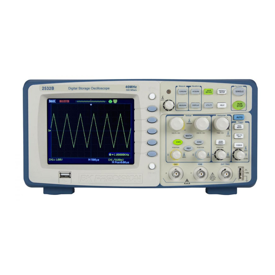
Summary of Contents for BK Precision 2530B
- Page 1 Model: 2530B, 2532B Calibration and Adjustment Procedure V111011...
-
Page 2: Revision History
Revision History Date Edition Revise Reason Revise Content Revised by 11.04.10 V1.0 None None Jason 11.10.11 V111011 Complete re-edit Jeremy... -
Page 3: Calibration Procedure
Calibration Procedure To calibrate the 2530B or 2532B Digital storage oscilloscope, user must first unlock access to calibration menu. How to Unlock Access to Calibration Menu 1. Unplug all attached inputs, power off the instrument, and restart. 2. Press UTILITY button. - Page 4 5. On the screen, the voltage scale should be at 10 V/div, timebase should be 2.50 ms, and you should see a DC signal at 30 V. Change the timebase to 2.50 us. Make sure “Source” in the soft menu is set to “CH1”.
- Page 5 Figure 2 - -30 VDC mean(-) 10. If you adjusted according to the above, you should be able to calculate the mean(+) – mean(-) value to be 60 V (30 – (-30) = 60). 11. Once finished, turn the CH1 volt/div knob to set to 5.00 V scale. Keep timebase at 2.50 us. Repeat steps 6-10, except with 15 V signal from the calibrator, adjust mean(+) to 15.00V and mean (-) to –15.00 V to calculate the difference equal to 30 V.
- Page 6 Trigger Adjustments 1. From the calibrator, setup a Sine signal with frequency of 200 Hz and amplitude of 3 Vpp. Make sure there is 0 offset. 2. Input this signal into CH1 input and press AUTO button for automatic rescaling. 3.
- Page 7 10. Use the trigger LEVEL knob to find out the upper limit and lower limit of the trigger range. To do this, turn the knob to increase the trigger level up until the signal is no longer triggered. This will be the upper limit, so make note of the voltage of this level.
- Page 8 Example: o Upper limit trigger range = 3.12 V and lower limit trigger range = -7.04 V, as illustrated below. When adjusted beyond these two points, signal is no longer triggered and will move across the screen. o (3.12V – (-7.04V) ) / 2 = 5.08 V. This will be the current trigger center level. o Turn the LEVEL knob until trigger level is set to 5.08 V level.
- Page 9 o Turn the LEVEL knob to -5.08 V now and make sure the waveform is still triggered (see image below). If not, re-adjust the “center” value. 17. Now, we will adjust the trigger range. Select CH1 as “Source” in the soft menu. 18.
- Page 10 22. Once finished, repeat and do the same (steps 19-21) for all other vertical scales (i.e. 10V/div, 5V/div,…,2mV/div). You may need to adjust the amplitude of the signal output from the calibrator to scale the waveform to fit on screen. 23.
- Page 11 How to Lock Access to Calibration Menu Once all adjustments are made and self calibration is completed, the instrument must be set back to lock access to the calibration menu. This will bring the instrument back to normal operation mode. Follow the below instructions to do this.


Need help?
Do you have a question about the 2530B and is the answer not in the manual?
Questions and answers