Table of Contents
Advertisement
Quick Links
Advertisement
Table of Contents

Subscribe to Our Youtube Channel
Related Manuals for BK Precision BA8100


Summary of Contents for BK Precision BA8100
- Page 2 Safety Summary The following safety precautions apply to both operating and maintenance personnel and must be followed during all phases of operation, service, and repair of this instrument. Before applying power to this instrument: • Read and understand the safety and operational information in this manual. •...
- Page 3 You must ensure that each accessory you use with this instrument has a category rating equal to or higher than the instrument’s category rating to maintain the instrument’s category rating. Failure to do so will lower the category rating of the measuring system. Electrical Power This instrument is intended to be powered from a CATEGORY II mains power environment.
- Page 4 • In environments with restricted cooling air flow, even if the air temperatures are within specifications. • In direct sunlight. This instrument is intended to be used in an indoor pollution degree 2 environment. The operating temperature range is C to 40 C and 20% to 80% relative humidity, with no condensation allowed.
- Page 5 Hazardous voltages may be present in unexpected locations in circuitry being tested when a fault condition in the circuit exists. Fuse replacement must be done by qualified service-trained maintenance personnel who are aware of the instrument’s fuse requirements and safe replacement procedures. Disconnect the instrument from the power line before replacing fuses. Replace fuses only with new fuses of the fuse types, voltage ratings, and current ratings specified in this manual or on the back of the instrument.
- Page 6 Symbol Description Indicates a hazardous situation which, if not avoided, will result in death or serious injury. Indicates a hazardous situation which, if not avoided, could result in death or serious injury Indicates a hazardous situation which, if not avoided, will result in minor or moderate injury Refer to the text near the symbol.
-
Page 7: Table Of Contents
Contents General Information Features Contents Dimensions Front Panel Overview Display Rear Panel Overview Getting Started Input Power and Fuse Requirements Fuse Requirements Fuse Replacement Theory of Operation Connections Input Sense Measurement Modes Measurement Setup Setting DC Current Level Setting AC Current Level Setting Frequency and Sweep 4.3.1 Single Frequency... - Page 8 System Setup Menu 7.1.1 Input Settings 7.1.2 Display Settings 7.1.3 I/O Configuration 7.1.4 Protection 7.1.5 System Setup Remote Interface USBVCP RS-232 Ethernet Local and Remote Mode Service Information 10 LIMITED THREE-YEAR WARRANTY...
-
Page 9: General Information
Electrochemical Impedance Spectroscopy (EIS) the unit plots the battery’s response at each frequency. The data can be generated as a Nyquist, Bode, or V/I plot. The BA8100 is capable of measuring the parameters listed in chapter individual cells or strings not exceeding 80 V. These functions make the BA8100 ideal for troubleshooting, maintaining, and conducting performance test on batteries. -
Page 10: Contents
General Information 1.2 Contents The following items are included in the box: • BA8100 Battery Analyzer • Kelvin connection test leads • Power Cord • Self-Test Fixture(TLC81) • Certificate of Calibration Note: Ensure the presence of the items. Contact the distributor or B&K Precision if anything is missing. -
Page 11: Front Panel Overview
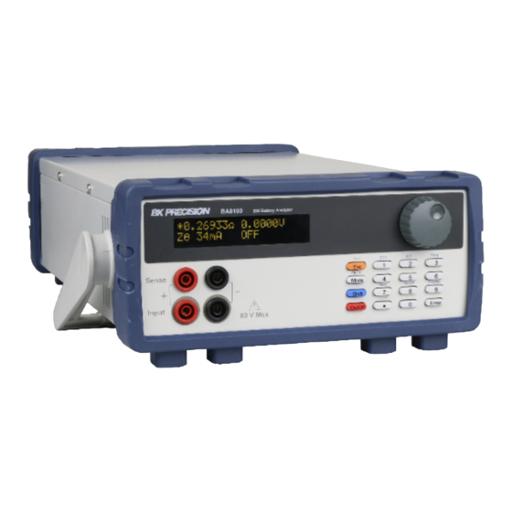
General Information 1.4 Front Panel Overview The front panel interface allows for control of the unit. Figure 1.2 Front Panel Description Item Name Display Visual presentation of the device function and measurements. Input and Sense Connections Connection terminals for the provided Kelvin connection test leads. Control Keys Includes Esc, Mode/Menu, Shift and On/Off keys. -
Page 12: Display
General Information 1.5 Display Figure 1.3 Display Description Item Name Primary Measurement Displays the primary measurement value. See section for more details. Secondary Measurement Displays the secondary measurement value. See section for more details. Measurement Mode Displays the select measurement mode. Primary Measurement Indicator Displays the selected primary mode. -
Page 13: Rear Panel Overview
General Information 1.6 Rear Panel Overview Figure 1.4 Rear Panel Overview Description Item Name Power Switch Powers the unit ON or OFF. AC Power Input Houses the fuse as well as the AC input. & Fuse Box RS232 Connect a straight RS 232 cable to remotely control the unit. Connect an ethernet cable to remotely control the instrument. -
Page 14: Getting Started
Getting Started 2.1 Input Power and Fuse Requirements The supply has a universal AC input that accepts line voltage input within: Voltage: 100 - 240 VAC (+/- 10 %) Frequency: 50/60 Hz Input Power: 60 VA MAX. Before connecting to an AC outlet or external power source, be sure that the power switch is in the OFF position. -
Page 15: Fuse Requirements
Getting Started 2.2 Fuse Requirements An AC input fuse is necessary when powering the instrument. The table below shows the fuse required. Fuse Specification T3AL, 250 V A second fuse can be found within the fuse box. 2.3 Fuse Replacement For safety, no power should be applied to the instrument while changing line voltage operation. -
Page 16: Theory Of Operation
2.4 Theory of Operation The BA8100 stimulates the DUT using a small amplitude and a precisely timed alternating current signal. The unit compares the reference signal and the response signal. By measuring the current and voltage signal at various frequencies, a spectrum of internal impedance is derived. -
Page 17: Measurement Modes
Measurement Modes The BA8100 contains two measurement modes: primary mode and secondary mode. To enter primary and secondary mode press the button then press the button. The letter m can be seen in to top right side of the screen. The m specifies the current mode state. If blinking "M" is displayed the instrument is in secondary mode. If the blinking "m"... -
Page 18: Measurement Setup
Measurement Setup Follow the instructions in to ensure cabling will not have a major impact on the measurements. Note: The sweep function as well as plot functions are only available through the BK-FRA software. Only the measurements listed in Chapter can be obtained through the unit’s display. -
Page 19: Setting Frequency And Sweep
Measurement Setup 4.3 Setting Frequency and Sweep It is standard to test batteries at 1KHz. However, measurements across a range of frequencies provide more information than a single resistance measurement (at steady state or DC loading). To test across a range of frequencies use sweep mode. -
Page 20: Making A Measurement
Measurement Setup Note: As frequency increases, the physical arrangement of the test leads has a greater impact. Reduce the loop area created by the test leads when working at higher frequencies to reduce the inductance of the cabling. 4.4 Making a Measurement Once the appropriate stimulus values have been specified, connect the battery. -
Page 21: Verification Test
The user calibration procedure can be completed to the front panel or to the test leads. The BA8100 uses a single memory location to store the compensation data. This memory will be over written each time the user calibration is completed. -
Page 22: Verification Procedure
If after completing a user calibration to the test leads the verification test to the leads is still failing, the next step is to complete a user calibration to the front panel and conduct the verification procedure to the front panel. If the verification to the front panel also fails the BA8100 will have to be sent in for repair and calibration. Note: The BA8100 along with the TLC81 when must be shipped together when sent in for repair or calibration. -
Page 23: Verification Procedure To The Front Panel
Before initiating the verification to the front panel verify that the last user calibration was completed to the front panel. 1. Set the BA8100 to Zθ mode. 2. Connect the TLC81 to the BA8100. The fixture directly connects to the four inputs located in the front panel. Note: Verify the arrow on the TLC81 is facing up. -
Page 24: Compensating To The Test Leads
4. Connect the power supply to the TLC81’s power input. 5. Set the power supply’s voltage to 5 V and its current to set DCI of the BA8100 (Recomended load: .5 A). 6. Enable the BA8100 input and the power supply’s output. -
Page 25: User Calibration
Verification Test 5.4 User Calibration Configuration of the settings in calibration mode can change the unit’s measurement accuracy. Only adjustments to the ACA Ratio should be made. 5.4.1 User Calibration to the Test Leads To perform a user calibration to the test leads connect the leads front the front panel to the TLC81. Power the TLC81 using a 5 V 3 A source. -
Page 26: User Calibration To The Front Panel
Verification Test 5. Select LOF ACA Ratio. • Set the RUT value to 5.0000 mΩ. • Press to begin the compensation adjustment. – This process can take up to 20 mins to complete. 6. After both ACA Ratio and LOF ACA Ratio have been adjusted select Save Data to save the new ratios. 7. - Page 27 Verification Test 3. Use the rotary knob to navigate through the Calibration Menu. 4. Select ACA Ratio. • Set the RUT value to 5.0000 mΩ. • Press to begin the compensation adjustment. – This process can take up to 5 mins to complete. 5.
-
Page 28: Operating Software
Operating Software 6.1 Software Installation The software can be found in the BK Precision website under the product’s page Docs & Software tab. Download the BK-FRA software and install it. Before you launch the software: 1. Connect the BA8100 and PC using a USB cable. -
Page 29: Control Panel
Operating Software 6.3 Control Panel Figure 6.1 Control Panel The Control Panel is seperated into 6 sections: Frequency/Amplitude Sweep Analysis Sample Output Condition Output State 6.3.1 Frequency/Amplitude Set the parameters of the alternating current signal. • Frequency: Sets the frequency of the AC signal making a single point measurement(sweep is disabled). •... -
Page 30: Sweep
Operating Software 6.3.2 Sweep • Start: Set the starting frequency of the sweep. • Stop: Set the stopping frequency of the sweep. • dB: Set the start and stop frequency for a logarithmic increment sweep. • Lin: Set the start, stop and step frequency for linear increment sweep based on the Step value set. -
Page 31: Analysis
+-180 or +360. • Meter: Opens the Impedance Meter window. – Clicking the MEAS. button will enable measurements. – Displays the measurements that are currently being acquired by the BA8100. See Figure 6.6. • V&C: Opens the Voltage & Current window. - Page 32 Operating Software • Nyquist: Opens the Impedance Nyquist window. – Graphs the real vs the imaginary part of the impedance as functions of freauency. – Enabling Freq. Marker will display the frequency value at which the selected point was measured. Figure 6.7 Impedance Nyquist •...
-
Page 33: Sample
Operating Software 6.3.4 Sample • Sec/Cycle Sets the dwell time of each step. – Enabling Auto will set the dwell time based on the time required for the frequency to acquired data. (Smaller frequencies require more time to acquire data.) 6.3.5 Output Condition •... -
Page 34: Test Results
Operating Software 6.5 Test Results The sweep can be plotted in a Nyquist, Voltage and Current, or Bode plot. These plots must be analyzed to interpret various parameters of the DUT. -
Page 35: Data Logging
Operating Software 6.6 Data Logging Check the LOG box to record the data collected. The box is highlighted blue when checked. The file path can be set once the sweep elapse. The data is saved as a .CSV file. -
Page 36: System Setup
System Setup Press the button then press the button to enter the system menu. Use the rotary knob to navigate between each menu and setting. The button integrated in the knob navigates up one menu level if available. Press the button to enter the selected menu. -
Page 37: I/O Configuration
System Setup 7.1.3 I/O Configuration RS-232 communication speed (4800, 9600, 19200, 38400, 57600, 115200) RS232 Baud Rate Default: 9600 Serial transmission termination character. Carriage return (CR), Line Feed (LF) Term Character or both (CR+LF). Default: CR + LF Ethernet/LAN settings. DHCP is not supported. Network •... -
Page 38: Remote Interface
1. Install the FRA software and NI VISA. – Follow the instructions given in Ch 6. 2. Connect the device interface at the rear panel of BA8100 Series with a PC via a USB,RS232, or LAN. Note: The BA8100 automatically switches to active remote interface when connected to remote interface. - Page 39 EIS Battery Analyzer BA8100 Specifications Note: All specifications apply to the unit after a temperature stabilization time of 30 minutes over an ambient temperature range of 23 °C ± 5 °C. BA8100 Input Voltage 0.5 V to 80 V Power...
-
Page 40: Service Information
Service Information Warranty Service: Please go to the support and service section on our website at bkprecision.com to obtain an RMA #. Return the product in the original packaging with proof of purchase to the address below. Clearly state on the RMA the performance problem and return any leads, probes, connectors and accessories that you are using with the device. -
Page 41: Limited Three-Year Warranty
LIMITED THREE-YEAR WARRANTY B&K Precision Corp. warrants to the original purchaser that its products and the component parts thereof, will be free from defects in workmanship and materials for a period of three years from date of purchase. B&K Precision Corp. will, without charge, repair or replace, at its option, defective product or component parts. Returned product must be accompanied by proof of the purchase date in the form of a sales receipt.
Need help?
Do you have a question about the BA8100 and is the answer not in the manual?
Questions and answers