Table of Contents
Advertisement
Quick Links
Quick Installation Guide
Moxa Americas:
Toll-free: 1-888-669-2872
Tel:
1-714-528-6777
Fax:
1-714-528-6778
Moxa Europe:
Tel:
+49-89-3 70 03 99-0
Fax:
+49-89-3 70 03 99-99
Moxa India:
Tel:
+91-80-4172-9088
Fax:
+91-80-4132-1045
UC-5100 Series
Edition 1.0, May 2018
Technical Support Contact Information
www.moxa.com/support
2018 Moxa Inc. All rights reserved.
Moxa China (Shanghai office):
Toll-free: 800-820-5036
Tel:
+86-21-5258-9955
Fax:
+86-21-5258-5505
Moxa Asia-Pacific:
Tel:
+886-2-8919-1230
Fax:
+886-2-8919-1231
P/N: 1802051001010
*1802051001010*
Advertisement
Table of Contents

Related Manuals for Moxa Technologies UC-5100 Series


Summary of Contents for Moxa Technologies UC-5100 Series
- Page 1 UC-5100 Series Quick Installation Guide Edition 1.0, May 2018 Technical Support Contact Information www.moxa.com/support Moxa Americas: Moxa China (Shanghai office): Toll-free: 1-888-669-2872 Toll-free: 800-820-5036 Tel: 1-714-528-6777 Tel: +86-21-5258-9955 Fax: 1-714-528-6778 Fax: +86-21-5258-5505 Moxa Europe: Moxa Asia-Pacific: Tel: +49-89-3 70 03 99-0...
-
Page 2: Model Names And Package Checklist
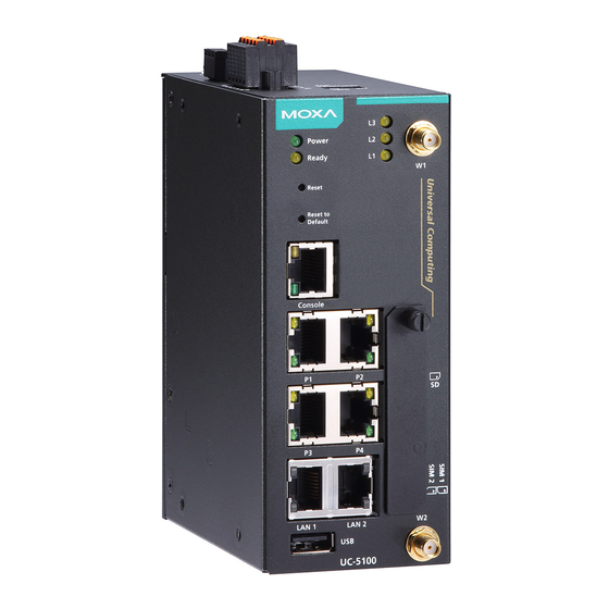
Overview The UC-5100 Series embedded computers are designed for industrial automation applications. The computers feature 4 RS-232/422/485 full- signal serial ports with adjustable pull-up and pull-down resistors, dual CAN ports, dual LANs, 4 digital input channels, 4 digital output channels, a SD socket, and a mini PCIe socket for wireless module in a compact housing with convenient front-end access to all these communication interfaces. - Page 3 NOTE The console cable and power jack can be found beneath the molded pulp cushioning inside the product box. Appearance UC-5101 UC-5102 - 3 -...
-
Page 4: Led Indicators
UC-5111 UC-5112 LED Indicators The function of each LED is described in the table below: LED Name Status Function Green Power is on and the device is Power functioning normally Power is off Yellow OS has been successfully enabled Ready and the device is ready Green Steady On: 10 Mbps Ethernet link... -
Page 5: Reset To Default Button
LED Name Status Function Green Serial port is transmitting data Serial (Tx) Serial port is not transmitting data Yellow Serial port is receiving data Serial (Rx) Serial port is not receiving data Yellow The number of glowing LEDs indicates the signal strength. L1/L2/L3 All LEDs: Excellent (UC-... -
Page 6: Connecting The Power
ATTENTION Safety First! Be sure to disconnect the power cord before installing and/or wiring your UC-5100 Series computers. Wiring Caution! Calculate the maximum possible current in each power wire and common wire. Observe all electrical codes dictating the maximum current allowable for each wire size. If the current goes above the maximum ratings, the wiring could overheat, causing serious damage to your equipment. -
Page 7: Grounding The Unit
NOTE The input rating of UC-5100 Series is 9-48 VDC, 0.95-0.23 A. Grounding the Unit Grounding and wire routing help limit the effects of noise due to electromagnetic interference (EMI). Run the ground connection from the terminal block connector to the grounding surface prior to connecting the power. -
Page 8: Connecting To Di/Do Devices
RS-232 RS-422 RS-485 TxD+ TxD- RxD+ Data+ RxD- Data- Connecting to DI/DO Devices The UC-5100 computer comes with 4 digital inputs and 4 digital outputs. The DI/DO connectors are located on the top panel of the computer. Refer to the adjacent diagram for the pin definitions. - Page 9 Connecting the Cellular/Wi-Fi Module and Antenna The UC-5102 and UC-5112 computers come with one Mini PCIe socket for installing a cellular or Wi-Fi module. Unfasten the two screws on the right panel to remove the cover and find the location of the socket. The cellular module package includes 1 cellular module, and 2 screws.
- Page 10 2. Insert the cellular module into the socket and fasten two screws (included in the package) on to the top of the module. We recommended using a tweezer when installing or removing the module. 3. Connect the free ends of the two antenna cables next to the screws as shown in the image.
-
Page 11: Installing Micro Sim Cards
2. Insert the cellular module into the socket and fasten two screws (included in the package) on to the top of the module. We recommended using a tweezer when installing or removing the module. 3. Connect the free ends of the two antenna cables next to the screws as shown in the image. -
Page 12: Installing The Sd Card
Installing the SD Card The UC-5100 Series computers come with a socket for storage expansion that allows users to install an SD card. Follow these steps to install the SD card: 1. Unfasten the screw and remove the panel cover.
Need help?
Do you have a question about the UC-5100 Series and is the answer not in the manual?
Questions and answers