
Related Manuals for Moxa Technologies UC-8100A-ME-T Series


Summary of Contents for Moxa Technologies UC-8100A-ME-T Series
- Page 1 UC-8100A-ME-T Series Quick Installation Guide Version 3.2, January 2024 Technical Support Contact Information www.moxa.com/support 2024 Moxa Inc. All rights reserved. P/N: 1802081121014 *1802081121014*...
-
Page 2: Package Checklist
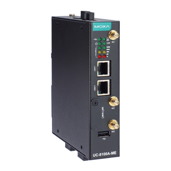
Overview The UC-8100A-ME-T computing platform is designed for embedded data acquisition applications. The UC-8100A-ME-T computer comes with two RS-232/422/485 serial ports and dual 10/100 Mbps Ethernet LAN ports, as well as a Mini PCIe socket to support cellular modules. These versatile communication capabilities let users efficiently adapt the UC- 8100A-ME-T to a variety of complex communications solutions. - Page 3 Bottom Panel View Front Panel View - 3 -...
-
Page 4: Led Indicators
LED Indicators LED Name Color Function Steady On USB device is connected and working normally. Green USB device is not connected. Steady On SD Card inserted and working normally. Green SD card is not detected. Power is on and the computer is Green working normally. -
Page 5: Connector Description
1. Pull down the bottom slider of the DIN-rail bracket located at the back of the unit 2. Insert the top of the DIN rail into the slot just below the upper hook of the DIN-rail bracket. 3. Latch the unit firmly onto the DIN rail as shown in the illustrations below. - Page 6 WARNING EXPLOSION HAZARD! Do not disconnect equipment unless the power has been removed or the area is known to be non-hazardous. Grounding the UC-8100A-ME-T Grounding and wire routing help limit the effects of noise due to electromagnetic interference (EMI). SG: The Shielded Ground (sometimes called Protected Ground) contact is the top contact of the 3-pin power terminal block connector when viewed from the angle shown here.
-
Page 7: Real-Time Clock
socket, and then insert the SD card or the SIM card into the sockets directly. You will hear a click when the cards are in place. To remove the cards, push the cards in before releasing them. Console Port The console port is an RS-232 port that can be connected to a 4-pin pin header cable. -
Page 8: Specifications
ATTENTION There is a risk of explosion if the battery is replaced with an incorrect type of battery. Accessing the UC-8100A-ME-T Using a PC You can use a PC to access the UC-8100A-ME-T by one of the following methods: A. Through the serial console port with the following settings: Baudrate= 115200 bps, Parity= None, Data bits= 8, Stop bits= 1, Flow Control= None ATTENTION... - Page 9 Hazardous Location Specifications Model UC-8112A-ME-T-LX ATEX Information Certificate Number: DEMKO 19 ATEX 2295X Certification String: Ex nA IIC T4 Gc Ambient Range: -40°C ≦ Tamb ≦ 85°C (without LTE module preinstalled) Ambient Range: -40°C ≦ Tamb ≦ 70°C (with LTE module preinstalled) Rated Cable Temp ≧...
Need help?
Do you have a question about the UC-8100A-ME-T Series and is the answer not in the manual?
Questions and answers