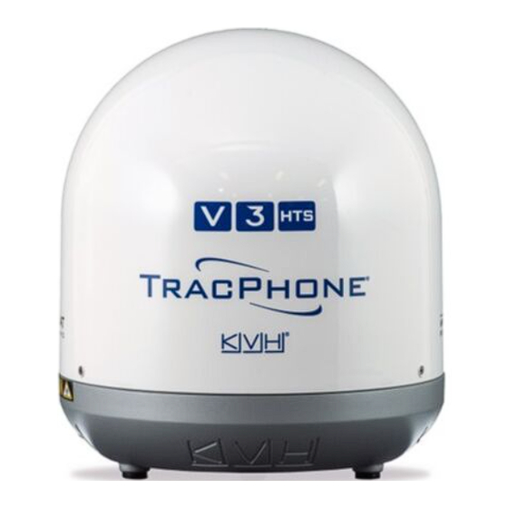
KVH Industries TracPhone V3-HTS Installation Manual
Mini-vsat broadband system with integrated commbox modem
Hide thumbs
Also See for TracPhone V3-HTS:
- Quick start manual (2 pages) ,
- Replacement instructions manual (10 pages) ,
- Replacement instructions (4 pages)
Table of Contents
Advertisement
Advertisement
Table of Contents

Subscribe to Our Youtube Channel
Related Manuals for KVH Industries TracPhone V3-HTS


Summary of Contents for KVH Industries TracPhone V3-HTS
- Page 1 TracPhone ® Installation Guide...
-
Page 2: Table Of Contents
KVH, TracPhone, CommBox, IP-MobileCast, and the unique light-colored dome with dark contrasting baseplate are trademarks, and mini-VSAT Broadband is a service mark, of KVH Industries, Inc. All other trademarks are property of their respective companies. The information in this document is subject to change without notice. No company shall be liable for errors contained herein. - Page 3 Important Safety Information This icon indicates a danger, warning, or caution notice. Be sure to read these carefully to avoid injury. WARNING Risk of Electric Shock Potentially lethal voltages are present within the ICM when it is connected to AC power. To avoid electric shock, do not open the chassis enclosure.
-
Page 4: Inspect Parts And Get Tools
• Isolation transformer, if required (see page 18) • Light hammer and center punch • RS422-to-USB adapter • Adhesive tape • Laptop PC with the latest TracPhone V3-HTS • Silicone sealant, self-vulcanizing tape, or ICM/antenna software (.kvh) downloaded from equivalent the KVH Partner Portal (www.kvh.com/... -
Page 5: Plan The Antenna Installation
Plan the Antenna Installation Before you begin, consider the following antenna installation guidelines. Figure 2: Antenna Dimensions Side View Choose a Suitable Location • Select a location that is as close as possible to the intersection of the vessel’s centerline and midships. - Page 6 Continued Plan the Antenna Installation Meet Pedestal Structure Requirements If a pedestal is going to be used, it must meet the following minimum requirements. Refer to Figure 3. Figure 3: Pedestal and Brace Dimensions Pedestal Brace 120° Pedestal Height (A) 3.28 ft (1 m) 6.56 ft (2 m) 9.84 ft (3 m)
- Page 7 Continued Plan the Antenna Installation Prevent RF Radiation Exposure Figure 4: Blockage from Obstruction Select a location that is well above any areas accessible to passengers and crew to reduce the Blocked! risk of RF radiation exposure. (See page 1 for an illustration of the hazard area.) 7.7°...
-
Page 8: Plan The Icm Installation
Plan the ICM Installation Before you begin, consider the following Figure 6: ICM Dimensions installation guidelines for the ICM. • Select a mounting location in a dry, well- Strain-Relief Bracket 16.31" ventilated area belowdecks away from any (41.43 cm) heat sources or salt spray. •... -
Page 9: Mount The Icm
Mount the ICM There are two options for mounting the ICM: Figure 7: Attaching the Strain-Relief Bracket Option 1 - Inside an equipment rack Option 2 - To a horizontal surface NOTE: You may choose to wait to mount the ICM until after you have completed all system wiring. -
Page 10: Prepare The Antenna Site
Prepare the Antenna Site Once you have identified a suitable antenna Figure 11: Antenna Mounting Holes Layout mounting site, according to the guidelines provided in “Plan the Antenna Installation” on page 4, follow these steps to prepare the site for Ø3.5"... -
Page 11: Remove The Shipping Restraints
Remove the Shipping Restraints Inside the antenna, two shipping restraints Figure 12: Removing the Radome prevent the antenna assembly from moving during shipment. Follow these steps to remove these restraints. a. Remove the three #10-32 Phillips screws securing the radome to the baseplate (see Figure 12). -
Page 12: Prepare The Antenna Cables
Prepare the Antenna Cables Follow these steps to prepare and route the RF Figure 14: RF Cable Options and power/data cables. RG-11 Prepare the Customer’s RF Cables Max. length 100 ft (30 m) You need to connect two 75 RF coax cables KVH part no. - Page 13 Continued Prepare the Antenna Cables Connect the Customer’s RF Cables to the Figure 15: Connecting the Pigtail Cables to the RF Cables Supplied Pigtail Cables To Antenna Right-Angle Connectors IMPORTANT! (type “F”) Use of the supplied RG-11 pigtail cables is mandatory if you are using LMR cables.
-
Page 14: Wire The Antenna
Wire the Antenna Follow these steps to connect the antenna cables. Figure 18: Antenna Cable Connections a. Connect the power/data cable to the “Power/Data” jack on the bottom of the antenna (see Figure 18). Hand-tighten until the connector locks in place. b. -
Page 15: Mount The Antenna
Mount the Antenna Follow these steps to mount the antenna. Figure 20: Forward Arrow in Antenna Baseplate a. Place the antenna over the holes drilled in the mounting surface and make sure the forward arrow inside the baseplate points toward the bow and is parallel to the vessel’s centerline (see Figure 20). -
Page 16: Wire The Icm
Wire the ICM Follow these steps to wire the belowdecks Figure 22: Jumper Cable and Wi-Fi Antenna Connection equipment (see page 49 for a complete wiring Wi-Fi Antenna (x2) diagram). Connect the ICM Jumper Cables Connect the supplied straight-through Ethernet jumper cable from the “B1”... - Page 17 Continued Wire the ICM Connect an NMEA 0183 Talker Figure 25: Compatible NMEA 0183 Inputs The antenna requires a vessel heading input from a customer-supplied NMEA talker. Data Type Compatible Messages Optionally, you can also provide a vessel True or Magnetic $--HDG position input to serve as a backup to the Heading...
- Page 18 Continued Wire the ICM Connect the RF Cables Figure 27: Antenna RF Transmit and Receive Wiring IMPORTANT! If you are using LMR-600-75 RF cables, do not TxRF RxRF connect them directly to the ICM. Connect the supplied 1 ft (30 cm) pigtail cables between the RF cables and the ICM.
-
Page 19: Connect Power
Connect Power Before you begin, be sure that you understand Figure 29: AC Power Options the following important requirements: TracPhone Equipment AC Power Requirements The TracPhone system is designed to run on 3-wire single-phase AC power (hot, neutral, and Ground Shipboard ground). - Page 20 Continued Connect Power Once you have read and understand the Figure 30: Power Wiring requirements described on page 18, follow these steps to connect power to the TracPhone system. a. Before you begin, disconnect vessel power and be sure the vessel is properly grounded in Input accordance with marine standards.
-
Page 21: Turn On The System
User Ethernet the following address: http://minivsat.kvh. 1 2 3 4 Verify that the TracPhone V3-HTS web interface appears in your browser. If the web interface is not displayed, enter the ICM’s IP address (you can find this address on the LCD: go to Settings >... -
Page 22: Update The System Software
Follow these steps to ensure the latest software is installed in the TracPhone system. Figure 35: Updates Page on Web Interface Check the Current Software Version a. Go to the TracPhone V3-HTS web interface and click the Updates tab. Note the displayed ICM/Antenna software version (see Figure 35). -
Page 23: Customize The Web Interface
Follow these steps to change the administrator password to something unique. a. At the TracPhone V3-HTS web interface, click the Settings tab. Then click Account. b. In Security, click Edit. c. For the current password, enter the default password: “password”... -
Page 24: Set Up No-Transmit Zones
Figure 41: Azimuths Relative to Antenna’s Forward Arrow Therefore, be sure to set the beginning and ending azimuths at least 5º apart. Beginning Azimuth b. At the TracPhone V3-HTS web interface, click the Settings tab. Then click No-Transmit No-Transmit Zone (Example) Zones. -
Page 25: Set Up Tracking Avoidance Zones
Determine the necessary elevation range for each zone. NOTE: Each no-transmit zone must span at least 5° in both azimuth and elevation. c. At the TracPhone V3-HTS web interface, click the Settings tab. Then click Tracking Avoidance Zones. d. Click Edit. -
Page 26: Commission The Modem
Ensure the antenna has a clear, unobstructed Power Input (dBm) view of the sky. b. At the TracPhone V3-HTS web interface, Figure 45: Good Service Connection Indicated on Home Page verify that the antenna is tracking the service satellite and the system is online (see Figure 45). - Page 27 Continued Commission the Modem e. At Step 1, click Enter Commissioning Mode Figure 47: Commissioning Process – Step 1 (see Figure 47). f. At Step 2, click Continue without changes (see Figure 48). IMPORTANT! If you need to abort commissioning at any time, select Exit commissioning mode.
- Page 28 Continued Commission the Modem k. At Step 4, enter the satellite parameters Figure 50: Commissioning Process – Step 4 provided by the NOC (see Figure 50). Verify that the Frequency and the FL Carrier Symbol Rate match the values on the worksheet, and enter zeros for Latitude Variance and Polarization Skew.
- Page 29 Continued Commission the Modem m. When Start Antenna Pointing appears, click Figure 52: Commissioning – Steps 5 Through 7 Continue (see Figure 52). n. At Step 6, click Continue (see Figure 52). o. At Step 7, click Skip (see Figure 52).
- Page 30 Continued Commission the Modem p. At Step 8, select CW modulation and enter Figure 53: Commissioning – Step 8: CW Modulation the RF Uplink Frequency and the initial Transmit power that the NOC provided (see Figure 53). Then click Turn on signal. q.
- Page 31 Continued Commission the Modem s. Continue by using Adjust L-Band Transmit Figure 56: Commissioning – Step 8: BPSK Modulation continued Power to adjust the power in 1 dB increments as directed by the NOC and selecting Apply changes after each increment (see Figure 56). When directed, click Turn off signal and complete.
-
Page 32: Test The System
Verify that the antenna is tracking the service satellite and the system is online, as indicated by the Home page of the TracPhone V3-HTS web interface (see Figure 59). Figure 60: Heading Displayed on Home Page c. -
Page 33: Configure The Network
Manager, the customer will need to log in with the username and password provided by KVH at the time of activation. a. At the TracPhone V3-HTS web interface, click the Settings tab. Then click Network Settings. b. In Network Configuration, click Edit. - Page 34 NOTE: By default, the High-speed LAN has a gateway of 192.168.5.1 and assigns IP addresses in the 192.168.6.50-150 range. If this configuration conflicts with an existing onboard network, you may Mobile change the settings at the TracPhone V3-HTS web Bridge Ops PC Officers PC Crew PC Devices...
- Page 35 Continued Configure the Network Static IP Configuration Figure 67: Static IP Configuration In a static IP configuration, Ethernet ports 1 through 3 and the built-in WAP provide high- speed Internet access with no user logins or controls. Internet access is unrestricted. Port 4 is reserved for an optional KVH service, such as Global Static IP.
- Page 36 Continued Configure the Network Access Control Configuration Figure 69: Access Control Configuration In an Access Control configuration, Ethernet ports 1 through 3 and the built-in WAP require a user login and provide high-speed Internet access. Port 4 is reserved for an optional KVH service, such as Global Static IP.
- Page 37 NOTE: The customer may also change the ICM’s wireless settings at any time at the mini-VSAT Manager (www.mykvh.com). Figure 73: Wi-Fi Settings on the ICM a. At the TracPhone V3-HTS web interface, click the Settings tab. Then click Network Settings. b. In Wi-Fi Settings, click Edit.
-
Page 38: Connect Voice Line Equipment
Connect Voice Line Equipment Follow these steps to connect the vessel’s phone. Figure 74: Connecting the Vessel Phone (Example) Connect the Vessel Phone Using the supplied RJ-11 cable, connect the Voice Line 1 customer’s analog (not digital) phone or PABX to the “Voice Line 1”... -
Page 39: Educate The Customer
Educate the Customer Give the Welcome Kit to the customer, make sure Figure 75: Customer Welcome Kit they know the administrator and Wi-Fi passwords, and show them how to use the system. Be sure they understand the following: • The antenna transmits RF energy that is potentially harmful. - Page 40 Terminating LMR RF Cables Appendix These instructions explain how to terminate an LMR-400-75 RF cable with an EZ-400-FMH-75 “F” connector using the tools from the Figure 78: Cutting the Cable TK-400EZ-75 tool kit. The same steps also apply to an LMR-600-75 cable, with the exception of the tools used.
- Page 41 Continued Terminating LMR RF Cables Appendix 5. Using a utility knife, carefully remove any residual plastic from the center conductor, if Figure 82: Removing Plastic Residue necessary (see Figure 82). 6. Insert the end of the cable into the #2 end of the ST-400EZ stripping tool (see Figure 83).
- Page 42 Continued Terminating LMR RF Cables Appendix 8. Gently flare the braid with your fingers (see Figure 86). Figure 86: Flaring the Braid 9. Insert the end of the cable into the connector body until the dielectric is firmly seated inside the connector (see Figure 87). Make sure there is no gap between the knurled end of the connector and the cable jacket.
- Page 43 Continued Terminating LMR RF Cables Appendix 12. Using an appropriate crimp tool (either the CT-400/300 or the HX-4 with Y1719 dies), Figure 90: Crimping the Ferrule onto the Cable crimp the ferrule in place (see Figure 90). Crimp as close to the connector body as possible.
- Page 44 Configuring Computers for DHCP Appendix Follow these steps to configure your computer for DHCP to allow it to receive an IP address from the ICM. The location of this configuration Figure 93: Windows 10 - Internet Protocol Properties setting varies slightly by operating system. NOTE: The computer must have a network interface card installed and all cabling must be 100 Mbps fast Ethernet UTP CAT-5 with RJ45 connectors.
- Page 45 Continued Configuring Computers for DHCP Appendix Windows 8 1. Turn on the computer. Figure 94: Windows 8 - Internet Protocol Properties 2. In Control Panel, double-click Network and Sharing Center. To open the Control Panel, go to the desktop, select Settings from the Charms bar, then select Control Panel.
- Page 46 Continued Configuring Computers for DHCP Appendix Windows 7 or Windows Vista 1. Turn on the computer. Figure 95: Windows 7/Windows Vista- Internet Protocol Properties 2. In Control Panel, double-click Network and Sharing Center. (You might need to click Network and Internet first.) You can find the control panel either through the Start menu or “My Computer.”...
- Page 47 Continued Configuring Computers for DHCP Appendix Windows XP 1. Turn on the computer. Figure 96: Windows XP - Internet Protocol (TCP/IP) Properties 2. In Control Panel, double-click Network Connections. You can find the control panel either through the Start menu or “My Computer.”...
- Page 48 Continued Configuring Computers for DHCP Appendix Macintosh OS X 1. Turn on the computer. Figure 97: Macintosh OS X - Network Preferences 2. In System Preferences, click Network. 3. In the Network dialog box, select Ethernet then set the following: •...
- Page 49 Verifying the NMEA 0183 Message Appendix Appendix Verify the message supplied by the NMEA 0183 talker by connecting its output to a laptop using an RS422-to-USB adapter cable and viewing its Figure 98: Connecting a NMEA 0183 Talker to a Laptop data stream using PuTTY, HyperTerminal, or NMEA 0183 Talker other terminal emulator.
- Page 50 Wiring Diagram Appendix Antenna Power/Data Blue/White White/Blue Brown/White White/Brown NMEA 0183 Talker Orange/White (customer-supplied) White/Orange Gray/White White/Gray Ship’s Heading Black Terminal 13 14 15 16 Strip Connector NMEA To Antenna Six unused wires are reserved for future use; N/C = Not Connected Vessel Phone Vessel PC Voice...
- Page 51 Regulatory Compliance European Union Compliance Hereby, KVH Industries, Inc. declares that the radio equipment type TracPhone V3-HTS is in compliance with Directive 2014/53/EU. For the full text of the EU Declaration of Conformity, go to www.kvh.com/euconformity. Federal Communications Commission Compliance The TracPhone system complies with Class B of Part 15 of the FCC (Federal Communications Commission) rules for radiated and conducted emissions.
- Page 52 KVH Industries A/S KVH Industries, Inc. KVH Industries Pte Ltd. EMEA Headquarters World Headquarters Asia-Pacific Headquarters Kokkedal, Denmark Middletown, RI U.S.A. Singapore Tel: +45 45 160 180 Fax: +45 45 160 181 Tel: +1 401 847 3327 Fax: +1 401 849 0045 Tel: +65 6513 0290 Fax: +65 6472 3469 Email: info@emea.kvh.com...
Need help?
Do you have a question about the TracPhone V3-HTS and is the answer not in the manual?
Questions and answers