Table of Contents
Advertisement
Advertisement
Table of Contents

Related Manuals for LumaSense IMPAC IS 310


Summary of Contents for LumaSense IMPAC IS 310
- Page 1 IMPAC Pyrometer IS 310 • IGA 310...
- Page 2 LumaSense Technologies prohibits the duplication of any portion of this manual or the use thereof for any purpose other than the operation or maintenance of the equipment described in this manual, without the express written permission of LumaSense Technologies.
-
Page 3: Table Of Contents
1.3 Limit of liability and warranty ................6 1.4 Unpacking the Instrument ..................6 1.5 Service Request, Repair, or Support ............... 6 1.6 Shipments to LumaSense for Repair ..............7 1.7 Transport, Packing, Storage ..................7 1.8 Disposal / decommissioning ..................7 Introduction ........................ - Page 4 Index ............................23 Contents • iv IS 310 / IGA 310 Manual...
-
Page 5: General Information
1 General Information 1.1 Information about the user manual Congratulations on choosing the high quality and highly efficient IMPAC pyrometer. This manual provides important information about the instrument and can be used as a work of reference for installing, operating, and maintaining your pyrometer. It is important that you carefully read the information contained in this manual and follow all safety procedures before you install or operate the instrument. -
Page 6: Limit Of Liability And Warranty
LumaSense Technologies is not liable for any damages that arise from the use of any examples or processes mentioned in this manual or in case the content of this document should be incomplete or incorrect. -
Page 7: Shipments To Lumasense For Repair
Email eusupport@lumasenseinc.com 1.6 Shipments to LumaSense for Repair All RMA shipments of LumaSense Technologies instruments are to be prepaid and insured by way of United Parcel Service (UPS) or preferred choice. For overseas customers, ship units air- freight, priority one. - Page 8 To ensure consistent document formatting, this page was intentionally left blank. General Information • 8 IS 310 / IGA 310 Manual...
-
Page 9: Introduction
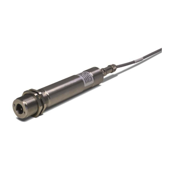
2 Introduction 2.1 Appropriate use The IS 310 and IGA 310 are stationary pyrometers for non-contact temperature measurement of metallic surfaces, graphite, ceramics, etc. 2.2 Scope of delivery Instrument, works certificate, and user manual. Note: A connection cable is not included with the instrument and has to be ordered separately (see Chapter 7, Reference numbers). -
Page 10: Dimensions
Note: The calibration / adjustment of the instruments was carried out in accordance with VDI/VDE directive “Temperature measurement in industry, Radiation thermometry, Calibration of radiation thermometers”, VDI/VDE 3511, Part 4.4. For additional details on this directive, see http://info.lumasenseinc.com/calibration or order the directive from “Beuth Verlag GmbH” in D-10772 Berlin, Germany. 2.4 Dimensions All dimensions in mm *) D: Aperture dependent on instrument type, see Section 3.3 Optics... -
Page 11: Controls And Installation
Controls and Installation 3.1 Electrical Installation The instruments are supplied by 24 V DC (± 25%) and a ripple < 50 mV. Ensure correct polarity when connecting the instrument to the power supply. The power consumption (in this case, 4 ... 20 mA) is also the measuring signal. The instrument doesn’t need any time for starting or preheating and is immediately ready for operation. -
Page 12: Calculation Of The Measuring Temperature From Current Output
Example for wiring using an external power supply: Note: Additional analyzing instruments, e.g. controllers, recorders, etc. can be connected in series as shown in drawing above. 3.1.3 Calculation of the measuring temperature from current output IS 310 MB 18 Temp. [°C] = 71.875 ... - Page 13 The following drawing and table shows the size of the spots in mm in relation to the measuring distance. Values between the mentioned data can be calculated by interpolation. The spot size for measuring distance 0 is the aperture diameter of the optics. Measuring distance Spot size Type...
- Page 14 To ensure consistent document formatting, this page was intentionally left blank. Controls and Installation • 14 IS 310 / IGA 310 Manual...
-
Page 15: Parameter Descriptions / Settings
4 Parameter Descriptions / Settings 4.1 Emissivity (ε) For a correct measurement, it is necessary to adjust the emissivity ε. This emissivity is the relationship between the emission of a real object and the emission of a black body radiation source (this is an object which absorbs all incoming rays and has an emissivity of 100%) at the same temperature. - Page 16 To ensure consistent document formatting, this page was intentionally left blank. Parameter descriptions / settings • 16 IS 310 / IGA 310 Manual...
-
Page 17: Maintenance
5 Maintenance 5.1 Safety If the pyrometer is integrated into a running machine process, the machine has to be switched off and secured against restart before servicing the pyrometer. 5.2 Service The pyrometer has no serviceable internal parts. The lens can be cleaned with compressed air, which is dry and free of oil. - Page 18 To ensure consistent document formatting, this page was intentionally left blank. Maintenance • 18 IS 310 / IGA 310 Manual...
-
Page 19: Troubleshooting
6 Troubleshooting Before sending the pyrometer for repair, try to find the error and to solve the problem with the help of the following list. Temperature indication too low • Incorrect alignment of the pyrometer to the object ⇒ New correct alignment to achieve the max. temperature signal •... - Page 20 To ensure consistent document formatting, this page was intentionally left blank. Troubleshooting • 20 IS 310 / IGA 310 Manual...
-
Page 21: Reference Numbers
7 Reference Numbers 7.1 Reference numbers instrument Temperature Range Pyrometer Optics 650 … 1800 °C 800 … 2300 °C 1100 … 2500 °C (MB 18) (MB 23) (MB 25) a = 250 mm 3 902 210 3 902 250 3 902 310 IS 310 a = 600 mm 3 902 220... - Page 22 Flange system: Ceramic tube ∅ 24, 600 mm long, closed 3 846 240 Tube support with air purge and flange 3 846 280 3 846 250 Support for instrument Reference Numbers • 22 IS 310 / IGA 310 Manual...
- Page 23 Index Accessories 21 Instrument 21 Reference Numbers 21 Accessories 10 Repair 6, 7 Analyzing devices 11 Appropriate use 9 Safety 5 Scope of delivery 9 Calculation of the measuring temperature Service Request 6 Settings / parameter descriptions 15 Changing of optics or fiber 17 Shield 11 Controls and Installation 11 Support 6...
Need help?
Do you have a question about the IMPAC IS 310 and is the answer not in the manual?
Questions and answers